Table of Contents

Related Manuals for Pyronix Castle EURO 162


Summary of Contents for Pyronix Castle EURO 162
- Page 1 EURO 162/280 Installation Manual EN50131-3:2009 EN50131-1:2006+A1:2009 PD6662:2010 Security Grade 3 Environmental Class II Software Version >9.1 Installation Reference For the EURO 162 and EURO 280 control panels RINS1529-3 Page: 1...
-
Page 2: Table Of Contents
EURO 162/280 Installation Manual C o n t e n t s P a g e Contents Page ............................2 1. System Overview ............................ 3 1.1 System Overview..........................3 1.2 The Devices ............................4 1.3 EURO Input Mapping Overview: ......................7 1.4 Output Mapping Overview ........................ -
Page 3: System Overview
EURO 162/280 Installation Manual 1 . S y s t e m O v e r v i e w The EURO control panel is wired control panel that can have a maximum of 162 inputs (EURO 162) or a maximum of 280 inputs (EURO 280). -
Page 4: The Devices
EURO 162/280 Installation Manual 1.2 The Devices 1.2.1 The EURO 162 Bus Diagram All EURO peripherals; LCD keypads, readers, expanders etc. are connected via the D1-, D2+, D3 and D4 terminals. This is an example of what a typical EURO 162 bus may look like. - Page 5 EURO 162/280 Installation Manual 1.2.2 The EURO 280 Bus Diagram All EURO peripherals; LCD keypads, readers, expanders etc. are connected via the D1-, D2+, D3 and D4 terminals. This is an example of what a typical EURO 280 bus may look like. General Principles: NOTE 1: No alarm system cable should be run with other cables...
- Page 6 EURO 162/280 Installation Manual 1.2.3 RS-485 Wiring Wiring Format Bus range Cable type Screened Cable Daisy Chain Range Star Range 4 core alarm cable 300m Use when bus located near No limit. 6 core alarm cable 230VAC mains doubling D1 (0V) 1000m power line and D2 (12V)
-
Page 7: Euro Input Mapping Overview
EURO 162/280 Installation Manual 1.3 EURO Input Mapping Overview: 1.3.1 EURO 162 Input Mapping Table: DEVICES Address Input Numbers EURO 162 PCB 9-16 17-24 25-32 33-40 41-48 EURO-ZEM8 / EURO-ZEM8+ / EURO-ZEM8+PSU / EURO-ZEM32-WE 49-56 57-64 65-72 73-80 81-88 89-96 97-104 105-112 113-120... - Page 8 EURO 162/280 Installation Manual 1.3.2 EURO 280 Input Mapping Table: DEVICES Address Input Numbers EURO 280 PCB 9-16 17-24 25-32 33-40 41-48 EURO-ZEM8 / EURO-ZEM8+/ EURO-ZEM8+PSU / EURO-ZEM32-WE 49-56 57-64 65-72 73-80 81-88 89-96 97-104 105-112 113-120 121-128 129-136 137-144 145-152 153-160 161-168...
-
Page 9: Output Mapping Overview
EURO 162/280 Installation Manual 1.4 Output Mapping Overview 1.4.1 EURO 162 Output Mapping Table DEVICES Address Output Numbers EURO 162i PCB ATE Outputs (using communication ribbon) Ribbon 1-16 17-32 33-48 49-64 EURO-OEM8R8T / EURO-OEM16R+PSU 65-80 81-96 97-112 113-128 EURO-ZEM8+/ EURO-ZEM8+PSU EURO-LCD EURO-LCD / EURO PROXI / EURO PROXE Total... - Page 10 EURO 162/280 Installation Manual 177-192 193-208 209-224 225-240 241-256 EURO-ZEM8+/ EURO-ZEM8+PSU EURO-LCD EURO-LCD / EURO PROXI / EURO PROXE Total Page: 10...
-
Page 11: Installation
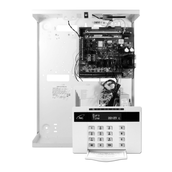
EURO 162/280 Installation Manual 2 . I n s t a l l a t i o n 1. Unscrew and remove the cover of the EURO control panel (Figure 1). 2. Install the supplied stand offs if needed before you mount the metal case to the wall (Figure 3). Figure 1. -
Page 12: The Printed Circuit Board
EURO 162/280 Installation Manual 3 . T h e P r i n t e d C i r c u i t B o a r d 1] Outputs 1 & 2 Relay outputs. See page: 23. 2] Speaker connection Connects a 16ohm speaker. -
Page 13: Technical Specification
EURO 162/280 Installation Manual 3.1 Technical Specification Programmable Outputs Ratings Normal State Active State Output 1 Relay, 3A, max 30V Normally Closed Normally Open Output 2 Relay, 3A, max 30V Normally Closed Normally Open Speaker 16 ohms No tones Repeat RKP tones & internal sounder Strobe Output 500mA Bell Output... -
Page 14: Important Installation Notes
EURO 162/280 Installation Manual EURO PCB Current Consumption Environmental Quiescent 75-90mA Operational -10°C to +40°C, Certified User Code and Tag Guessing Storage -20°C to +60°C 4-digit codes 10,000 Humidity 6-digit codes 100,000 Dimensions Disallowed codes None Metal Casing 390 x 305 x 100mm All codes Weight: 6kg According to EN50131-3:2009 Annex B... -
Page 15: Communication Ate Loom
EURO 162/280 Installation Manual 3.3 Communication ATE Loom The ATE low power outputs are programmed in the engineer function: ‘CHANGE OUTPUTS->Endstation PGMs”. Purple (ATE Output 8: Mains Fail (0052)) Light Grey (ATE Output 10: Test ATS (0064)) White (ATE Output 9: Global Fault 2 (0056)) Black (ATE Output 7: Confirmed Any (0006)) Brown (ATE Output 4: Final Set All (0004)) Red (0V) -
Page 16: Ac Mains Supply Connection
EURO 162/280 Installation Manual 3.5 AC Mains Supply Connection Panel Power Supply Input Nominal Range Mains Supply Voltage AC 230V AC at 50Hz -15% +10% Transformer Rating 45VA 18.5V at 2.5A Panel Power Supply Output Nominal Range Output Voltage 13.7V DC 10-15V DC Output Current 2.0A Continuous... -
Page 17: Engineer Keypad Connection
EURO 162/280 Installation Manual 3.6 Engineer Keypad Connection If required, any keypad can be connected to the 'Engineer Keypad' connections as shown below. This enables quick access to the Engineer menu without having to walk to the nearest keypad. NOTE: Before an Engineer keypad is enabled, it should be addressed as an additional keypad on the EURO control panel before operation. -
Page 18: Default Grade 2 Deol (Double End Of Line) Input Wiring
EURO 162/280 Installation Manual 4.1 Default Grade 2 DEOL (Double End of Line) Input Wiring The above wiring example shows the connections for a Grade 2 KX15DQ PIR detector. 4.2 Grade 3 Mask/Fault Input Wiring The above wiring example shows the connections for a Grade 3 KX15DTAM detector. Page: 18... -
Page 19: Id Wiring
EURO 162/280 Installation Manual 5 . i D W i r i n g The EURO control panels incorporate the feature of iD plus wiring. This gives you a means of simplifying wiring by individually addressing a number of detectors wired to the control panel in parallel. -
Page 20: Connecting Id Biscuits To Pirs (Grade 2)
EURO 162/280 Installation Manual 5.2 Connecting iD Biscuits to PIRs (Grade 2) 5.1 Connecting iD Biscuits to PIRs (Grade 3) Page: 20... -
Page 21: Id Termination
EURO 162/280 Installation Manual For separate fault and mask relays use the below configuration Please note that when using masking you must program the masking biscuit (iD 2 in the above example as ‘fault’) and then pair the corresponding inputs using the ‘paired input’ attribute. It is possible to spur off at this point to a further detector(s). -
Page 22: Id Commissioning Readings
EURO 162/280 Installation Manual 5.3 iD Commissioning Readings On completion of the installation, it is essential that the commissioning readings described below be taken, both to ensure the integrity of the system and to satisfy the documentation requirements of PD6662, etc. This procedure has been agreed with NSI as an acceptable method of meeting these requirements: Complete the wiring, but do not secure the detector housings. -
Page 23: Output (Pgm) Connections
EURO 162/280 Installation Manual 6 . O u t p u t ( P G M ) C o n n e c t i o n s 6.1 Negative Applied Wiring Normal State: NC Active State: 0V Relay Rated at 2A 6.2 Positive Applied Wiring Normal State: NC Active State: +12V... -
Page 24: External Sounder Connections
7 . E x t e r n a l S o u n d e r C o n n e c t i o n s 7.1 Grade 3 External Sounder Wiring Pyronix Grade 3 External Sounders: Deltabell Plus... -
Page 25: Grade 2 External Sounder Wiring
EURO 162/280 Installation Manual 7.3 Grade 2 External Sounder Wiring Pyronix Grade 2 External Sounders: Deltabell E Invincibell E Page: 25... -
Page 26: Connecting The Euro Peripherals
EURO 162/280 Installation Manual 8 . C o n n e c t i n g t h e E U R O P e r i p h e r a l s 8.1 Connecting The LCD Keypad (EURO-LCD) The EURO-LCD keypad is used for programming and user operation. - Page 27 EURO 162/280 Installation Manual The default address is '00'. Enter the required Address and press Press a to exit. You must now address this from the menu "ASSIGN KEYPADS/READERS". 8.1.3 Addressing The EURO-LCD Keypad (From the Engineer Menu) Enter the engineers menu and scroll to 'ASSIGN KEYPADS/READERS' and press . Please see the Programming Manual for more information.
- Page 28 EURO 162/280 Installation Manual 8.1.5 Connecting The EURO-LCD Keypad Inputs (Grade 3) The above wiring example shows the connections for a Grade 3 KX15DTAM PIR. 8.1.6 Connecting The Outputs Page: 28...
-
Page 29: Connecting The Internal Tag Reader (Euro-Proxi)
EURO 162/280 Installation Manual 8.2 Connecting The Internal Tag Reader (EURO-PROXI) The Internal Tag Reader can have 2 inputs connected. It can be used as a set, unset, entry control or an access control device. NOTE: See the reader installation manual for the LED and button explanations. - Page 30 EURO 162/280 Installation Manual 8.2.3 Adding The Internal Tag Reader (From the Engineer Menu) Enter the engineers menu and scroll to 'ASSIGN KEYPADS/READERS' and press . Please see the Programming Manual for more information. 8.2.4 Connecting The Internal Tag Reader Inputs The above wiring example shows the connections for a Grade 2 KX15DQ PIR.
-
Page 31: Connecting The External Proximity Reader (Euro-Proxe)
EURO 162/280 Installation Manual 8.3 Connecting The External Proximity Reader (EURO-PROXE) The External Proximity Reader can be used as either an set, unset, entry control or an access control device. NOTE: See the reader installation manual for the LED and button explanations. - Page 32 EURO 162/280 Installation Manual 8.3.3 Adding the External Tag Reader (From the Engineer Menu) Enter the engineers menu and scroll to 'ASSIGN KEYPADS/READERS' and press . Please see the Programming Manual for more information. 8.3.4 Connecting a Mag Lock and a Request to Exit Button to the External Tag Reader The diagram show the relay mag lock control switching positive and shows a normally open request to exit button, and takes “0V”...
- Page 33 EURO 162/280 Installation Manual 8.3.6 Using the External Tag Reader for Arming and Entry Control 8.3.7 Using the Request to Exit button 8.3.8 Using the External Tag Reader Disarming Page: 33...
-
Page 34: Connecting The Zone Expander Module (Euro-Zem8)
EURO 162/280 Installation Manual 8.4 Connecting The Zone Expander Module (EURO-ZEM8) 8.4.1 The EURO-ZEM8 Expander EURO-ZEM8 The EURO-ZEM8 is an input expander that supports 8 normal. It also supports NC (normally closed), DEOL input and 3 Resistor (Grade 3) configurations. The EURO 162 will support up to 18 x Zone Expander Modules and the EURO 280 will support up to 30 x Zone Expander Modules. - Page 35 EURO 162/280 Installation Manual 8.4.4 Addressing The EURO-ZEM8 (From The Expander) NOTE: The addressing is done by adding the relevant numbers on the dip switches: For example: Dip switch 1 and 2 are only ON = Address 3. Dip switch 1 and 16 are only ON = Address 17 etc. 8.4.5 Adding the EURO-ZEM8 (From the Engineer Menu) Enter the engineers menu and scroll to 'INSTALL ZEM?' and press .
- Page 36 EURO 162/280 Installation Manual 8.4.7 Wiring Inputs on the EURO-ZEM8 (DEOL: Grade 2) The above wiring example shows the connections for a Grade 2 KX15DQ PIR. 8.4.8 Wiring Inputs on the EURO-ZEM8 (3EOL: Grade 3) The above wiring example shows the connections for a Grade 3 KX15DTAM PIR. Page: 36...
-
Page 37: Connecting The Zone Expander Module With 4 Pgms (Euro-Zem8+)
EURO 162/280 Installation Manual 8.5 Connecting The Zone Expander Module with 4 PGMs (EURO-ZEM8+) EURO-ZEM8+ The EURO-ZEM8+ is an input expander that supports 8 inputs and 4 PGMs. It also supports NC (normally closed), DEOL input and 3 Resistor (Grade 3) configurations. The EURO 162 will support up to 18 x Zone Expander Modules and the EURO 280 will support up to 30 x Zone Expander Modules. - Page 38 EURO 162/280 Installation Manual 8.5.2 EURO-ZEM8+ Input Configuration 8.5.3 Addressing the EURO-ZEM8+ NOTE: The addressing is done by headers that represent the address. For example: If a header is placed on 00, and 9, the address is 9. If a header is placed on 20, and 3, the address is 23 etc. 8.5.4 Adding the EURO-ZEM8+ (From the Engineer Menu) Enter the engineers menu and scroll to 'INSTALL ZEM' and press .
- Page 39 EURO 162/280 Installation Manual 8.5.5 Wiring Inputs on the EURO-ZEM8+ (Normally Closed) The above wiring example shows the normally closed connection for a KX15DQ PIR. 8.5.6 Wiring Inputs on the EURO-ZEM8+ (DEOL - Grade 2) The above wiring example shows the connections for a Grade 2 KX15DQ PIR. Page: 39...
- Page 40 EURO 162/280 Installation Manual 8.5.7 Wiring Inputs on the EURO-ZEM8+ (Mark/Fault - Grade 3) The above wiring example shows the connections for a Grade 3 KX15DTAM PIR. 8.5.8 Output Wiring on the EURO-ZEM8+ Normal State: 12V Active State: 0V Max Current: 100mA Page: 40...
-
Page 41: Connecting The Zone Expander Module With Psu (Euro-Zem8+Psu)
EURO 162/280 Installation Manual 8.6 Connecting The Zone Expander Module with PSU (EURO-ZEM8+PSU) EURO-ZEM8+PSU The EURO-ZEM8+ is an input expander that supports 8 inputs and 4 PGMs and has a built in 2.5 power supply. It also supports NC (normally closed), DEOL input and 3 Resistor (Grade 3) configurations. - Page 42 EURO 162/280 Installation Manual 8.6.2 EURO-ZEM8+PSU Input Configuration 8.6.3 Addressing the EURO-ZEM8+PSU NOTE: The addressing is done by headers that represent the address. For example: If a header is placed on 00, and 9, the address is 9. If a header is placed on 20, and 3, the address is 23 etc. 8.6.4 Adding the EURO-ZEM8+PSU (From the Engineer Menu) Enter the engineers menu and scroll to 'INSTALL ZEM' and press .
- Page 43 EURO 162/280 Installation Manual 8.6.5 Wiring Inputs on the EURO-ZEM8+PSU (Normally Closed) The above wiring example shows the normally closed connections for a KX15DQ PIR. 8.6.6 Wiring Inputs on the EURO-ZEM8+PSU (DEOL: Grade 2) The above wiring example shows the connections for a Grade 2 KX15DQ PIR. Page: 43...
- Page 44 EURO 162/280 Installation Manual 8.6.7 Wiring Inputs on the EURO-ZEM8+PSU (DEOL: Grade 3) The above wiring example shows the connections for a Grade 3 KX15DTAM PIR. 8.6.8 Output Wiring on the EURO-ZEM8+PSU Page: 44...
-
Page 45: Connecting The Enforcer Wireless Zone Expander Module (Euro-Zem32-We)
EURO 162/280 Installation Manual 8.7 Connecting The Enforcer Wireless Zone Expander Module (EURO-ZEM32-WE) EURO-ZEM32-WE The EURO-ZEM32-WE is a wireless input expander that supports Two Way wireless Enforcer technology. Each expander will allow 32 wireless inputs. The first expander on the bus will allow 32 wireless keyfobs and 2 wireless bells. - Page 46 EURO 162/280 Installation Manual Addressing Example: Having 96 wireless inputs on the EURO 162 and EURO 280 EURO-ZEM32-WE: DEVICE A This expander will learn all 32 wireless keyfobs and 2 wireless bells (address 0). Address 0 = 8 wireless inputs (Inputs 9-16) ...
-
Page 47: Connecting The Output Expander Module (Euro-Oem8R8T)
EURO 162/280 Installation Manual 8.8 Connecting The Output Expander Module (EURO-OEM8R8T) EURO-OEM8R8T The EURO-OEM8R8T is an output expander that supports 8 way relays and 8 transistor outputs. The EURO 162 will support up to 8 x Output Expander Modules and the EURO 280 will support up to 16 output expanders. - Page 48 EURO 162/280 Installation Manual 8.8.4 EURO-OEM8R8T Output Connections Page: 48...
-
Page 49: Connecting The Output Expander Module With Psu (Euro-Oem16R+Psu)
EURO 162/280 Installation Manual 8.9 Connecting The Output Expander Module with PSU (EURO-OEM16R+PSU) EURO-OEM16R+PSU The EURO-OEM16R+PSU is an output expander that supports 16 relays and has a built in 2.5A power supply. The EURO 162 will support up to 8 x Output Expander Modules and the EURO 280 will support up to 16 output expanders. - Page 50 EURO 162/280 Installation Manual 8.9.3 Adding The EURO-OEM16R+PSU (From the Engineer Menu) Enter the engineers menu and scroll to 'CHANGE OUTPUTS' and then 'Output Module Outputs' and press . Please see the Programming Manual for more information. 8.9.4 EURO-OEM16R+PSU PGM Connections (Negative and Positive Applied Wiring) Page: 50...
-
Page 51: The Inovonics Radio Expander
EURO 162/280 Installation Manual 9 . T h e I n o v o n i c s R a d i o E x p a n d e r This radio expander is a 868 inovonics receiver and programming PCB. It will connect to the EURO 46 via the D1, D2, D3, and D4 terminals. -
Page 52: Assigning Radio Detectors
EURO 162/280 Installation Manual 9.4 Assigning Radio Detectors Press the ‘AZ’ and scroll to the input number you wish to assign a wireless detector to: Press the ‘’RESET’ button on the detector you wish to assign to that particular input. Ensure that the jumper on the detector PCB is placed in the “EU”... -
Page 53: Problem Solving
EURO 162/280 Installation Manual 9.9 Problem Solving One of the most frequent problems in not being able to assign the detectors to the Radio Expander is that the jumper on the detector PCB has not been put in place on the ‘EU’ pins. This makes sure the transmitter transmits at the correct 868MHz frequency which the input expander uses. -
Page 54: The Euro-073-Arm Modem
EURO 162/280 Installation Manual 1 0 . T h e E U R O - 0 7 3 - A R M M o d e m The EURO-073-ARM card is a 2400bps modem and enables communication via PSTN line using Fast Format or SMS as well as remote uploading/downloading. - Page 55 EURO 162/280 Installation Manual 10.1.2 Removing the EURO-073-ARM modem NOTE: Power down the EURO control panel before removing the EURO-073-ARM modem Page: 55...
-
Page 56: Connecting To The Upload/Download Software
The EURO control panel can be programmed by the LCD menu or the UDL 'InSite' Software provided free of charge. It can be downloaded from http://www.pyronix.com/pyronix-downloads.php. The connection between control panel and UDL software can be done in the following ways: 10.2.1 Serial Connection (RS232) - Page 57 EURO 162/280 Installation Manual 2. Verify that COM port associated to “Modem” in the UDL is the same set in the PC 3. Verify that the modem Icon is green and glowing in the software Graphic User Interface 4. In the “Configurations” menu choose the “Modem Type” from the drop down menu. This is the modem connected to the PC and used to call the panel 5.
- Page 58 EURO 162/280 Installation Manual 10.2.6 PRODUCT DECLARATION OF CONFORMITY Manufacturer Pyronix Ltd, Secure House, Braithwell Way, Hellaby, Rotherham, S66 Details of Equipment EURO-073-ARM Security Communicator/Modem Declaration Under our sole responsibility, we hereby declare that the product detailed above conforms with the essential requirements of the...
-
Page 59: System Expansion And Enhancement
EURO 162/280 Installation Manual 1 1 . S y s t e m e x p a n s i o n a n d e n h a n c e m e n t This chapter highlights the means of providing additional and expanded facilities. Expansion of the system is by means of ‘MSX’... - Page 60 Pyronix Ltd Secure House Braithwell Way Hellaby Rotherham S66 8QY Customer Support line (UK Only): +44(0)845 6434 999 (local rate) or +44(0)1709 535225 Hours: 8:00am - 6:30pm, Monday to Friday Email: customer.support@pyronix.com Website: www.pyronix.com...
Need help?
Do you have a question about the Castle EURO 162 and is the answer not in the manual?
Questions and answers