PerkinElmer Lambda 365 Installation Instructions Manual
Changer 8-cell for dissolution
Hide thumbs
Also See for Lambda 365:
- User manual (70 pages) ,
- Installation instructions manual (38 pages) ,
- Assembly/installation instructions (18 pages)
Advertisement
Quick Links
Lam bda 365 Changer 8-Cell for Dissolution I nstallation
This instruction sheet describes the installation of this accessory which is used with the Lambda 365
Spectrophotometer.
Read these instructions before you install this accessory.
NOTE:
Contacting P erkinElm er
Supplies, replacement parts, and accessories can be ordered directly from PerkinElmer, using the part
numbers.
See our website:
http://perkinelmer.com
PerkinElmer's catalog service offers a full selection of high-quality supplies.
To place an order for supplies and many replacement parts, request a free catalog, or ask for information:
If you are located within the U.S., call toll free 1-800-762-4002, 8 a.m. to 8 p.m. EST. Your order will be
shipped promptly, usually within 24 hours.
If you are located outside of the U.S., call your local PerkinElmer sales or service office.
Features
•
Suitable size for the standard cells
Excellent durability
•
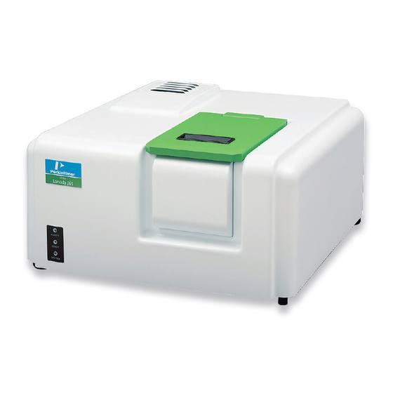
Figure 1 Lambda 365 Changer 8-Cell for Dissolution [P/N: N4104018]
I nstructions
09931465A
PerkinElmer, 710 Bridgeport Avenue,
Shelton, CT06484-4794, U.S.A
Produced in the USA.
Advertisement

Related Manuals for PerkinElmer Lambda 365


Summary of Contents for PerkinElmer Lambda 365
- Page 1 09931465A Lam bda 365 Changer 8-Cell for Dissolution I nstallation I nstructions This instruction sheet describes the installation of this accessory which is used with the Lambda 365 Spectrophotometer. Read these instructions before you install this accessory. NOTE: Contacting P erkinElm er Supplies, replacement parts, and accessories can be ordered directly from PerkinElmer, using the part numbers.
-
Page 2: Dimensions And Specifications
09931465A Dim ensions and Specifications Dim ensions Physical Characteristic Specification Comment Height (mm) 140.5 Width (mm) 134.5 Outline Depth (mm) 356.5 Height (mm) Suitable for the Standard Width (mm) Inner Cell Depth (mm) 12.5 Weight (kg) Specifications Physical Characteristic Specification Comment Space between cells (mm) - Page 3 Configuration of Changer 8-Cell for Dissolution Figure 2 Changer 8-Cell for Dissolution Configuration - Used to fix a cell holder, a base plate or a front plate for Lambda 365. - Spare screws (2 each) are included with the accessory.
- Page 4 09931465A Figure 7. Tubings for cell compartment inside (P/N B2000049) and outside (P/N B2000515) Figure 8. Flow Cell (N4101052) NOTE: Tubings for cell compartment inside (B2000049) and outside (P/N B2000515) and Flow cell (P/N N4101052) must be purchased separately. M anifold and tubing connection 1.
- Page 5 09931465A 3. Connect a red connector of the inside tube (P/N B2000049) to the Out port of the manifold and other white connector of the inside tube (long connector) to the flow cell’s outlet port. Figure 10. Connecting the outlet tube 4.
-
Page 6: Installation
ATTENTION Assurez-vous que l’instrument est éteint lors de l’installation de cet accessoire. 1. Prepare the Lambda 365 Spectrophotometer to install this accessory. 2. Connect the power cord and the communication cable. DO NOT turn on the power of the instrument! 3. - Page 7 09931465A 5. Insert the Changer 8-Cell for Dissolution in the sample compartment. Figure 15. Inserting the Changer 8-Cell for Dissolution into the sample compartment 6. Gently press the Changer 8-Cell for Dissolution to connect the communication port (male) under the bottom of the Changer 8-Cell for Dissolution to the port (female) in the sample compartment. Figure 16.
- Page 8 09931465A 7. Tighten the Changer 8-Cell for Dissolution in the sample compartment with the screws. (The red circles indicate the location of the screws in the figure). Figure 17. Tighten the Changer 8-Cell for Dissolution 8. Attach the plate for calibration on the front plate and tighten the 4 bolts. Figure 18.
- Page 9 09931465A M easurem ent Start the System Self Test after warming up the system for at least 20 minutes. NOTE: 1. Double-click on the UV Express Software folder and select one of the mode for starting. 2. The following message box will be shown. Empty the cell holder and close the lid firmly. Click OK. 3.
- Page 10 09931465A 8. Prepare the manifold with all the tubing connected in Chap. ‘Manifold and tubing connection’ (p4). Figure 20. Manifold with all the tubing connected 9. Insert the tubes and cells through the front cover first and hold the manifold in place. Figure 21.
- Page 11 09931465A 11. Insert flow cells for each position of the multi-cell holder. Figure 23. Inserting flow cells 12. Close the lid. Figure 24. Closing the lid 13. ①Select the Accessory tab and ② Select Multi-cell on Accessory Type, and then click the ③Method Setup button to open the Multicell window.
- Page 12 09931465A 14. Using the button, select cells to be used among the available cells list. Check (√) Multi Baseline or Multi Zero, if it is required to use. And then click OK. Available Cells: Indicate cells that are available for measurement. Using Cells: Shows the cell positions which are selected for measurement.
- Page 13 NOTE: When the Lambda 365 system is powered on again after turned off, the System Self Test need to be performed with the cell holder empty. If you want to have the System Self Test done with a Changer 8- cell Water Jack for Dissolution and manifold installed, follow the procedures below.
- Page 14 09931465A CAUTION Do not start the UV Express software before finishing the initialization of grating. Ne dém arrez pas le logiciel UV Express avant de terminer l'initialisation du réseau. ATTENTION NOTE: Start the System Self Test after warming up the system for at least 20 minutes. 4.
- Page 15 09931465A Figure 28. Inserting No.1 and reference cells into the cell holder 8. And then click New to open a new window. 9. Open Method in the main menu. 10. Measure the sample according to the procedure 13-19 of Measurement section. (page 11) Calibration of M ulti-Cell P osition Calibrate the beam position of the Changer 8-Cell for Dissolution when the Multicell is installed for the first time or beam position is incorrect.
- Page 16 09931465A 2. Select the Calibration tab in the Multicell window. The following dialog box will appear. 3. The functions of the Multicell Calibration are shown as follows. Command Function MultiCell Position Show saved steps about each cell position of the Multi-Cell. Used for moving Multi-Cell position as clicking buttons Multicell Move Used for moving Multi-Cell position using...
- Page 17 09931465A 5. Select MultiCell Calibration , and then the following dialog box will appear. Remove all samples from the Changer 8-Cell for Dissolution (Empty the Changer 8-Cell for Dissolution). 6. Select OK, and then the Multicell calibration will start. The current process of calibration will be shown in the main window.
-
Page 18: Troubleshooting
Troubleshooting W hen the M ulti-Cell does not m ove 1. Check with the connector port. Check if the Changer 8-Cell for Dissolution connector is connected firmly to the Lambda 365. W hen the intensity value is low 1. Recalibrate the Multi-Cell.
Need help?
Do you have a question about the Lambda 365 and is the answer not in the manual?
Questions and answers