PerkinElmer Lambda 365 Installation Instructions Manual
6-position peltier controlled cell changer, controller
Hide thumbs
Also See for Lambda 365:
- User manual (70 pages) ,
- Installation instructions manual (18 pages) ,
- Assembly/installation instructions (18 pages)
Advertisement
Quick Links
Lambda 365 6-Position Peltier Controlled Cell Changer,
This instruction sheet describes the installation of this accessory which is used with the Lambda 365
Spectrophotometer.
Read these instructions before you install this accessory.
NOTE:
Contacting PerkinElmer
Supplies, replacement parts, and accessories can be ordered directly from PerkinElmer, using the part
numbers.
See our website:
http://perkinelmer.com
PerkinElmer's catalog service offers a full selection of high-quality supplies.
To place an order for supplies and many replacement parts, request a free catalog, or ask for
information:
If you are located within the U.S., call toll free 1-800-762-4000, 8 a.m. to 8 p.m. EST. Your order will be
shipped promptly, usually within 24 hours.
If you are located outside of the U.S., call your local PerkinElmer sales or service office.
Features
•
Full software control
•
Liquid cooling system
•
N
gas purging available
2
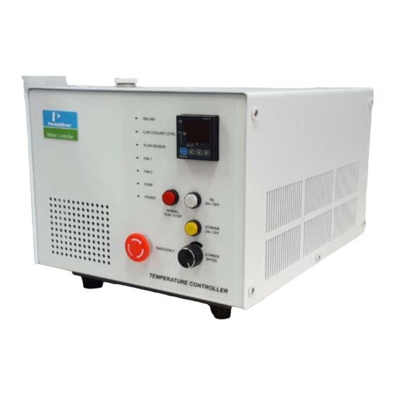
Figure 1 6-Position Peltier Controlled Cell Changer, Controller (with heated
Controller Installation Instructions
reference) [P/N: N4101029] or Peltier Temp Unit (Multi) w/o Reference
Heating [P/N: N4101008]
09931286E
PerkinElmer, 710 Bridgeport Avenue,
Shelton, CT 06484-4794, U.S.A
Produced in the USA.
Advertisement

Subscribe to Our Youtube Channel
Related Manuals for PerkinElmer Lambda 365


Summary of Contents for PerkinElmer Lambda 365
- Page 1 09931286E Lambda 365 6-Position Peltier Controlled Cell Changer, Controller Installation Instructions This instruction sheet describes the installation of this accessory which is used with the Lambda 365 Spectrophotometer. Read these instructions before you install this accessory. NOTE: Contacting PerkinElmer Supplies, replacement parts, and accessories can be ordered directly from PerkinElmer, using the part numbers.
-
Page 2: Dimensions And Specifications
09931286E Dimensions and Specifications Peltier Controller Physical Characteristic Specification Power 100-240 VAC, 50/60 Hz, 300W, Free Voltage Temperature Range -5 to 100°C (Maximum Internal Temperature) Maximum Ambient Operating Temperature 40°C 310 (W) x 410 (D) x 275 (H) mm Dimensions (12.2 (W) x 16.1 (D) x 10.8 (H) in) Weight 20.0 kg (44 lb) -
Page 3: Safety Warnings
09931286E Safety Warnings When this label is attached to an instrument it means refer to the manual. Lorsque cette étiquette est attachée à un instrument, il est nécessaire WARNING de voir le manuel. There is risk of receiving a fatal electric shock if the fuses are replaced with the power cord connected. - Page 4 Waste Basket for Coolant, 1ea Waste Hose for Coolant, 1ea Phillips round head screw with washer, 2ea Description 6-Position Peltier Controlled Cell Changer (with heated reference or without heated reference) Figure 2-1 Lambda 365 6-Position Peltier Controlled Cell Changer (with heated reference)
- Page 5 Cell Lifting knob for reference cell g. Phillips round headscrew with washer Used to fix a cell holder, a base plate or a front plate for Lambda 365. Spare screws (2ea) are enveloped with the accessory. Figure 3 Phillips round headscrew with washer (M4 *12L) h.
- Page 6 09931286E Peltier Controller Front View of Peltier Controller Figure 5 Front view a. Manual touch pad with Display: Temperature Control Unit (Heating/Cooling Block). b. LED Indicators: Display the status of the operation of Coolant Circulation, Fan, Pump, etc. (If there is any problem in the components, Red LED will flash with beep alarm.). c.
- Page 7 09931286E Rear View of Peltier Controller Figure 6 Rear view a. RS-232 port b. AC Power: Main Power ON/OFF c. Fuse: AC socket + Fuse Holder d. Interface: Interface cable for connecting with 6-Position Peltier Controlled Cell Changer e. Air Vent Manual button: It is used for removing the air in the coolant hose. Buzzer: It makes an alarm sound.
-
Page 8: Installation
‘H’(high) mark in the scale on the left side of the Peltier Controller. When the coolant is running short for the operation, LED of Low Water Level is changed red with alarm sounding. Connect the power cord and communication cable of the Lambda 365. DO NOT turn on the power of the instrument! - Page 9 09931286E Remove the two Phillips round head screws with washer (M4*12L) to disassemble the existing cell holder and base plate. Figure 8 Location of Phillips round head screws with washer Pull out the cell holder and base plate by hand. Figure 9 Pulling out the cell holder and base plate Insert the 6-Position Peltier Controlled Cell Changer in the sample compartment.
- Page 10 09931286E Gently press the 6-Position Peltier Controlled Cell Changer to connect the communication port (male) under the bottom of the 6-Position Peltier Controlled Cell Changer to the port (female) in the sample compartment. Figure 11. Connecting the communication ports Fix and tighten the 6-Position Peltier Controlled Cell Changer with the Phillips round head screws. Figure 12 Location of screws (with heated reference or without heated reference)
- Page 11 09931286E 10. Connect the accessory interface cable of the Peltier Controller to the interface connector of the 6- Position Peltier Controlled Cell Changer. Figure 13 Connecting the accessory interface cable of the Peltier Controller 11. Connect the coolant inlet/outlet and N gas tube between the Peltier Controller and the 6-Position Peltier Controlled Cell Changer.
- Page 12 09931286E 13. Connect the Temperature Probe to the Interface slot for Temperature Probe. Figure 16 Connecting the temperature probe 14. Stuff the probe line into the cell compartment and close the lid of the Interface slot for Temperature Probe. Figure 17 Stuffing the probe line into the cell compartment 15.
- Page 13 16. Connect the power cord to the Peltier Controller. Figure 19 Connecting the power cord 17. Turn on the AC power switch of the Lambda 365 and the Peltier Controller. The air vent manual button should be off before turning on the main power of the...
- Page 14 09931286E Figure 21 Location of Power LED If you hear the alarm sound during the operation, push the emergency CAUTION switch to stop all functions immediately and check the status of Peltier Controller carefully. Then, turn the switch to the right again when everything is solved properly and the functions will be on again.
- Page 15 When using the USB to RS-232 cable, USB to RS-232 Driver has already been installed when installing the Lambda 365 and UV Express software, user does not need to install it again. When the communication by the USB to RS-232 converter is not established, change the port setting as follows;...
- Page 16 09931286E Select Ports (COM & LPT) to expand the listing. These are the devices currently connected to the COM ports. USB Serial Port (COMx) is listed when the driver installation is completed successfully. Double click on the USB Serial Port (COMx) of the Ports (COM & LPT). 5.
- Page 17 09931286E Change the parameter values as shown below. Select OK after checking the changed parameter values. If the Peltier controller fails to communicate with the PC, change the COM Port Number by the following steps. Open Advanced Setting for COMx window again by repeating the steps 1 to 6.
- Page 18 09931286E Select the COM Port number list to expand it and change the COM port number to another one which is not in use from COM 1 to COM 10. 11. Make sure that the changed COM Port Number is applied, and select OK. 12.
- Page 19 09931286E Measurement Thermal Denaturation Mode Install the 6-Position Peltier Controlled Cell Changer referring to the chapter Installation. Close the sample compartment cover and turn on the instrument. Before System Self Test is performed, the 6-Position Peltier Controlled Cell Changer should be installed. NOTE: Otherwise, the instrument can be damaged electrically and do not operate properly.
- Page 20 09931286E a. Y Unit: Select one of the display unit: Absorbance, Transmittance, Reflectance or Energy. b. SBW (nm): Select bandwidth. There are five bandwidths selectable: 0.5, 1, 2, 5 or 20 nm. c. Tm Method: Select a method for determining melting temperature. Options include: 1st derivative and Average.
- Page 21 09931286E Select Connection Check, then Method Setup will be activated. Select Method Setup. Check the communication between Computer and Peltier Controller referring to the chapter NOTE: Setting USB to RS-232 Cable (p15) if the Method Setup is not activated. The Peltier window will be shown. Select the Multi Cell Peltier tab and set parameters according to the experiment conditions.
- Page 22 09931286E b. Using Cells Show the cell positions which are selected for measurement. Remove the cells by switch positions by keys. c. Multi Zero If checked, zero will be measured all the selected positions. If not, zero will be only measured at the 1 cell position among the using cells.
- Page 23 09931286E After completing the parameter setup, select Apply and OK. Then the LED for ON-LINE is turned on, and it will start heating up or cooling down to the Start temperature in the Multicell Peltier tab. Insert blank solutions into the both reference and sample cell holder. Select Baseline and then baseline will be measured when it reaches the set Start Temperature.
- Page 24 09931286E g. Error Range (°C): It shows the temperature tolerance between the sampling and monitored temperature. The measurement will start when the temperature tolerance reaches within the set Error Range. h. Hold Time: It shows the set holding time. i. Elapsed time (s): It shows the elapsed time to reach the sampling temperature. j.
- Page 25 09931286E When the 6-Position Peltier Controlled Cell Changer is connected for the first time, you need to correct NOTE: the cell position. Calibrate the beam position of the 6-Position Peltier Controlled Cell Changer referring to the chapter Calibration of Multi-Cell Position (p30). 6.
- Page 26 09931286E 8. Select Connection check, the Method Setup will be activated. Select Method Setup. Check the communication between Computer and Peltier Controller referring to the chapter Setting NOTE: USB to RS-232 Cable (p15) if the Method Setup is not activated. 9.
- Page 27 09931286E b. Using Cells Show the cell positions which are selected for measurement. Remove the cells by switch positions by keys. c. Multi Zero, Multi Baseline If checked, zero (baseline) will be measured all the selected positions. If not, zero (baseline) will be only measured at the 1 cell position among the using cells.
- Page 28 09931286E 11. Insert blank solutions into the both reference and sample cell holder. Select Baseline (or Zero) and then baseline (or zero) will be measured when it reaches the set Temperature. To monitor the probe temperature, the probes should be immersed in the sample, or to use the block NOTE: temperature for monitoring, the cell lid should be closed tightly.
- Page 29 09931286E It shows the temperature tolerance between the sampling and monitored temperature. The measurement will start when the temperature tolerance reaches within the set Error Range. Hold Time: It shows the set holding time. Elapsed Time (s): It shows the elapsed time to reach the sampling temperature. Status: It shows the status of experimental progress.
- Page 30 09931286E Calibration of Multi-Cell Position Calibrate the beam position of the 6-Position Peltier Controlled Cell Changer when the Multi-Cell is NOTE: installed for the first time or beam position is incorrect. 1. Execute one measurement mode of UV Express software (Scan, for example) and open the Method Setup of the Multi-Cell Peltier.
- Page 31 09931286E 3. The Functions of the Multi-Cell Calibration are shown as follows. Command Function MultiCell Position It shows saved steps of each cell position of the Multi-Cell. It is used for moving Multi-Cell position as clicking buttons Multicell Move It is used for moving Multi-Cell position using buttons by entered step.
- Page 32 09931286E 6. Then the Multi-Cell calibration will start. The current process of calibration will be shown in the main window. 7. When calibration is finished, the following box appears. Click OK. 8. Click Save Result to save the result. If the following message box appears, click OK.
- Page 33 09931286E Peltier Controller Auto Tuning Setup Peltier controller can be compatible with various peltier cell holders (Single or Multi). Whenever you NOTE: exchange the existing peltier cell holder to another one, you should perform the “AUTO TUNING” set up to minimize the temperature fluctuation at the target temperature. 1.
- Page 34 09931286E 5. Push the button (OFF ON). 6. Press the SET/ENT button, and then the MAN LED will blink. 7. The MAN LED will be off after a few minutes. 8. Push the Manual Button (Stop) and then the light is off.
-
Page 35: Troubleshooting
09931286E Troubleshooting Power LED is not lit on 1. Check the connection of the power cord or the fuse. The fuse is located at the rear of the instrument. There is risk of receiving a fatal electric shock if the fuses are replaced with the power cord connected. - Page 36 2. Push the Air Vent Manual button to be switched on and check if coolant flows properly for about one minute after the error occurs. If the Pump LED is continuously on with the alarm sounding, contact your PerkinElmer Service representative. Connection is failed 1.
- Page 37 6-Position Peltier Controlled Cell Changer does not move 1. Check if the 6-Position Peltier Controlled Cell Changerconnector is connected to the Lambda 365. 2. Turn on and off again the Lambda 365 with installed 6-Position Peltier Controlled Cell Changer. Intensity is too low 1.
- Page 38 09931286E...
Need help?
Do you have a question about the Lambda 365 and is the answer not in the manual?
Questions and answers