PerkinElmer Lambda 265 Installation Instructions Manual
Peltier controlled singlecell, with peltier controller
Hide thumbs
Also See for Lambda 265:
- User manual (61 pages) ,
- Assembly/installation instructions (18 pages) ,
- User manual (66 pages)
Table of Contents
Advertisement
Quick Links
Lam bda 265 Peltier Controlled Single Cell,
W ith Peltier Controller I nstallation I nstructions
This instruction sheet describes the installation of this accessory which is used with the Lambda 265
Spectrophotometer.
Read these instructions before you install this accessory.
NOTE:
Contacting P erk inElm er
Supplies, replacement parts, and accessories can be ordered directly from PerkinElmer, using the part
numbers.
See our website:
http://perkinelmer.com
PerkinElmer's catalog service offers a full selection of high-quality supplies.
To place an order for supplies and many replacement parts, request a free catalog, or ask for information:
If you are located within the U.S., call toll free 1-800-762-4000, 8 a.m. to 8 p.m. EST. Your order will be
shipped promptly, usually within 24 hours.
If you are located outside of the U.S., call your local PerkinElmer sales or service office.
Features
•
Easy to install
•
Full software control
•
Liquid cooling system
•
N2 gas available
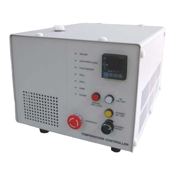
Figure 1. Lambda 265 Peltier control Single Cell [P/N: N4103005] and peltier
temperature controller [P/N: 4100040]
09931228D
PerkinElmer, 710 Bridgeport Avenue,
Shelton, CT 06484-4794, U.S.A
Produced in the USA.
Advertisement
Table of Contents

Related Manuals for PerkinElmer Lambda 265


Summary of Contents for PerkinElmer Lambda 265
- Page 1 Lam bda 265 Peltier Controlled Single Cell, W ith Peltier Controller I nstallation I nstructions This instruction sheet describes the installation of this accessory which is used with the Lambda 265 Spectrophotometer. Read these instructions before you install this accessory.
-
Page 2: Dimensions And Specifications
09931228D Dim ensions and Specifications Dimensions of Peltier Controller Physical Characteristic Specification Power 100-240 VAC, 50/60 Hz, 300W, Free Voltage Temperature Range -5 to 100°C (Maximum Internal Temperature) Maximum Ambient Operating Temperature 40°C Dimensions 310(W) x 410(D) x 275(H) mm Weight 20.0 Kg Coolant Volume... -
Page 3: Safety Warnings
09931228D Safety W arnings When this label is attached to an instrument it means refer to the manual. WARNING Lorsque cetteétiquette est attachéeà un instrument, il est nécessaire de voir le manuel. See the following figure for the location of warning labels on the back of the instrument: Warning To prevent electrical shock, do not open cover. - Page 4 09931228D Description Peltier Controlled Single Cell Figure 1 Lambda 265 Peltier Controlled Single Cell a. Interface connector between Peltier Controlled Single Cell and Peltier Controller b. Coolant Inlet/Outlet Quick Coupler c. N Gas fitting d. Interface slot for Temperature Probe e.
-
Page 5: Led Indicators
09931228D Front View of Peltier Controller Figure 3 Front view of Peltier Controller a. Manual touch pad with Display:Temperature Control Unit (Heating/Cooling Block) b. LED Indicators Display the status of the operation of Coolant Circulation, Fan, Pump, etc. (If there is any problem in the components, Red LED will flash with a beep alarm.). -
Page 6: Configuration Of The Equipm Ent
09931228D R ear View of Peltier Controller Figure 4 Rear view of the Peltier Controller a. RS-232 port b. AC POWER: Main Power ON/OFF c. Fuse: AC socket + Fuse Holder d. Interface: Interface cable for connecting with Peltier controlled Single Cell e. -
Page 7: Installation
Assurez-vous que l’instrument est éteint lors de l’installation de cet accessoire. Place the Lambda 265, Peltier controller and Peltier controlled single cell in a location that is compatible with the required environmental conditions for the operation. Open the lid of the coolant inlet on top of the Peltier controller. - Page 8 09931228D NOTE: Keep the amount of liquid coolant to the level where the indicator is located between the L (low) and H (high) mark in the scale on the left side of the Peltier Controller. When the coolant is running short for the operation, LED of low water level is changed to red with an alarm sounding.
- Page 9 09931228D Connect the accessory interface cable of the Peltier controller to the interface connector of the Peltier controlled single cell. Figure 8 Connecting the accessory interface cable of the Peltier Controller to the interface connector Connect the coolant inlet/outlet and N gas tube between the Peltier controller and the Peltier controlled single cell.
- Page 10 09931228D Connect the temperature probe to the interface slot of the Peltier controlled single cell. Figure 10 Connecting the temperature Probe to the interface slot of the Peltier Controlled Single Cell Setting the Connect the Peltier controller with the PC via the RS-232 or USB to RS-232 cable. See USB to RS-232 Port on page 15 for port settings when you use the USB to RS-232.
- Page 11 ATTENTION contrôleur Peltier ne soit mis sous tension et pendant le fonctionnement de ce dernier afin d'éviter qu'une erreur de communication entre le Lambda 265 et le contrôleur Peltier ne se produise. Check that the Power LED is on as a blue light.
- Page 12 09931228D 1. Push the Manual button on the control panel of the peltier controller then button light is on. 2. Set any SP temperature between 30~37°C using the button. 3. Press and hold the SET/ENT button until shown “G.AT”. 4. Push the SET/ENT button again.
- Page 13 09931228D 5. Push the button (OFF ON). 6. Press the SET/ENT button, MAN LED will blink. 7. MAN LED will be off after few minutes. 8. Push Manual Button (Stop) and then light is off.
- Page 14 09931228D If you hear the alarm sound during the operation, push the emergency switch to CAUTION stop all functions immediately and check the status of Peltier Controller carefully. Then, turn the switch to the right again when everything is solved properly and the functions will be on again.
- Page 15 09931228D Setting USB to RS-232 P ort Use the following procedure to change the port setting when communication is not connected by using USB to RS-232 convert. Select My Computer -> Properties. Select Device Manager.
- Page 16 09931228D Select Ports (COM & LPT) to expand the listing. These are the devices currently connected to the COM ports. USB Serial Port (COMx) is visible when the driver installation is completed successfully. Double click on USB Serial Port (COMx) of the Ports (COM & LPT) section.
- Page 17 09931228D Select the Port Settings tab and click on the Advanced… button. Change the parameter values as shown below.
- Page 18 09931228D Select OK after checking the changed parameter values. If the Peltier controller fails to communicate with the PC, change the COM Port Number in the following steps. Open Advanced Setting for COMx window following steps 1 to 6 in this procedure. Select the COM Port number list to expand it and change the COM port number another one which is not in use from COM 1 to COM 10.
- Page 19 09931228D Make sure that the changed COM Port Number is applied, and select OK. After the port setting is changed, restart the computer. M easurem ent This accessory can be operated in the Temperature Based Kinetics in the Kinetics mode and Thermal Denaturation in the Bio Analysis mode.
- Page 20 09931228D The following dialog box will be displayed. Setup test parameters as follows; a. Edit Heating (Cooling) Rate (°C/min): Set the heating (cooling) temperature rate in each temperature range. Sample is measured whenever it reaches the set temperature by the Rate (°C/min), and the sample is also measured at the Start Temperature and the End Temperature.
- Page 21 09931228D NOTE: Calculation Start Temperature and Calculation End Temperature must be entered within Start Temperature and End temperature. Select Wavelength Range and enter the wavelength range for the measurement. After setting parameters for Experiment Setup, Baseline Correction and Temperature Based Kinetics, selectOK. Select Single Cell Peltier in the Accessory Type on the main screen of the software.
-
Page 22: Temperature Control
09931228D The Setup Single Cell Peltier window will be shown. Set parameters according to the experiment conditions. ▶Temperature Control Temperature(°C): Enter the preset temperature for the experiment. NOTE: Starting the temperature of experiment needs to be set up in the method window. Return to temperature (°C): Enter the returning temperature after the experiment is finished. - Page 23 09931228D After completing the parameter setup, select OK. Then the LED for On-Line is turned on, and it will start heating up or cooling down to the set temperature in the Setup Single Cell Peltier. Select Blank, and then the blank is measured when it reaches the set start temperature. To monitor the probe temperature, the probes should be immersed in the sample, or to use the block NOTE: temperature for monitoring, the cell lid should be closed tightly.
- Page 24 09931228D SP Temp (°C): Shows the current temperature while it goes up / down to the measurement temperature. Block Temp (°C): Shows the temperature of Cell Block. Probe 1 Temp (°C): Shows the temperature of Probe 1. Probe 2 Temp (°C): Shows the temperature of Probe 2. Monitor: Monitored temperature is shown out of Block, Probe 1 and Probe 2.
- Page 25 09931228D The following dialog box will be displayed. Setup test parameters as follows: Edit Heating(Cooling) Rate (°C/min): Set the heating (cooling) temperature rate in each temperature range. Sample is measured whenever it reaches the set temperature by the Rate (°C/min), and the sample is also measured at the Start Temperature and the End Temperature.
- Page 26 09931228D Where, T is the Celsius temperature (°C). Tm method: Select a method for determining Tm (DNA melting temperature). Options include: 1st derivative and Average. DNA Pair Length (K): Enter the DNA base pair length. If a DNA base pair length is above 5000, enter “0”.
- Page 27 09931228D Click on the setup button (pencil icon) in the Experiment Setup on the main screen of the software. Setup Single Cell Peltier window will be shown. Set parameters according to the experiment conditions. ▶Temperature Control a. Temperature (°C) Enter the preset temperature for the experiment. Starting the temperature of experiment needs to be set up in the method window.
- Page 28 09931228D Block: The temperature of Cell Block Probe 1: The temperature of Probe 1 Probe 2: The temaperature of Probe 2 Example: If Block is selected, measurement will start when the temperature of the cell block reaches the setting temperature. ▶Temperature Display Select which temperature will be displayed on the panel: Block, Probe 1 or Probe 2.
-
Page 29: Troubleshooting
09931228D a. Start Temp (°C): Shows the starting temperature of experiment. b. Measurement Temp (°C): Shows the temperature at which the sample will be measured. c. SP Temp (°C): Shows the current temperature while it goes up / down to the measurement temperature. - Page 30 09931228D Turn off and unplug the instrument. Locate the fuse cover on the left rear panel of the instrument. Carefully open the compartment latch where the fuse is located. Location of latch on the fuse compartment door Figure 18. Fuse Disconnect the fuse.
- Page 31 Push the Air Vent Manualbutton to be switched on and check if coolant flows properly for about one minute after the error occurs. If the Pump LED is continuously on with the alarm sounding, contact PerkinElmer. Connection is failed Check whether the Interface connector is lined properly.
- Page 32 09931228D...
Need help?
Do you have a question about the Lambda 265 and is the answer not in the manual?
Questions and answers