Alpha ESS Storion-SMILE-T10 Installation Manual
Energy storage system
Hide thumbs
Also See for Storion-SMILE-T10:
- Installation manual (23 pages) ,
- Installation manual (55 pages)
Table of Contents
Advertisement
Advertisement
Table of Contents

Related Manuals for Alpha ESS Storion-SMILE-T10


Summary of Contents for Alpha ESS Storion-SMILE-T10
- Page 1 Installation Manual Energy Storage System (ESS) Storion-SMILE-T10...
-
Page 3: Imprint
Web: www.alpha-ess.com Add: JiuHua Road 888, High-Tech Industrial Development Zone 226300 Nantong City, Jiangsu Province Australia Alpha ESS Australia Pty. Ltd. Tel.: +61 1300 968 933 E-mail: australia@alpha-ess.com Web: www.alpha-ess.com.au Add: Suite 1, Level 1, 530 Botany Road, Alexandria, NSW, 2015 Italy Alpha ESS Italy S.r.l. -
Page 4: Copyright Statement
Copyright Statement Copyright Statement This manual is under the copyright of Alpha ESS Co., Ltd. with all rights reserved. Please keep the manual properly and operate in strict accordance with all safety and operating instructions in this manual. Please do not operate the system without read- ing through the manual. -
Page 5: Table Of Contents
3.2 Switch off ....................... 35 EMS Introduction and Set up ................36 4.1 Function Description ..................36 4.2 Setting ......................37 4.3 EMS Communication Checking ..............40 4.4 Assembling of the Front Panels ..............41 ___________________________________________________________________ Alpha ESS Co., Ltd. Page III of 46... - Page 6 Your Smart Energy Content Online Monitoring ....................41 Annex........................44 6.1 Datasheet – AlphaESS Storion-SMILE-T10 ..........44 ___________________________________________________________________ Alpha ESS Co., Ltd. Page IV of 46...
-
Page 7: Introduction
Your Smart Energy Introduction Introduction 1.1 System Introduction AlphaESS Storion-SMILE-T10 (incl. M4856-S, HV50056 and SMILE-T10-INV) can be applied in DC-coupled systems (mostly new installation), AC-coupled systems (mostly retrofit) and Hybrid-coupled systems (mostly retrofit, and PV capacity-increase), as the following scheme: Figure 1 DC-coupled Storage System –... -
Page 8: General Precautions
During standard operation, no electrolyte shall leak from the battery pack and no toxic gases shall form. Despite careful construction, if the Battery Pack is damaged or a fault occurs, it is possible that electrolyte may be leaked or toxic gases formed. ___________________________________________________________________ Alpha ESS Co., Ltd. Page 6 of 46... - Page 9 Do not move the system when it is already connected with battery modules. Secure the system to prevent tipping with restraining straps in your vehicle. The transportation of AlphaESS Storion-SMILE-T10 must be made by the manufacturer or an instructed personal. These instructions shall be recorded and repeated.
-
Page 10: Parts List
Positive X2, negative Bracket A (X1) Bracket B (X1) ADL3000 or ACR10R (X1) M4856-S Screw package: PE Protective bag Battery pack (X1) Screw M5*10(X4) Expansion tube (X4) Gasket (X4) (X1) Expansion screw (X4) ___________________________________________________________________ Alpha ESS Co., Ltd. Page 8 of 46... - Page 11 (X1) Gasket (X5) (X12) Expansion screw (X5) Negative power cable (X1) Quick Installation Terminal resistance Hexagon nuts with User Manual (X1): Cable bond (X1) Manual (X1): (X1) flange (X4) M4856-S&HV50056 M4856-S&HV50056 ___________________________________________________________________ Alpha ESS Co., Ltd. Page 9 of 46...
-
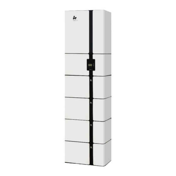
Page 12: System Appearance
Your Smart Energy Introduction 1.4 System Appearance Figure 4 Storion-SMILE-T10 Delivery Scope Object Description Hybrid Inverter with Cable Box HV50056 (High-voltage Control Box) M4856-S (BAT1) M4856-S (BAT2) M4856-S (BAT3) M4856-S (BAT4) 1.4.1 Battery ___________________________________________________________________ Alpha ESS Co., Ltd. Page 10 of 46... - Page 13 1.4.1.2 LED Display In normal condition, LED display three status: Status Normal Protection Fault LED Display Green light blinks for Red light blinks for Red and green light 1sec 1sec blink for 1sec ___________________________________________________________________ Alpha ESS Co., Ltd. Page 11 of 46...
-
Page 14: Hv50056
Dip Switch AC Auxiliary Input Dry Contact Inv- LCD Screen Inv+ LED Indicator LAN COM Port Molded Case Circuit Breaker (MCCB) EMS Meter Communication Port AC Switch (For AC Auxiliary In- put) ___________________________________________________________________ Alpha ESS Co., Ltd. Page 12 of 46... -
Page 15: Inverter Cable Box
The maintenance procedures relating to the product have not been followed to an acceptable standard; Force majeure (violent or stormy weather, lightning, overvoltage, fire etc.); Damages caused by any external factors. ___________________________________________________________________ Alpha ESS Co., Ltd. Page 13 of 46... -
Page 16: Installation
sites that are higher than 3000 meters above the sea level; sites with explosive atmosphere; sites with direct sunlight; sites with extreme change of ambient temperature; wet rooms; sites with highly flammable materials or gases; or ___________________________________________________________________ Alpha ESS Co., Ltd. Page 14 of 46... -
Page 17: Restricted Locations
Where more than 4 batteries are installed, some batteries shall be installed beside, distance between two rows batteries shall be not less than 100 mm SMILE-T10 shall be mounted with the highest point no greater than 2.2 m above the floor or platform. ___________________________________________________________________ Alpha ESS Co., Ltd. Page 15 of 46... -
Page 18: Installation
Figure 11 Removing Front Panel Step 2: Pull the buckle from the bottom right in the middle and pull the top two guide rods to remove the front panel. ___________________________________________________________________ Alpha ESS Co., Ltd. Page 16 of 46... - Page 19 Please drill four holes (two on each side) directly on the wall at the marking positions of the brackets with an impact drill (bit φ 8.0mm, length 20cm), and the depth of each hole is about 7 cm. ___________________________________________________________________ Alpha ESS Co., Ltd. Page 17 of 46...
- Page 20 Step 7: Take the HV50056 out of the packaging box. Pull out the top two guide rods and remove the front panel. Remove the rear bracket from the HV50056, as shown in Figure 15. ___________________________________________________________________ Alpha ESS Co., Ltd. Page 18 of 46...
- Page 21 (bit φ 8.0mm, length 20cm), and the depth each hole is about 7 cm. Please insert the expansion tube into the drilled hole. Pass the tapping screw through the gasket and lock with a screwdriver, as Figure 17 shows. ___________________________________________________________________ Alpha ESS Co., Ltd. Page 19 of 46...
- Page 22 (bit φ 8.0mm, length 20cm), and the depth of each hole is about 7 cm. Please insert the expansion tube into the drilled hole. Pass the tapping screw through the gasket and lock with a screwdriver, as Figure 19 shows. ___________________________________________________________________ Alpha ESS Co., Ltd. Page 20 of 46...
- Page 23 Figure 20 Installation of the HV50056 and the Inverter Step 12: Please hang the HV50056 on the rear bracket of HV50056 and hang the SMILE-T10-INV on the bracket B of the inverter. ___________________________________________________________________ Alpha ESS Co., Ltd. Page 21 of 46...
-
Page 24: Wiring
Step 13: Before wiring please remove the front maintenance baffle of the batteries with an across screwdriver. Figure 21 Connection of Power Cables on Battery Side Step 14: Please connect the power cables as referred in Figure 21 . Figure 22 Battery Power Cable ___________________________________________________________________ Alpha ESS Co., Ltd. Page 22 of 46... - Page 25 M5 nut inside of the battery; The plug connector on the other side shall be connected to the plug port of the HV50056 with the corresponding color. When a crisp sound is heard, the connection is correct. ___________________________________________________________________ Alpha ESS Co., Ltd. Page 23 of 46...
- Page 26 →through the joint and inserted in to the COM port inside of the battery. HV50056 & Battery communication cable connection sequence: the RJ45 connector on one side shall be through the waterproof connector inserted into the COM ___________________________________________________________________ Alpha ESS Co., Ltd. Page 24 of 46...
- Page 27 BAT- port on SMILE-T10-INV. The AC auxiliary power cables which have been prewired onto the inverter, shall be connected to the AC auxiliary port on HV50056, as shown in Figure 26. ___________________________________________________________________ Alpha ESS Co., Ltd. Page 25 of 46...
- Page 28 Step 18: Please pass the cable through the waterproof cap, the sealing ring and the joint on the baffle, and then connect with an RJ45 connector, see Figure 28. Figure 29 Network Cable Type B NOTE: The communication cable is in type B, see 错误!未找到引用源。. ___________________________________________________________________ Alpha ESS Co., Ltd. Page 26 of 46...
- Page 29 COM port of the Inverter with a regular 568B network cable. Figure 31 Connection of PV cables Step 21: Connect the PV MC4 connector to the PV ports of the inverter. ___________________________________________________________________ Alpha ESS Co., Ltd. Page 27 of 46...
- Page 30 Control Box Earthing Point Figure 33 Earthing Points Step 23: Figure 33 shows the earthing points on the HV50056 and cable box. Please connect them to the grounding copper bar of the customer. ___________________________________________________________________ Alpha ESS Co., Ltd. Page 28 of 46...
- Page 31 Note: There should be no same ID number in one cluster. Figure 35 Turning on the Switch Step 25: After wiring, please open the front cover of HV50056 and turn on the molded case circuit breaker. ___________________________________________________________________ Alpha ESS Co., Ltd. Page 29 of 46...
-
Page 32: Power Meter
Meter ADL-3000 (If Applicable) 2.4.1.1 ADL-3000 (without CT, without meter plug), if applicable: A PV meter will be applied in an AC/hybrid system. Figure 36 ADL-3000 Connection (without CT, without Meter Plug) ___________________________________________________________________ Alpha ESS Co., Ltd. Page 30 of 46... - Page 33 2.4.1.2 ADL-3000 (without CT, with meter plug), if applicable: A PV meter will be applied in an AC/hybrid system. Figure 37 ADL-3000 Connection (without CT, with Meter Plug) ___________________________________________________________________ Alpha ESS Co., Ltd. Page 31 of 46...
- Page 34 AC/hybrid system. Figure 38 ADL-3000 Connection (with CT, without Meter Plug) Note: When connecting CTs, pay attention to the current direction. P1 should be nearest to the grid or the PV-inverter. ___________________________________________________________________ Alpha ESS Co., Ltd. Page 32 of 46...
- Page 35 AC/hybrid system. Figure 39 ADL-3000 Connection (with CT, with Meter Plug) Note: When connecting CTs, pay attention to the current direction. P1 should be nearest to the grid or the PV-inverter. ___________________________________________________________________ Alpha ESS Co., Ltd. Page 33 of 46...
-
Page 36: Acr10R Meter (If Applicable)
Your Smart Energy Installation 2.4.2 ACR10R Meter (If Applicable) Figure 40 ACR10R with CT Connection (without Meter Plug) Note: When connecting CTs, pay attention to CT arrow directions, please refer to Figure ___________________________________________________________________ Alpha ESS Co., Ltd. Page 34 of 46... -
Page 37: System Operation
If backup load is applied, turn off the Backup AC breaker. Step 3: Turn off the MCCB of HV50056. Step 4: Turn off the PV switch of the inverter Step 5: Turn off the On-grid AC breaker. ___________________________________________________________________ Alpha ESS Co., Ltd. Page 35 of 46... -
Page 38: Ems Introduction And Set Up
OFF: System is abnormal or warning ON: System is communicated with server Internet OFF: System is not communicated with server Object Name Description Return Button: Escape from current interface Button Function or function ___________________________________________________________________ Alpha ESS Co., Ltd. Page 36 of 46... -
Page 39: Setting
Step 3: Click Solar to set the Solar setting. relevant information. Figure 45 Solar Setting Interface Figure 46 Battery Model Interface Step 4: Set PV capacity. Step 5: Click the Battery Function and check battery type M4856-S. ___________________________________________________________________ Alpha ESS Co., Ltd. Page 37 of 46... - Page 40 Figure 53 Force Charge Setting Interface Figure 54 Force Charge Start Time Setting Step 12: If you want to use force charge, Step 13: Set the charge start time sett Enable here. ___________________________________________________________________ Alpha ESS Co., Ltd. Page 38 of 46...
- Page 41 NOTE: It is needed to set the following 3 parameters for manual mode: IP Address: IP address; Subnet Mask: Subnet mask; Default Gateway: Default gateway; Automatic display one parameter: MAC Address: display MAC Address. ___________________________________________________________________ Alpha ESS Co., Ltd. Page 39 of 46...
-
Page 42: Ems Communication Checking
In an AC/Hybrid mode, the Meter 2 status shows YES, which means normal. In a DC mode, the Meter 2 status shows YES, which means normal. Then EMS can work normally. ___________________________________________________________________ Alpha ESS Co., Ltd. Page 40 of 46... -
Page 43: Assembling Of The Front Panels
So please use the following steps: Open the portal: www.alphaess.com. Enter the username and password, then click “Login” to jump to the home page. There will be a prompt after a failed login. ___________________________________________________________________ Alpha ESS Co., Ltd. Page 41 of 46... - Page 44 Then Click “SIGN UP NOW” to go to the login page. More detailed information can be obtained Online Monitoring Webserver installation Manual. ___________________________________________________________________ Alpha ESS Co., Ltd. Page 42 of 46...
- Page 45 Online Monitoring Click install new system to register the license. Figure 74 System Registering Interface Input S/N, Check Code, License No., Date, Name, and Contact No. to complete the registering process. ___________________________________________________________________ Alpha ESS Co., Ltd. Page 43 of 46...
- Page 46 Your Smart Energy Annex Annex 6.1 Datasheet – AlphaESS Storion-SMILE-T10 System Specification Model Storion-SMILE-T10* Nominal Output Power 10 000 VA Max. DC Input Power 13 000 W Capacity Range 11.5 kWh ~ 23.0 kWh (90% DoD) Battery Chemistry LFP (LiFePO4)
Need help?
Do you have a question about the Storion-SMILE-T10 and is the answer not in the manual?
Questions and answers