Alpha ESS Storion-T30 Installation, Operation & Maintenance Manual
Energy storage system
Hide thumbs
Also See for Storion-T30:
- Operation & maintenance manual (25 pages) ,
- Installation manual (17 pages)

Related Manuals for Alpha ESS Storion-T30


Summary of Contents for Alpha ESS Storion-T30
- Page 1 Installation, Operation & Maintenance Manual Energy Storage System (ESS) Storion-T30...
- Page 3 E-mail: info@alpha-ess.com Web: https://cn.alpha-ess.com/ Add: JiuHua Road 888, High-Tech Industrial Development Zone 226300 Nantong City, Jiangsu Province Australia Alpha ESS Australia Pty. Ltd. Tel.: +61 1300 968 933 +61 1300 968 933 (Technical Support) E-mail: australia@alpha-ess.com Web: https://en.alpha-ess.com/ Add: Suite 1, Level 1, 530 Botany Road, Alexandria, NSW, 2015 Italy Alpha ESS Italy S.r.l.
-
Page 4: Copyright Statement
Copyright Statement Copyright Statement This manual is under the copyright of Alpha ESS Co., Ltd, with all rights reserved. Please keep the manual properly and operate in strict accordance with all safety and operating instructions in this manual. Please do not operate the system without reading through the manual. -
Page 5: Table Of Contents
Electrostatic Protection ..............14 Moisture Protection ............... 14 Minimum Personal Protection Equipment ........14 3. Product Description ................16 System Schematic ................16 Product Appearance ............... 16 Product Characteristics ..............17 __________________________________________________________________________________ Alpha ESS Co., Ltd. Page III of 59... - Page 6 Check Before Operation ..............40 Power-on Procedures ..............40 Android Introduction and Set up ............ 41 Running ................... 41 History ..................... 43 Basic Information ................43 Set Up ..................... 44 Power-off Procedures ..............50 __________________________________________________________________________________ Alpha ESS Co., Ltd. Page IV of 59...
- Page 7 Equipment Cleaning................. 54 Cable, Terminal and Equipment Inspection ........54 7. Troubleshooting ..................56 Battery and BMS troubleshooting ..........56 Error Type ..................56 EMS Troubleshooting..............56 Inverter Troubleshooting ..............56 __________________________________________________________________________________ Alpha ESS Co., Ltd. Page V of 59...
-
Page 9: Introduction
Your Smart Energy Introduction 1. Introduction Brief Introduction This manual applies to the Storion-T30 Li-ion Battery Energy Storage System (BESS) and covers these main aspects: (1) Definition of Parts Introduces the product components of the T30 system. (2) Safety introduction Introduces the product application, operating notes and qualification required of operators of T30 Li-ion battery energy storage system. - Page 10 AC three phase supply to building loads. (4) EMS Module The Energy Management System Module monitors and logs system data, provides Alpha cloud access in turn providing efficient control of battery and inverter. __________________________________________________________________________________ Alpha ESS Co., Ltd. Page 8 of 59...
-
Page 11: Safety Instructions
Refer to the operating instructions. The product must not be disposed of in household waste Storion-T30 will be touchable or operable after minimum 5 minutes of being turned off or totally disconnected, in case of any electrical shock or injury. -
Page 12: Manual Keeping
Do not install the system in any environment with temperature lower than -10° C or higher than 50° C, and humidity over 85%. Do not touch the system with wet hands. __________________________________________________________________________________ Alpha ESS Co., Ltd. Page 10 of 59... -
Page 13: Operator Requirements
Fasten the system to prevent from tipping with restraining straps in your vehicle when transporting. The transportation of AlphaESS Storion-T30 must be carried out by certified logistic company and personal. A certified ABC fire extinguisher with minimum capacity of 2kg must be carried along when transporting. -
Page 14: Operation After Power Failure
Inhalation: Evacuate the contaminated area, and seek medical attention. Eye contact: Rinse eyes with running water for 5 minutes, and seek medical attention. __________________________________________________________________________________ Alpha ESS Co., Ltd. Page 12 of 59... -
Page 15: Fire
The signs should be replaced immediately when damaged. Locating of Safety Warning Signs While installing, maintaining, commissioning or repairing the BESS, to prevent un-authorized personnel causing incorrect operation or an accident, obvious safety signs should be located __________________________________________________________________________________ Alpha ESS Co., Ltd. Page 13 of 59... -
Page 16: Measuring Equipment
Item Notes Work clothes Protective shoes Protective glasses Insulated gloves For touching live parts __________________________________________________________________________________ Alpha ESS Co., Ltd. Page 14 of 59... - Page 17 Notes: When replacing modules, the stacking machine should be used carefully in case that the modules may fall down. All workmen are suggested to wear high-safety and high strength protective shoes to protect their feet. __________________________________________________________________________________ Alpha ESS Co., Ltd. Page 15 of 59...
-
Page 18: Product Description
Your Smart Energy Product Description 3. Product Description The AlphaESS Storion-T30 energy storage system is an on-grid system designed for self- consumption at certain periods or for load shifting. The overall system connection diagram is shown in the Figure 3.1. -
Page 19: Product Characteristics
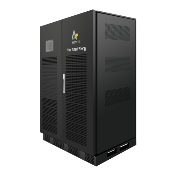
Components BESS Cabinet Android display screen Cabinet door handle Lampstand Inverter Model: Storion-T30-INV Battery management unit (BMU) Model: HV900112 Battery Module M48112-S EMS module Product Characteristics LiFePO4 batteries produced by AlphaESS have a longer lifespan as well as a higher reliability, which is able to satisfy applications of energy storage systems. -
Page 20: Component Parameters
Inverter 3.4.2.1 Product Instruction Storion-T30-INV is an energy storage inverter. It has AC/DC modules. It can transform the grid electricity and charge batteries. The AC/DC module is bidirectional so that the DC electricity from batteries can also be transformed into three-phase AC electricity to supply loads. -
Page 21: __________________________________________________________________________________
Dimension (W x D x H) 440 mm x 550 mm x 173 mm Weight 30kg VDE-AR-N 4105, E DIN VDE V 0124-100, G59/3-2, Grid Regulation AS/NZS 4777.2 Safety IEC 62477-1, IEC62040-1-1, __________________________________________________________________________________ Alpha ESS Co., Ltd. Page 19 of 59... -
Page 22: Battery System
Energy storage capacity situation measured at DC side Continuous discharge current 112 A (1C) DC voltage range 580 ~ 675V(12 Batteries) Communication interface RS485, CAN2.0 3.4.3.1 M48112-S Figure 3.5 Battery appearance __________________________________________________________________________________ Alpha ESS Co., Ltd. Page 20 of 59... -
Page 23: __________________________________________________________________________________
The dip switch of M48112-s defines the serial number. Please see the detailed description in the following table. Table 7 Dip switch definition of M48112-S Serial Serial Serial Dip Switch Dip Switch Dip Switch Number Number Number __________________________________________________________________________________ Alpha ESS Co., Ltd. Page 21 of 59... -
Page 24: __________________________________________________________________________________
Communication mode Weight 62 ± 2.0 kg 490.6 x 611.3 x Size (W x D x H) 159.7(±5) mm Humidity 15%~85% 3.4.3.2 HV900112 HV900112 front cover is as in Figure 3.7 shown. __________________________________________________________________________________ Alpha ESS Co., Ltd. Page 22 of 59... -
Page 25: __________________________________________________________________________________
Working voltage range 200 ~ 900 V Rated current 112 A Dimensions (W x D x H) 494.6 x 552.6 x 162 ± 5mm Weight 20 kg Power consumption <10 W __________________________________________________________________________________ Alpha ESS Co., Ltd. Page 23 of 59... -
Page 26: Installation
1 x 130 mm Power Cable 1 x 2120 mm Power Cable 1 x 2300 mm Power Cable 1 x Communication cable black-black, BAT-HV red-red, BAT-HV black-red, BAT-BAT 2200 mm, BAT-HV900112 __________________________________________________________________________________ Alpha ESS Co., Ltd. Page 24 of 59... -
Page 27: Installation
2 x ADL3000-N/CT 6 x AKH-0.66/K K-30*20 1 X Cable Bond (HUP10-6) 400/5A-NCT For Cabinet Grounding Installation Installation of Cabinet 4.3.1.1 Removing Cabinet Figure 4.1 shows the cabinet Installation position limits __________________________________________________________________________________ Alpha ESS Co., Ltd. Page 25 of 59... -
Page 28: __________________________________________________________________________________
4.3.1.2 Positioning Steps Step1 : Remove the cabinet from the delivery truck using a forklift truck or suitable lifting tool as per Figure 4.2. Note: In an environment with sufficient space. __________________________________________________________________________________ Alpha ESS Co., Ltd. Page 26 of 59... -
Page 29: __________________________________________________________________________________
: Use a forklift or suitable lifting tool to remove the cabinet from the pallet. Step4: Use a forklift or suitable lifting tool to transport the cabinet to the desired installation position. (Figure 4.4) __________________________________________________________________________________ Alpha ESS Co., Ltd. Page 27 of 59... -
Page 30: __________________________________________________________________________________
4 ohms Then fasten the grounding cable (from the accessories package of cabinet) to the grounding bolt using an M6 nut. Wing Nuts M6 Nut Grounding Bolt Figure 4.5 Pushed the baffle __________________________________________________________________________________ Alpha ESS Co., Ltd. Page 28 of 59... -
Page 31: Inverter Installation
Step 2: Check the Battery Number on the cover packaging. Step 3: Put the batteries in the cabinet with the serial number sequence of 01, 02, 03…12 as the above figure shows. __________________________________________________________________________________ Alpha ESS Co., Ltd. Page 29 of 59... -
Page 32: Battery Module Wiring
Figure 4.6. The short cable links for the Battery modules can be found in the Parts Packing list. The long cables are shipped by being tied to the BESS cabinet. __________________________________________________________________________________ Alpha ESS Co., Ltd. Page 30 of 59... -
Page 33: Communication-Cabling
Communication-Cabling Connect the communication cables between Batteries, Battery and HV900112 following figure in the Figure 4.7. __________________________________________________________________________________ Alpha ESS Co., Ltd. Page 31 of 59... -
Page 34: __________________________________________________________________________________
Note: Please check and make sure that all of the COM ports on the battery packs except the last one in each battery cluster are connected with communication cables, and the COM port on the last battery pack is inserted with a terminal resistance. __________________________________________________________________________________ Alpha ESS Co., Ltd. Page 32 of 59... -
Page 35: Power Meter Installation
Figure 4.10 shows the grid meter connection diagram if PV panels and a PV inverter are not used. The power meter should be fitted behind the grid but before any load. __________________________________________________________________________________ Alpha ESS Co., Ltd. Page 33 of 59... -
Page 36: __________________________________________________________________________________
Figure 4.11. __________________________________________________________________________________ Alpha ESS Co., Ltd. Page 34 of 59... -
Page 37: Connection Of Ct Meter Adl-3000Ct(1) - Grid Side
The communication connections are as shown in Figure 4.9 on previous page as a green dotted line. The communication cable connection process to connect to the EMS is shown in the following steps are as follows: __________________________________________________________________________________ Alpha ESS Co., Ltd. Page 35 of 59... -
Page 38: __________________________________________________________________________________
Step 2: Connect the Meter communication cable between the Meter COM port of EMS board and the power meter as Figure 4.12. Step 3: If you need dispatching functionality, you can insert your dispatching module into the USART4 socket as shown in the Figure 4.12. __________________________________________________________________________________ Alpha ESS Co., Ltd. Page 36 of 59... -
Page 39: Inverter Wiring
HV900112. The auxiliary source line is in parallel with the AC side power line flowing into the inverter. Therefore, even though the auxiliary source line is very small in diameter, it does not pose any danger. __________________________________________________________________________________ Alpha ESS Co., Ltd. Page 37 of 59... -
Page 40: __________________________________________________________________________________
Suggested screw torque: 2.6 N· M. Step 5: Final step is to re-fit the plastic protective cover at the connection point that was removed at step 1. The completed installation of Storion-T30 system is shown in Figure 4.15. __________________________________________________________________________________ Alpha ESS Co., Ltd. -
Page 41: __________________________________________________________________________________
Your Smart Energy Installation Figure 4.15 Completed installation of T30 System __________________________________________________________________________________ Alpha ESS Co., Ltd. Page 39 of 59... -
Page 42: Operation
Figure 5.1 Moulded case circuit breaker in switch-off status Step 2: Turn on the AC air switch of HV900112. If there is an AC main switch, turn it on. Figure 5.2 AC switch in switch-on status __________________________________________________________________________________ Alpha ESS Co., Ltd. Page 40 of 59... -
Page 43: Android Introduction And Set Up
Description System Mode From top to bottom: PV capacity (If PV is connected), battery capacity, inverter capacity, self-consumption rate and self- sufficient rate. System Status (Normal/Fault) Internet Status (Online/Offline) Running Diagram __________________________________________________________________________________ Alpha ESS Co., Ltd. Page 41 of 59... -
Page 44: __________________________________________________________________________________
Internet status interface Figure 5.5 4. Click the field “Network” to switch on or off the internet connection to your storage system. Please make sure your system is connected to the internet. __________________________________________________________________________________ Alpha ESS Co., Ltd. Page 42 of 59... -
Page 45: History
Operation History Figure 5.6 History interface “History” shows 24 hours of historical data for “Load” and “SOC” (State of charge) at a given time Basic Information Figure 5.7 Basic information interface __________________________________________________________________________________ Alpha ESS Co., Ltd. Page 43 of 59... -
Page 46: Set Up
Firmware version its using (2). Set Up 5.3.4.1. Command This section is open for Alpha engineers for after sales service use only. Figure 5.8 Command interface 5.3.4.2. System Figure 5.9 Press “System” __________________________________________________________________________________ Alpha ESS Co., Ltd. Page 44 of 59... -
Page 47: __________________________________________________________________________________
Your Smart Energy Operation Press “System” to enter the system display. Figure 5.10 System interface Figure 5.11 Set-up time interface Press “Time” to set the date, time, zone, then click "Close". __________________________________________________________________________________ Alpha ESS Co., Ltd. Page 45 of 59... -
Page 48: __________________________________________________________________________________
Figure 5.13 Set-up system mode Press “AC/DC” to set the system mode. T30 system only supports the AC Mode, and it can automatically identify the type of meter, inverter and battery by the system. __________________________________________________________________________________ Alpha ESS Co., Ltd. Page 46 of 59... -
Page 49: __________________________________________________________________________________
Australian standard. Figure 5.15 Dispatch interface Click "Dispatch" to select the dispatch mode, you can choose between “Remote” and “Local” dispatch.“Remote” is for external control while “Local” is internal (Alpha) control. __________________________________________________________________________________ Alpha ESS Co., Ltd. Page 47 of 59... -
Page 50: __________________________________________________________________________________
If you require a factory reset, click "Factory Reset" and then confirm to start the reset. Note: If you confirm a factory reset all the factory settings are restored, and all data on the system will be cleared. __________________________________________________________________________________ Alpha ESS Co., Ltd. Page 48 of 59... -
Page 51: __________________________________________________________________________________
Customers can select “Self-consumption” mode and ”Grid Charge” mode and ”Controlled Discharge” mode. Choose "Grid Charge" and "Controlled Discharge" to charge and discharge the device according to the time period you need to select. __________________________________________________________________________________ Alpha ESS Co., Ltd. Page 49 of 59... -
Page 52: Power-Off Procedures
Step 1: Open the portal: www.alphaess.com. Step 2: Please fill in “Username”, “Password” and click “Login” if you have already registered. If not, please register by filling in the following webform. __________________________________________________________________________________ Alpha ESS Co., Ltd. Page 50 of 59... -
Page 53: __________________________________________________________________________________
Your Smart Energy Operation Figure 5.20 Monitoring login interface __________________________________________________________________________________ Alpha ESS Co., Ltd. Page 51 of 59... -
Page 54: Registering License
Figure 5.21 Menu for installer Figure 5.22 System registering interface Input S/N (serial number), Check Code, License No., Date, Name, and Contact No. to complete the registering process. __________________________________________________________________________________ Alpha ESS Co., Ltd. Page 52 of 59... -
Page 55: Routine Maintenance
AlphaESS service. Do not replace any components of this equipment without authorization. The company will not bear any warranty or joint liability for the losses caused thereby. __________________________________________________________________________________ Alpha ESS Co., Ltd. Page 53 of 59... -
Page 56: Maintenance Plan
BESS system. Cable, Terminal and Equipment Inspection (Every six months to one year) 1. Check to confirm that cables/wire connections are secure and to the correct torque settings. __________________________________________________________________________________ Alpha ESS Co., Ltd. Page 54 of 59... -
Page 57: __________________________________________________________________________________
7. Check that the grounding/bonding of the equipment is adequate, the grounding/bonding resistance should be less than 4 ohms. __________________________________________________________________________________ Alpha ESS Co., Ltd. Page 55 of 59... -
Page 58: Troubleshooting
This fault is caused by the instantaneous condition of the power network. The inverter will come to Power overvoltage normal in a short time. If the fault still exists, please contact Alpha service __________________________________________________________________________________ Alpha ESS Co., Ltd. Page 56 of 59... -
Page 59: __________________________________________________________________________________
Overload on the AC side of the inverter, need to reduce the load, otherwise the inverter will enter Over-Load into the state of overtime shutdown. If the fault still exists, please contact Alpha service. __________________________________________________________________________________ Alpha ESS Co., Ltd. Page 57 of 59...
Need help?
Do you have a question about the Storion-T30 and is the answer not in the manual?
Questions and answers