Table of Contents
Advertisement
Advertisement
Table of Contents

Related Manuals for Alpha ESS Storion-SMILE-B3


Summary of Contents for Alpha ESS Storion-SMILE-B3
- Page 1 Installation & Operation Manual Energy Storage System (ESS) Storion-SMILE-B3...
- Page 3 Your Smart Energy Imprint Imprint Germany Alpha ESS Europe GmbH Tel.: +49 (0)6103 459 160-1 E-mail: europe@alpha-ess.de Website: www.alpha-ess.de Add.: Paul-Ehrlich-Straße 1a 63225 Langen China Alpha ESS Co., Ltd. Tel.: +86 (0)513 806 868 91 E-mail: info@alpha-ess.com Website: www.alpha-ess.com Add.: Jiu Hua Road 888, High-Tech Industrial Development Zone, Nantong City, 226300, Jiangsu...
-
Page 4: Copyright Declaration
Your Smart Energy Copyright Declaration Copyright Declaration The copyright of this manual is owned by Alpha ESS Co., Ltd. (hereinafter referred to as "AlphaESS") and all rights are reserved. Please keep the manual properly and operate strictly according to all safety and operation instructions in this manual. -
Page 5: Table Of Contents
Your Smart Energy Contents Contents Imprint ............................I Copyright Declaration ......................... II Version Information ........................II Contents ............................III 1. Introduction ..........................5 1.1 Introduction of System ....................5 1.2 General Precautions ....................... 6 2. Installation ..........................8 2.1 Parts List ......................... 8 2.2 System Appearance ....................... -
Page 7: Introduction
3 buttons, friendly human machine interaction system. More importantly SMILE-B3 is stable, safe, and reliable. The normal schematic is as shown in Figure 1.1: Figure 1.1 Storion-SMILE-B3 System with PV NOTE: For the AC coupled system with PV, if only installing Grid CT, the system cannot display PV Inverter generated power, electric energy production etc. -
Page 8: General Precautions
Use strapping if necessary during transportation to prevent tipping. Storion-SMILE-B3 transport must be conducted by the manufacturer or professionals, these operations should be recorded and used. Certified ABC extinguishers with minimum capacity 2 kg must be carried during transportation. - Page 9 Inverters and batteries are heavy and can cause personal injury if the inverter or battery is improperly lifted or dropped during transport or when attached or removed from walls. Lifting and transporting Storion-SMILE-B3 is conducted by more than 1 person. ___________________________________________________________________ Alpha ESS Co., Ltd.
-
Page 10: Installation
1x installation manual 4 x M4*12 screws (100A, 3000:1) (optional) Table 2 Parts List of Battery Expansion Accessory Package Storion-SMILE-B3 Battery Expansion Accessories (Optional) 1 x Positive Power Line 1 x Battery Communication 6 x Screw M5*10 2 x Negative Power Line... -
Page 11: System Appearance
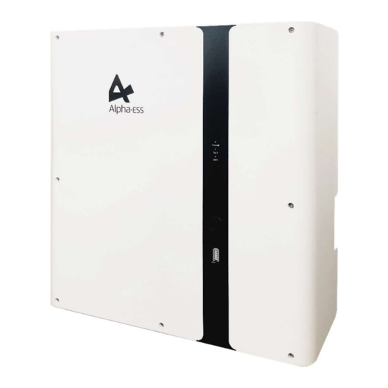
Your Smart Energy Installation 2.2 System Appearance Figure 2.1 Storion-SMILE-B3 External View Table 3 SMILE-B3 System LED Display Status Description Normally on: Normal system operation Single flicker: system standby or self- normal inspection Extinguishing: out-of-order Extinguishing: fault-free fault Normally on: out-of-order... - Page 12 Table 4 SMILE-B3 Battery LED Display LED Outer Ring SOC Status Description Light Flicker Status SOC<5% 5%=<SOC<25% Standby: green light 25%=<SOC<50% flicker 1s work: green light flicker 50%=<SOC<75% 75%=<SOC<95% SOC>95% Figure 2.2 Storion-SMILE-B3 Front View ___________________________________________________________________ Alpha ESS Co., Ltd. Page 10 of 46...
- Page 13 Your Smart Energy Installation 80A battery switch Figure 2.3 Storion-SMILE-B3 Left View Table 5 Ports Definition Name Description Additional battery BMS communicate cable connect DRMs DRED connect port (only for AU) PV CT communicate cable Grid CT communication cable BAT+...
-
Page 14: Limitation Of Liability
Your Smart Energy Installation 2.3 Limitation of Liability AlphaESS shall not be liable directly or indirectly for any product damage or property loss caused by any of the following conditions. The product has been modified, the design modification or the change of parts without the authorization of AlphaESS;... -
Page 15: System Installation
Your Smart Energy Installation 2.4 System Installation This manual introduces the basic steps how to install and set up Storion-SMILE-B3. Observe the specified minimum distance of adjacent objects; Minimum distance guarantee; Sufficient heat dissipation; The upper cover of the energy storage system has enough space to open;... -
Page 16: Installation Tools
Your Smart Energy Installation Place with explosive gases. Place with direct sunlight. Place with the ambient temperature extremely variable. Places with highly flammable materials or gases. Wet rooms Places with potentially explosive gases. Wall loading installation must exceed 180 kg. Note: a ~ e rules are according to AS/NZS5139. -
Page 17: Smile-B3 Installation
Installation 2.4.3 SMILE-B3 Installation Figure 2.6 Open Storion-SMILE-B3 Packaging Step 1: Take out Storion- SMILE-B3 from the packaging box, as shown in Figure 2.6 Figure 2.7 Stand Positioning Step 2: first use the percussion drill (M10 drill) to drill holes in the wall with depth 65mm, then install and place the stand.(1. - Page 18 Installation Figure 2.8 Box Fixation Step 3: install the box of Storion-SMILE-B3 (hold the two handles on the back of B3 and install the B3 box to the stand), as shown in Figure 2.8. In any case, the first step after unpacking is turning off the switch of 63A and 80A.
- Page 19 Your Smart Energy Installation Figure 2.10 Earthing Bonding Position Step 5: the earthing bonding position for Storion-SMILE-B3 is as shown in Figure 2.10, please use the M4*12 screw. Figure 2.11 Backup and Grid Wire Harness Wiring Step 6: Connect Backup and Grid wire harness (to 6 pin terminal strip), as shown in Figure 2.11.
- Page 20 Your Smart Energy Installation Figure 2.12 CT Wire Harness Wiring Step 7: Complete for installing CT, as shown in Figure 2.12. Note: CT communication wires can be connected directly through the silica gel ring of the M20 waterproof contact, no need to make the on-site network line. The maximum outer diameter of the network cable does not exceed 14mm.
- Page 21 Your Smart Energy Installation Step 8: Install ethernet communication cable, as shown inFigure 2.13. It won‘t be needed if using WiFi module. Note: The ethernet communication cable can be connected wiring directly through the silica gel ring of the M20 waterproof contact, no need to make the on-site network cable.
-
Page 22: Battery Expansion
Your Smart Energy Installation 2.4.4 Battery Expansion If you don’t install external M4856-P battery for expansion, please ignore this section. Figure 2.16 Installing stand holders Step 1: Switch off the 63A DC breaker. Open the accessory package and install the two stand holders. Figure 2.17 Installing position limiter Step 2: Install the position limiter on the bottom as shown in Figure 2.17. - Page 23 Your Smart Energy Installation Figure 2.18 Taking out the battery Step 3: Open the battery package. Pull off the buckle located in the middle of the bottom. Pull the top two guide rods to remove the front panel, as shown in Figure 2.18. NOTE: The box must be placed in the direction of the label and only remove the packaging in upwards direction.
- Page 24 Your Smart Energy Installation Step 6: Remove the position limiter NOTE: If the position limiter is not limited, SMILE-B3 can be not removed alone. Step 7: Install the two battery brackets as the above directions. Step 8: Place the battery into the battery holder and fix it with four screws, which have been unscrewed in Step 4.
- Page 25 Your Smart Energy Installation Step 9: Please drill holes directly on the wall at the marking positions of the brackets. Insert the expansion tube and pass the expansion screw through the gasket and lock with a screwdriver. NOTE: If the drill is not long enough, you can mark the hole positions before drilling. Step 10: Remove the maintenance cover before wiring.
- Page 26 Your Smart Energy Installation Step 11: Pass the red positive power cable through the two BAT+ waterproof rings. And fix it on the copper bars inside the battery and inverter. Step 12: pass the black negative power cable through the two BAT+ waterproof rings. And fix it on the copper bars inside the battery and inverter.
- Page 27 Your Smart Energy Installation Step 13: Pass the communication cable through the COM waterproof ring of BAT and BMS waterproof ring of INV. And insert it into the corresponding port (anyone of the two RJ45 port). DIP Switch of B3 63A DC Breaker 63A DC Breaker DIP Switch of M4856-P...
- Page 28 Your Smart Energy Installation If there are more than two batteries to be connected, please refer to DIP switch configuration table as below: Battery DIP 1 DIP 2 DIP 3 DIP 4 DIP Switch Position. Non-bottom battery (incl. B3-bat) Bottom battery Bottom battery is the battery farthest from the inverter.
-
Page 29: Electricity Meter Wiring
Your Smart Energy Installation 2.4.1 Electricity Meter Wiring The power meter should be installed and connected in the distribution box. There are several types of power meters, available for CT, ADL-3000 or ACR10R. CT: 100A, 1:3000 ADL-3000: Three-phase electricity meter (with or without CT) ACR10R: Three-phase CT electricity meter (with CT) Table 6 CT meter ratio and accuracy table Model... - Page 30 Your Smart Energy Installation 2.4.5.2 Electricity Meter ADL-3000 (if optional) ADL-3000 connection (without CT, without Meterplug): Figure 2.20 ADL-3000 connection (without CT, without meterplug) Note: terminal 7, 8 connecting RJ-45 PIN 3, 6. ___________________________________________________________________ Alpha ESS Co., Ltd. Page 28 of 46...
- Page 31 Your Smart Energy Installation ADL-3000 connection (without CT, with Meterplug) Figure 2.21 ADL-3000 connection (without CT, with meterplug) ADL-3000 connection (with CT, without Meterplug) Figure 2.22 ADL-3000 Connection (with CT, without meterplug) ___________________________________________________________________ Alpha ESS Co., Ltd. Page 29 of 46...
- Page 32 Your Smart Energy Installation ADL-3000 Connection (with CT and Meterplug): Figure 2.23 ADL-3000 Connection (with CT and meterplug) Note: In AC system the both two meters' addresses should be set, please refer to 2.4.5.5.1. 2.4.5.3 Electricity meter ACR10R (if optional) Figure 2.24 ACR10R Connection ___________________________________________________________________ Alpha ESS Co., Ltd.
- Page 33 Your Smart Energy Installation Note: please pay attention to the CTs direction. In AC system the both two meter addresses should be set, please refer to 2.4.5.5.2. 2.4.5.4 Mixed Installtion of CT and Meter A CT and a three-phase meter (ADL3000, ALD3000 with CT, ACR10R with CT) can be installed in the same system, the CT and the meter shall be installed according to the corresponding position, otherwise the system will run abnormally.
- Page 34 Your Smart Energy Installation Step 7: Click the "Enter" button and the Step 8: Click the “SET” button to enter the address setting is completed. following interface: Step 9: Click the “SET” button again to enter Step 10: Click the “Enter” button to enter the the save interface: following interface, press the up and down arrow keys, and set “no”...
- Page 35 Your Smart Energy Installation Step 3: On the password input interface, the code Step 4: In the setting interface, select "Comm" is "0001", confirm entering the setting interface; option, enter the communication setting interface; Step 5: Set the communication address and communication baud rate in the communication setting interface.
-
Page 36: Operation
Your Smart Energy Operation 3. Operation Please double check the following before operation. 1. SMILE-B3 is firmly fastened to the mounting bracket on the wall; 2. The polarity of battery wires is correct, battery wires are firmly connected; 3. 80A battery switch: OFF; 4. -
Page 37: Hazards
Your Smart Energy Operation 2. Check the control power supply. If it is OK, return the power supply to find out the reason. 3. Please record every detail related to the fault, so AlphaESS can analyse and solve the fault. Any operation of equipment during a fault is strictly forbidden, please contact Alpha as soon as possible. -
Page 38: Wifi Module Configuration
4. WiFi Module Configuration Please install the WiFi module. Download and install the APP by scanning the QR code (Figure 4.1), and directly connect to Storion-SMILE-B3 by WiFi module. Figure 4.1 AlphaESS-APP Step 1: Open Alpha ESS APP, click the “Wi-Fi Step 2: After that please check whether your configuration”... - Page 39 Your Smart Energy WiFi Module Configuration Step 3: if your mobile phone hasn’t connected to the system hotpot, please open the Wi-Fi network list. Please find the hotpot named after the product SN in WLAN list and connect to it. If the Wi-Fi module is Yilian as shown in Figure 4.7, please enter the password 12345678, otherwise please connect directly.
- Page 40 Your Smart Energy WiFi Module Configuration Step 4: enter the WiFi account and password and then save it, the configuration is successful, click "next", as shown in Figure 4.8 and Figure 4.9. Figure 4.8 WiFi Setting Figure 4.9 Configuration Success Step 5: set the basic parameters, and you can see the details of equipment, click “submit”...
-
Page 41: System Registration
Your Smart Energy System Registration 5. System Registration Installers who haven't yet registered need to click “Register” to visit the registration page. Please refer to “AlphaCloud Online Monitoring Webserver Installers User Manual”, which you can get from AlphaESS sales and get license number from relevant sales from Alpha ESS Log in to your installer account and choose Storage System Maintenance>... -
Page 42: System Setup In Monitoring
5.1 System Setup in Monitoring The system settings of the Storion-SMILE-B3 must be carried in the installer monitoring. To do this, follow the steps below: Step 1: Please login in the installer account, click the list of storage systems and enter the SN. -
Page 43: Inverter Information
Your Smart Energy System Registration Figure 5.1 Interface of Meter Information on Server Step 3: Please select the meter information sub-menu and set the meter configuration. Choose the meter type used and, if necessary, the CT ratio for the grid meter and PV meter individually. After that you must specify whether you have installed a CT or an electricity meter (ADL3000 or ACR10R) and in the case of electricity meters, please further select with or without CT were connected. -
Page 44: Other Information
Your Smart Energy System Registration 5.1.4 Other Information Step 5: Finally, select the "Other Information" submenu and set the following parameter: - ACDC mode: it should be AC mode - Time zone - Data upload frequency: SMILE-B3 has second level data, you can choose it as 10s data if you wish. ___________________________________________________________________ Alpha ESS Co., Ltd. -
Page 45: On-Line Monitoring
Your Smart Energy On-line Monitoring 6. On-line Monitoring 6.1 Account Registration You can create a new account on our webserver for the normal monitoring. In addition, a part of our warranty is based on this connection to our webserver. The data produced prior to registration can be synchronized to the webserver. Please use the following steps: Step 1: Open the portal: www.alphaess.com. - Page 46 Your Smart Energy On-line Monitoring In this form, all fields with a red star are compulsory, and you can select the finally users or installation procedures. *Serial number: EMS serial number (please see the nameplate of the inverter) *Username: 5-15 letters / numbers Note: User name cannot be changed anymore after creation.
Need help?
Do you have a question about the Storion-SMILE-B3 and is the answer not in the manual?
Questions and answers