Alpha ESS Storion-T50 Installation Manual
Energy storage system
Hide thumbs
Also See for Storion-T50:
- Operation & maintenance manual (27 pages) ,
- Installation manual (24 pages) ,
- Manual (5 pages)

Related Manuals for Alpha ESS Storion-T50


Summary of Contents for Alpha ESS Storion-T50
- Page 1 Installation Manual of Energy Storage System (ESS) Storion-T50/T100 ( Indoor , with M38210-S)
-
Page 3: Imprint
Website: www.alpha-ess.com Add.: Jiu Hua Road 888, High-Tech Industrial Development Zone, Nantong City, 226300, Jiangsu Province Australia Alpha ESS Australia Pty. Ltd. Tel.: +61 1300 968 933 E-mail: australia@alpha-ess.com Website: www.alpha-ess.com.au Add.: Suite 1, Level 1, 530 Botany Road, Alexandria, NSW Italy Alpha ESS Italy S.r.l. -
Page 4: Copyright Statement
IMPRINT Copyright Statement This manual is under the copyright of Alpha ESS Co., Ltd, with all rights reserved. Please keep the manual properly and operate in strict accordance with all safety and operating instructions in this manual. Please do not operate the system before reading through the manual. -
Page 5: Table Of Contents
3.1 Appearance of the Product..............11 3.2 Product Characteristics................11 3.3 Parameters of Components..............12 3.3.1. PCS........................12 3.3.2. Battery System....................14 3.3.3. PV Combiner Box (If applicable)..............21 4. Installation......................23 4.1 Installation Precautions................23 4.2 Parts List......................23 ______________________________________________________________________ Alpha ESS Co., Ltd. Page 3 of 48... - Page 6 4.4.4. PV Side-Wiring....................37 4.4.5. AC Side-Wiring....................38 4.4.6. Meter Wiring(On-grid mode)................40 4.4.7. Connect the Communication Cable for the Generator.........42 5. Start-up and Operation..................44 6. Remove the Communication Shorting Screw..........45 7. Contact........................46 ______________________________________________________________________ Alpha ESS Co., Ltd. Page 4 of 48...
-
Page 7: Introduction
Introduction Your Smart Energy 1. Introduction 1.1 Brief Introduction This manual applies for Storion-T50/T100 Li-ion battery energy storage system, mainly includes: (1) Safety introduction Introduces the product use, operating notes and qualification of operators of T50/T100 Li-ion battery energy storage system. - Page 8 (BMS) in which accesses to DC side of a bidirectional converter. (5) Storage unit A combination of a bidirectional converter and a battery system unit, which can be used as an independent load or be controlled directly by monitoring system. ______________________________________________________________________ Alpha ESS Co., Ltd. Page 6 of 48...
-
Page 9: Safety Instructions
Obvious signs should be set at front switch and rear-level switch in case of accidents caused by false switching. Warning signs or tapes should be set near the operation areas. Keys of the system must be pulled out after maintenance or operation. ______________________________________________________________________ Alpha ESS Co., Ltd. Page 7 of 48... -
Page 10: Live Line Measurement
For the safety of operators to the system, personal protective equipment are required. During the operation, following protective equipment are required: Item Notes Work clothes Protective shoes Protective glasses ______________________________________________________________________ Alpha ESS Co., Ltd. Page 8 of 48... - Page 11 Note: When replacing modules, the stacking machine should be used carefully in case that the modules may fall down. All workmen are suggested to wear high-safety and high strength protective shoes to protect their feet. ______________________________________________________________________ Alpha ESS Co., Ltd. Page 9 of 48...
-
Page 12: Product Description
Your Smart Energy Safety Instructions 3. Product Description The AlphaESS Storion-T50/T100 energy storage system supports on-grid mode and off-grid mode to run. The overall system connection diagram is as follows: Figure 3- 1 Application of the system, on-grid mode Figure 3- 2 Applications of the system, off-grid mode ______________________________________________________________________ Alpha ESS Co., Ltd. -
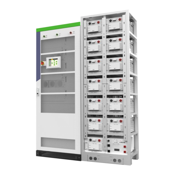
Page 13: Appearance Of The Product
The system has current balance technology between strings in case of circulating current or unbalanced power. ______________________________________________________________________ Alpha ESS Co., Ltd. Page 11 of 48... -
Page 14: Parameters Of Components
3.3.1. PCS 3.3.1.1 Product Instruction Storion-T50/T100-INV is a hybrid inverter. It has DC/DC and DC/AC modules. It can transform the DC electricity from PV panels into three-phase AC electricity to supply loads. The DC/DC module can charge batteries by using the electricity generated by PV panels. The DC/AC module is bidirectional so that the battery can also be charged by the grid through the inverter. - Page 15 Overload Capability 115%~125% 1min; 125%~150% 200ms DC Data (Battery Side) DC Voltage Range 250 – 520 V One-Way Maximum Input 150 A 300 A Current Max. DC Power 50 kW 100 kW ______________________________________________________________________ Alpha ESS Co., Ltd. Page 13 of 48...
-
Page 16: Battery System
Energy storage capacity According to the project Ambient temperature is situation 30℃, measured at DC side Continuous discharge 0.5C (continuous) current Direct voltage 250 ~ 520 V Communication interface RS485, CAN2.0 ______________________________________________________________________ Alpha ESS Co., Ltd. Page 14 of 48... - Page 17 Nominal stored energy 8.1 kWh Work power consumption <2 W Dormant power consumption <100 mW Battery dormant state Max. charge/discharge current 105 A Constant current mode Internal resistance <10 mΩ Factory default ______________________________________________________________________ Alpha ESS Co., Ltd. Page 15 of 48...
- Page 18 AC input (auxiliary power) Earthing point x 4 AC Air switch (auxiliary power) Information label BMU COM port (CAN) x 2 Moulded case circuit breaker LMU COM port (CAN) DCout+ LED light DIP Switch ______________________________________________________________________ Alpha ESS Co., Ltd. Page 16 of 48...
- Page 19 Reserve power supply INV PCS COM port (reserved for RS485) Dry contact COM port PV junction COM port (reserved for RS485) Meter COM port Dry contact COM port (reserved for RS485) ______________________________________________________________________ Alpha ESS Co., Ltd. Page 17 of 48...
- Page 20 Dry contact of generator Dry contact of Fire controller fault (GND) Dry contact of Fire fault (+24V) Reserved Dry contact of Fire controller fault (GND) Dry contact of BMS fault Reserved Reserved ______________________________________________________________________ Alpha ESS Co., Ltd. Page 18 of 48...
- Page 21 Table 11 Wiring definition of the junction box Description Description Top BMU Box 6 x DC OUT INV+ 21 x DC IN BAT- 6 x DC OUT INV- 21 x DC IN BAT+ Table 12 Technical parameters ______________________________________________________________________ Alpha ESS Co., Ltd. Page 19 of 48...
- Page 22 50 kg Max voltage 1000V Max current 300A 3.3.2.5 Battery Rack Figure 3-10 Battery Rac Table 13 Technical parameters 1 Description Technical parameters Dimension(D*W*H) 743.3 x 602 x 2241.5 mm Weight 116kg ______________________________________________________________________ Alpha ESS Co., Ltd. Page 20 of 48...
-
Page 23: Pv Combiner Box (If Applicable)
Figure 3- 51 PV Combiner box Table 14 Wiring definition of the combiner box Description Description PV IN + HALL Sensor Moulded Case Circuit PV IN - Breaker DC OUT+ RS485 DC OUT- ______________________________________________________________________ Alpha ESS Co., Ltd. Page 21 of 48... - Page 24 Your Smart Energy Product Description Table 15 Technical parameters Description Technical parameters Dimension(D*W*H) 160 x 800 x 450 mm Max voltage 1000V Max current(Per string) ______________________________________________________________________ Alpha ESS Co., Ltd. Page 22 of 48...
-
Page 25: Installation
350 mm, BAT-BAT Washer HV900105 4 X M6 1 X Communication Cable 1 X Communication Cable 4 X M6*16 Gouding Serrated 500 mm, BAT-HV Box 2200 mm, HV Box - HV Box Washer ______________________________________________________________________ Alpha ESS Co., Ltd. Page 23 of 48... - Page 26 1system: 1 x 4500 mm, 95mm2 1 system: 1 x 4500 mm, 7500 mm EMS-INV Power Cable, 95mm2 Power Cable, Black-Black, For Junction box- Red-Red, For Junction box - INV(T100) INV(T100); Battery Rack ______________________________________________________________________ Alpha ESS Co., Ltd. Page 24 of 48...
- Page 27 1 x Installation PV Combiner box(If applicable) -AC/Hybrid) Outline size 2 x Meter with 6 CT (on-grid manual (W*H*D):90*14*40mm mode -AC/Hybrid) Through size (a*e) :20*30mm 1 x Operation and maintenance manual ______________________________________________________________________ Alpha ESS Co., Ltd. Page 25 of 48...
-
Page 28: Installation
A≥ 1,000mm, make sure that the front door of the cabinet can be fully opened and there is sufficient space for cold air to enter. Users can conveniently insert and extract the module and operate the breaker. ______________________________________________________________________ Alpha ESS Co., Ltd. Page 26 of 48... - Page 29 When the cabinet is fixed to the concrete floor, make holes on the floor and fix the cabinet to the concrete floor with expansion screws, as shown in Figure 4- 5. ______________________________________________________________________ Alpha ESS Co., Ltd. Page 27 of 48...
-
Page 30: Battery System Installation
4.3.2.2 Battery Installation Figure 4-7 Battery lable inf ormation Figure 4-6 Battery packages Step1: Open all the battery Step 2: Check the Battery Type and Cluster No. on packages. the battery lable. ______________________________________________________________________ Alpha ESS Co., Ltd. Page 28 of 48... - Page 31 Step 4: After completing one rack, please check whether the installed batteries have the same cluster No. Step 5: If there are more than one rack, please repeat step 3 and 4 to install the other battery racks as below Figure shows. ______________________________________________________________________ Alpha ESS Co., Ltd. Page 29 of 48...
-
Page 32: Wiring
HV900105 parts list. D. Connect HV900105 (COM Port) to TOP BMU box (COM Port, Port 1 or 2) by using the communication cable from TOP BMU part list. Please see Figure 4- 12. ______________________________________________________________________ Alpha ESS Co., Ltd. Page 30 of 48... - Page 33 (Port 05 and Port 06) to the PCS (Port 1 and Port 2 ) by using the RS485 cable from the parts list as Figure 4- 13 shows. ______________________________________________________________________ Alpha ESS Co., Ltd. Page 31 of 48...
- Page 34 G. The last COM port of HV900105 which has no cable to connect should be inserted with the terminal resistance from HV900105 parts list. You can see the detailed information as Figure 4- 14 shows. ______________________________________________________________________ Alpha ESS Co., Ltd. Page 32 of 48...
- Page 35 The battery DC positive and negative port of HV900105 can be directly connected to the BAT+ and BAT- of Junction box as Figure 4-15 shows. Figure 4-15 Battery side-power cables connection ______________________________________________________________________ Alpha ESS Co., Ltd. Page 33 of 48...
-
Page 36: Inverter Side-Wiring
The wiring methods should be in accordance with the National Electrical Code or other local standards. Figure 4-17 PCS rack wiring hole and corresponding copper bars Open the dam-board beside the switch and then can see the wiring copper bar as shown below. ______________________________________________________________________ Alpha ESS Co., Ltd. Page 34 of 48... - Page 37 A (Load) Phase A, dimension is shown as below. B (Load) Phase B C (Load) Phase C A (Grid) Phase A B (Grid) Phase B C (Grid) Phase C Phase N Grounding ______________________________________________________________________ Alpha ESS Co., Ltd. Page 35 of 48...
-
Page 38: System Grounding
The grounding of power modules/PCS connection with the rack go through hangers on the module. As for rack grounding, the rack bottom is installed with grounded cooper bars. During wiring, refer to the following table for cable diameter. ______________________________________________________________________ Alpha ESS Co., Ltd. Page 36 of 48... -
Page 39: Pv Side-Wiring
D. Connect the negative pole of storage battery to “DC-” of DC input of DC switch. Confirm wiring firmness. Table 20 DC cable description Rated power Copper DC line section recommendation (mm²) 50kW ≥35 100kW ≥95 The PV connection is shown in Figure 4- 16. ______________________________________________________________________ Alpha ESS Co., Ltd. Page 37 of 48... -
Page 40: Ac Side-Wiring
A(L1)/B(L2)/C(L3) phases of AC output distribution switch of utility grid and PE are respectively connected to A(L1)/B(L2)/C(L3) phases of utility grid and PE. While off-grid mode, A(L1)/B(L2)/C(L3) phases of AC output distribution switch of ______________________________________________________________________ Alpha ESS Co., Ltd. Page 38 of 48... - Page 41 PCS. After wiring, fireproofing mud should be used to seal the wiring holes. Please refer to the following diagram to connect power cables. Figure 4-23 AC-Side wiring diagram, off-grid mode ______________________________________________________________________ Alpha ESS Co., Ltd. Page 39 of 48...
-
Page 42: Meter Wiring(On-Grid Mode)
Figure 4-24 AC-Side wiring diagram, on-grid mode 4.4.6. Meter Wiring(On-grid mode) Please refer to the following diagram to connect the CT meter. Figure 4-25 Schematic diagram of the appearance of the meter ______________________________________________________________________ Alpha ESS Co., Ltd. Page 40 of 48... - Page 43 Meter communication Connect to EMS or other meters through port 2 network cable to realize communication between devices. Figure 4-26 Meter wiring diagram(DC mode) ______________________________________________________________________ Alpha ESS Co., Ltd. Page 41 of 48...
-
Page 44: Connect The Communication Cable For The Generator
1 and 2 (normally open), you can connect the diesel dry contact to control the 1 and 2. Please connect the diesel control dry contact as the below picture shows: ______________________________________________________________________ Alpha ESS Co., Ltd. Page 42 of 48... - Page 45 Installation Your Smart Energy Figure 4-29 Connecting the communication cable for generator Note: normally open/closed contact which connects the Genset according to the genset controller. ______________________________________________________________________ Alpha ESS Co., Ltd. Page 43 of 48...
-
Page 46: Start-Up And Operation
Your Smart Energy Installation 5. Start-up and Operation Please refer to the Operation Manual for details. ______________________________________________________________________ Alpha ESS Co., Ltd. Page 44 of 48... -
Page 47: Remove The Communication Shorting Screw
Figure 6 -1 Remove the communication shorting screw NOTE: Don’t throw away the Communication shorting screw, find a bag and maybe we use it later. ______________________________________________________________________ Alpha ESS Co., Ltd. Page 45 of 48... -
Page 48: Contact
Equipment model Serial number C. Battery type and number, or PV modules number and string type. D. Communication type Firmware version Error number and error message ______________________________________________________________________ Alpha ESS Co., Ltd. Page 46 of 48...
Need help?
Do you have a question about the Storion-T50 and is the answer not in the manual?
Questions and answers