Alpha ESS STORION-T50 Installation Manual
Energy storage system
Hide thumbs
Also See for STORION-T50:
- Installation manual (48 pages) ,
- Operation & maintenance manual (27 pages) ,
- Manual (5 pages)
Table of Contents
Advertisement
Quick Links
Alpha ESS Co., Ltd.
+86 513 806 068 91
info@alpha-ess.com
www.alpha-ess.com
JiuHua Road 888, Nantong High-Tech Industrial
Development Zone, Nantong City, 226300
Alpha ESS Europe GmbH
+49 610 3459 1601
europe@alpha-ess.de
www.alpha-ess.de
Paul-Ehrlich-Straße 1a, 63225 Langen, Hessen
Alpha ESS Australia Pty. Ltd.
+61 402 500 520 (Sales)
+61 1300 968 933 (Technical Support)
australia@alpha-ess.com
www.alpha-ess.com.au
Suite 1, Level 1, 530 Botany Road, Alexandria,
NSW, 2015
Alpha ESS UK Co., Ltd
uk@alpha-ess.com
Drake House, Long Street, Dursley, gl11 4hh
Alpha ESS Suzhou Co., Ltd.
+86 512 6828 7609
info@alpha-ess.com
www.alpha-ess.com
Level 15,SIPC 158 Wangdun Road SIP Suzhou,
215028
Alpha ESS Italy S.r.l.
+39 599 239 50
info@alpha-ess.it
www.alpha-ess.it
Via Loda,17-41013 Castelfranco Emilia(MO)
Alpha ESS Korea Co., Ltd
+82 64 721 2004
korea@alpha-ess.com
2F, 19-4, Nohyeong 11-gil, Jeju-si, Jeju-do,
Republic of Korea
INSTALLATION MANUAL
INSTALLATIONMANUAL
ENERGY STORAGE SYSTEM (ESS)
ENERGYSTORAGESYSTEM(ESS)
Storion-T50/T100
STORION-SMILE-T10(INDOOR)
V03
(Indoor, with M48112-S)
Advertisement
Table of Contents

Related Manuals for Alpha ESS STORION-T50


Summary of Contents for Alpha ESS STORION-T50
- Page 1 INSTALLATION MANUAL INSTALLATIONMANUAL ENERGY STORAGE SYSTEM (ESS) ENERGYSTORAGESYSTEM(ESS) Storion-T50/T100 STORION-SMILE-T10(INDOOR) (Indoor, with M48112-S) Alpha ESS Co., Ltd. Alpha ESS Suzhou Co., Ltd. +86 513 806 068 91 +86 512 6828 7609 info@alpha-ess.com info@alpha-ess.com www.alpha-ess.com www.alpha-ess.com JiuHua Road 888, Nantong High-Tech Industrial...
-
Page 2: Table Of Contents
CONTENTS Copyright Statement INTRODUCTION This manual is under the copyright of Alpha ESS Co., Ltd, with all rights reserved. Please keep the manual properly and operate in strict accordance with all safety and operating instructions 1.1 BRIEF INTRODUCTION in this manual. Please do not operate the system before reading through the manual. -
Page 3: Explanation Of Terms
INTRODUCTION SAFETY INSTRUCTIONS 1.1 Brief Introduction 2.1 Manual Keeping This manual applies for Storion-T50/T100 Li-ion battery energy storage system, mainly This manual contains important information about operating the system. Before operat- includes: ing, please read it very carefully. The PCS should be operated in strict accordance with the description in the manual, in (1) Safety introduction case that it causes damage or loss to equipment, personnel and property. -
Page 4: Measuring Equipment
Do not open the container door if the humidity is larger than 95%. Repair or maintaining activities in wet conditions should be avoided or limited. The AlphaESS Storion-T50/T100 energy storage system supports on-grid mode and off-grid mode to run. The excessive energy generated by the PV will be stored in the 2.9 Operation after Power Failure... -
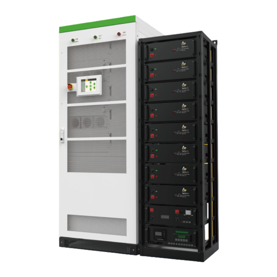
Page 5: Appearance Of The Product
3.3 Parameters of Components 3.3.1 PCS 3.3.1.1 Product Instruction Storion-T50/T100-INV is a hybrid inverter. It has DC/DC and DC/AC modules. It can transform the DC electricity from PV panels into three-phase AC electricity to supply ..loads. The DC/DC module can charge batteries by using the electricity generated by PV panels. -
Page 6: Battery System
Table 3 Technical parameters of the PCS Push the AC breaker into “OFF” position, then turn the AC breaker “ON”. Item Storion-T50-INV Storion-T100-INV AC Side Data (off-grid) Launch the machine and operate it as required AC nominal output power... - Page 7 PRODUCT DESCRIPTION PRODUCT DESCRIPTION 3.3.2.1 M48112-S Table 7 Battery technical parameters: Description Technical parameter Remarks Battery model M48112-S Assembly method 16S2P Figure 3-5 Battery front cover Nominal voltage 51.2 V Voltage range 48~57.6 V Max. charge / discharge Nominal capacity 112 Ah current 1C Nominal stored energy...
- Page 8 PRODUCT DESCRIPTION PRODUCT DESCRIPTION Table 8 HV900112 interface definition: Table 10 Top BMU box with EMS interface definition: Description Description Description Description DCin+ DCout- BMU COM port DIP switch DCin- AC input (auxiliary power) BMU COM port Meter COM port (reserved for RS485) Earthing point x 4 AC Air switch (auxiliary power) Ethernet...
- Page 9 PRODUCT DESCRIPTION PRODUCT DESCRIPTION Table 13 Wiring definition of the junction box: Table 11 Dry contact description Description Description Description Description 6 x DC OUT INV+ Dry contact of Fire controller fault (+24V) Dry contact of generator Dry contact of Fire controller fault (GND) 21 x DC IN BAT- 6 x DC OUT INV- Dry contact of Fire fault (+24V+)
-
Page 10: Pv Combiner Box (If Applicable)
INSTALLATION INSTALLATION 3.3.3. PV Combiner Box (If applicable) Sites with extreme changes of ambient temperature. Sites with highly flammable materials or gases. 4.2 Parts List Table 17 Parts List M48112-S 1 X Power Cable 1 X Communication 4 X M6 420 mm, Black-Red, Cable280 mm, 4 X M6*16... -
Page 11: Installation
INSTALLATION INSTALLATION 1system: 1 x 4500 1 system: 1 x 4500 1 x Operation and mm, 50mm2 Power mm, 50mm2 Power maintenance Cable, Cable, manual 1 cluster: 1 x Red-Red, For Black-Black, For Communication Junction box - Junction box- INV Cable (T50);... -
Page 12: Battery System Installation
INSTALLATION INSTALLATION 4.3.2 Battery System Installation A≥1,000mm, make sure that the front door of the cabinet can be fully opened and there is sufficient space for cold air to enter. Users can conveniently insert and extract the 4.3.2.1 Battery Rack Installation module and operate the breaker. -
Page 13: Wiring
INSTALLATION INSTALLATION Step 4: After completing one rack, please check whether the installed batteries have the To connect the PCS and EMS please open the PCS cabinet front door and remove the same cluster No. and the same battery group No. panel of the right side. -
Page 14: Inverter Side-Wiring
INSTALLATION INSTALLATION 4.4.2. Inverter Side-Wiring Connect the COM port 9 and COM port 10 of TOP BMU box with a regular net cable. Another COM port of HV900112 should be inserted with the terminal residence from The wiring mode of the PCS is down inlet and down outlet, the incoming and outlet HV900112 parts list. -
Page 15: System Grounding
INSTALLATION INSTALLATION 4.4.4. PV Side-Wiring Table 19 PCS wiring copper bars description Use a multi-meter to measure the voltage of PV port, and ensure that the voltage is Position Designation Description within input voltage range of PCS. PV + PV positive port, dimension is shown as below. Disconnect PV switch. -
Page 16: Ac Side-Wiring
INSTALLATION INSTALLATION 4.4.5 AC Side-Wiring 4.4.6 Meter Wiring(On-grid mode) Please refer to the following diagram to connect the CT meter. Ensure that the phase consequence of wires should be a positive consequence. Disconnect AC output distribution switch in PCS. Use a multi-meter to measure and ensure that the cables connected to the terminals are electrically neutral. -
Page 17: Connect The Communication Cable For The Generator
INSTALLATION INSTALLATION Figure 4-26 AC Auxiliary Power Cable Connection Note: The auxiliary power cable bond must be placed above the AC power cable bond. After this please tighten the screw. Figure 4-24 Meter wiring diagram(DC mode) 4.4.7. Connect the Communication Cable for the Generator Figure 4-27 Dry contact of TOP BMU Connect DO_2 to the dry contact of the diesel generator, port 2 and 3 (normally closed contact), 1 and 2 (normally open), you can connect the diesel dry contact to... -
Page 18: Start-Up And Operation
INSTALLATION START-UP AND OPERATION If you have technical problems with our products, please contact the service hotline, START-UP AND OPERATION contact information is under the IMPRINT catalog at the beginning of this manual. Please provide the following information to help you with the necessary assistance: Please refer to the Operation Manual for details.
Need help?
Do you have a question about the STORION-T50 and is the answer not in the manual?
Questions and answers