Alpha ESS STORION-T50 Installation Manual
Energy storage system
Hide thumbs
Also See for STORION-T50:
- Installation manual (48 pages) ,
- Operation & maintenance manual (27 pages) ,
- Manual (5 pages)
Table of Contents
Advertisement
Quick Links
@AlphaEnergyStorageSystem
@AlphaESS
Alpha ESS Co., Ltd.
+86 513 8060 6891
info@alpha-ess.com
www.alpha-ess.com
JiuHua Road 888, High-Tech Industrial Development
Zone 226300 Nantong City, Jiangsu Province
Alpha ESS Europe GmbH
+
49 610 3459 1601
europe@alpha-ess.de
www.alpha-ess.de
Paul-Ehrlich-Straße 1a 63225 Langen
Alpha ESS Italy S.r.l.
+39 599 239 50
info@alpha-ess.it
www.alpha-ess.it
Via Loda,17-41013 Castelfranco Emilia(MO)
Alpha ESS UK Co., Ltd
uk@alpha-ess.com
Drake House, Long Street, Dursley, gl11 4hh
Alpha ESS USA, Inc.
USA@alpha-ess.com
638 S Ahwanee Ter Sunnyvale, California,
94085 United States of America
@alpha_ess
@AlphaESS
www.alpha-ess.com
Alpha ESS Suzhou Co., Ltd.
+86 512 6828 7609
info@alpha-ess.com
www.alpha-ess.com
Building 10-A, Canal Town Industrial Park,
99 Taihu E Rd, Wuzhong District, Suzhou 215000
Alpha ESS Australia Pty. Ltd.
+61 1300 968 933
australia@alpha-ess.com
www.alpha-ess.com.au
Unit 1, 2 Ralph Street Alexandria NSW 2015
Alpha ESS Korea Co., Ltd
+82 64 721 2004
korea@alpha-ess.com
2F, 19-4, Nohyeong 11-gil, Jeju-si, Jeju-do,
Republic of Korea
Alpha ESS International Pte. Ltd.
Singapore@alpha-ess.com
Blk 55 Ayer Rajah Crescent #01-01, Singapore
139949
INSTALLATION MANUAL OF
INSTALLATIONMANUAL
ENERGY STORAGE SYSTEM (ESS)
ENERGYSTORAGESYSTEM(ESS)
STORION-SMILE-T10(INDOOR)
STORION-T50/T100 (INDOOR ,WITH M48112-S)
V02
Advertisement
Table of Contents

Related Manuals for Alpha ESS STORION-T50


Summary of Contents for Alpha ESS STORION-T50
- Page 1 INSTALLATIONMANUAL @AlphaEnergyStorageSystem @AlphaESS @alpha_ess @AlphaESS www.alpha-ess.com ENERGY STORAGE SYSTEM (ESS) ENERGYSTORAGESYSTEM(ESS) Alpha ESS Co., Ltd. Alpha ESS Suzhou Co., Ltd. +86 513 8060 6891 +86 512 6828 7609 STORION-SMILE-T10(INDOOR) info@alpha-ess.com info@alpha-ess.com STORION-T50/T100 (INDOOR ,WITH M48112-S) www.alpha-ess.com www.alpha-ess.com Building 10-A, Canal Town Industrial Park,...
-
Page 2: Table Of Contents
CONTENT Copyright Statement This manual is under the copyright of Alpha ESS Co., Ltd, with all rights reserved. Please INTRODUCTION keep the manual properly and operate in strict accordance with all safety and operating 1.1 Brief Introduction instructions in this manual. Please do not operate the system before reading through the 1.2 Explanation of Terms... -
Page 3: Explanation Of Terms
INTRODUCTION Introduction 4.4.7. Meter Wiring(On-grid mode) 1.1 Brief Introduction 4.4.8. Connect the communication cable for the generator This manual applies for Storion-T50/T100 Li-ion battery energy storage system, mainly START-UP AND OPERATION includes: (1) Safety introduction REMOVE THE COMMUNICATION SHORTING SCREW Introduces the product use, operating notes and qualification of operators of T50/T100... -
Page 4: Safety Instructions
INTRODUCTION SAFETY INSTRUCTIONS (4) Battery system unit Safety Instructions Batteries connected in series/parallel in the pack with a battery management system (BMS) in which accesses to DC side of a bidirectional converter 2.1 Keep the Manual This manual contains important information about operating the system. Before operating, please read it very carefully. -
Page 5: Setting Of Warning Sign For Safety
SAFETY INSTRUCTIONS SAFETY INSTRUCTIONS 2.4 Setting of Warning Sign for Safety 2.10 Minimum Personal Protective Equipment To prevent erroneous operations and accidents caused by unrelated personnel nearby, For the safety of operators to the system, personal protective equipment are required. the suggestions below should be followed during the instruction, maintenance and During the operation, following protective equipment are required: repairing:... -
Page 6: Product Description
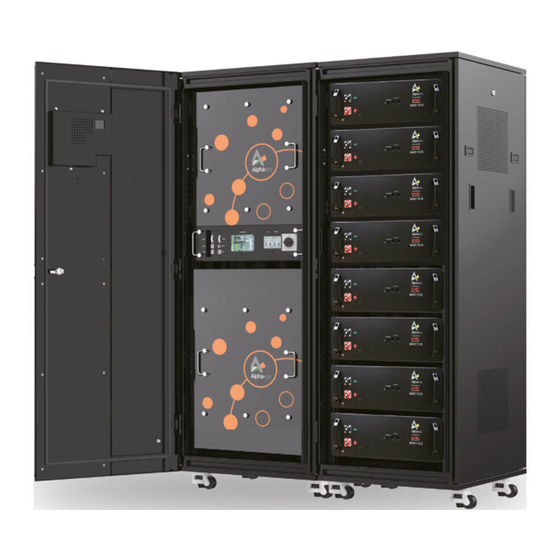
PRODUCT DESCRIPTION PRODUCT DESCRIPTION 3.1 Appearance of the Product Product Description Figure 3-3shows the appearance of the system. The AlphaESS Storion-T50/T100 energy storage system supports on-grid mode and off-grid mode. The overall system connection diagram is as follows: TOP BMU Controller ALPHA CLOUD .. -
Page 7: Parameters Of Components
SPD switch 3.3.1.1 Product Instruction AC breaker (Grid) Storion-T50/T100-INV is a hybrid inverter. It has DC/DC and DC/AC modules. It can transform the DC electricity from PV panels into three-phase AC electricity to supply AC breaker (Load) loads. The DC/DC module can charge batteries by using the electricity generated by PV Battery switch panels. -
Page 8: Battery System
PRODUCT DESCRIPTION PRODUCT DESCRIPTION 3.3.1.4 Emergency Stop Switch Item Storion-T50-INV Storion-T100-INV The PCS stops working immediately after pushing the button. AC Side Data (off-grid) If you want to restart the converter, please follow the process below: Listed: 0.8~1 leading or lagging A. - Page 9 PRODUCT DESCRIPTION PRODUCT DESCRIPTION Table 7 Battery technical parameters: Item Technical parameter Remark Battery model M48112-S Assembly method 16S2P Nominal voltage 51.2 V 48~57.6 V Voltage range Max. charge / discharge Nominal capacity 112 Ah current 1C Figure 3-6 M48112-S front view Nominal stored energy 5.734 kWh Work power consumption...
- Page 10 PRODUCT DESCRIPTION PRODUCT DESCRIPTION 3.3.2.3 Top BMU Box (with EMS) Functions such as remote monitoring, remote upgrade, etc. can be realized through the TOP BMU Box with EMS. 23 24 Figure 3-8 HV900112 front view Table 8 HV900112 interface definition: Figure 3-9 Front view of TOP BMU box with EMS Description Description...
- Page 11 PRODUCT DESCRIPTION PRODUCT DESCRIPTION Description Description Description Description PV junction COM port Air conditioner RS485A port Dry contact of BMS fault Dry contact port Air conditioner RS485B port EMS display screen PCS RS485A port Burning port PCS RS485B port Storage card PV Junction RS485A port Reserved PV Junction RS485B port...
-
Page 12: Pv Combiner Box (If Applicable)
PRODUCT DESCRIPTION PRODUCT DESCRIPTION Table 13 Wiring definition of the junction box: Table 15 Technical parameters: Description Parameter Description Description Dimension(W x D x H) 564 x 667.5 x 2006 mm TOP BMU Box 1 x DC OUT INV+ Weight 120kg 21 x DC IN BAT- 1 x DC OUT INV-... -
Page 13: Installation
INSTALLATION INSTALLATION Installation 4.1 Installation Precautions The following sites are not allowed for installation: A.Sites which are salty and where humid air can penetrate. B.Flooded areas. C.Earthquake areas (additional security measures are required here) . 810.90006-00 810.90004-00 D.Sites that are higher than 3000 meters above the sea level. 1 X Power Cable 1 X Power Cable 2500 mm, Black -... -
Page 14: Pcs Installation
INSTALLATION INSTALLATION 4.3 Installation Battery Rack 4.3.1. PCS Installation 4.3.1.1 Removal When removing the T50/T100-INV, a forklift can be used to remove the whole case. Users can lift the device bottom with a forklift or remove the inverter cabinet through the lifting hole on its top with a crane. -
Page 15: Battery System Installation
INSTALLATION INSTALLATION A≥1,000mm, make sure that the front door of the cabinet can be fully opened and there When the cabinet is fixed to the concrete floor, make holes on the floor and fix the cabinet to the is sufficient space for ventilation. Users can conveniently insert and extract the module concrete floor with expansion screws, as is shown in Figure 4-5. -
Page 16: Wiring
INSTALLATION INSTALLATION Step 3: : Put the same cluster of batteries on the same rack with the serial number of 01 to 09 from top to bottom as the above figure shows. The dip switch defines the serial Connect the bottom battery (COM Port) to HV900112 (LMU Port) by using the number, see Table 6. - Page 17 INSTALLATION INSTALLATION The terminal strip ports of PCS are defined as is shown in Table 18. Connect the PCS and EMS after opening the PCS cabinet front door and removing Table 18 Definition of terminal strip ports of PCS the panel of the right side. You can see the communication interface at the right Item Terminal Notes...
-
Page 18: Inverter Side Wiring
INSTALLATION INSTALLATION The wiring should be in accordance with the National Electrical Code or other local standards. Connect TOP BMU COM port 3 to Ethernet. 723.5 mm 678 mm 4.4.1.2 Battery Power Cables Connection The battery DC positive and negative port of HV900112 can be directly connected to the 14*24 mm BAT+ and BAT- of PCS as Figure 4-14 shows. -
Page 19: Ac Auxiliary Power-Wiring
INSTALLATION INSTALLATION 4.4.3. AC Auxiliary Power-Wiring Table 19 PCS wiring copper bars description Position Designation Description Please connect the AC auxiliary power cable to each HV900105 with the Grid/GEN L phase (anyone of L1, L2 and L3 phase) and N pole of PCS as the following Figure 4-20 PV + PV positive port, dimension is shown shows. -
Page 20: Pv Side-Wiring
INSTALLATION INSTALLATION 4.4.5. PV Side-Wiring A.Use a multimeter to measure the PV port voltage and ensure that the voltage is within the input voltage range of the PCS. A. Use a multimeter to measure the voltage of PV port, and ensure that the voltage B.Turn off... - Page 21 INSTALLATION INSTALLATION Table 22 AC cable description Load Grid Rated power Copper AC cable section recommendation (mm²) 50kW ≥25(Load port); ≥50(Grid port); 100kW ≥50(Load port); ≥95(Grid port); WARNING Ensure that there is no voltage at connection points during wiring. Figure 4-23 AC-Side wiring diagram, on-grid mode NOTICE: All wires are connected to the wiring terminals externally from the wiring holes at the bottom of PCS.
- Page 22 INSTALLATION INSTALLATION Table 23 Ports Description Object Name Description General Load Power port 1 Connect to L1 Power port 2 Connect to L2 Power port 3 Connect to L3 Grid Power port N Connect to N CT1 sampling cable wiring port Ia* Connect to S1 of CT1 N L3 L2 L1 Grid...
- Page 23 Figure 4-28 Connecting the communication cable for generator 4.4.9. Sealing Measures OPERATION & MAINTENANCE MANUAL INSTALLATIONMANUAL OF ENERGY STORAGE SYSTEM (ESS) ENERGYSTORAGESYSTEM(ESS) NOTE : When the wiring is completed, use fireproof mud or other non-inflammable and STORION-SMILE-T10(INDOOR) STORION-T50/T100 (INDOOR, WITH M48112-S) well-sealed materials to block the inlet.
- Page 24 REMOVE THE COMMUNICATION SHORTING SCREW CONTACT PCS Dry Contact Enable Contact When the system is running normally and the system starts commission, remove the If you have technical problems with our products, please contact us. Contact information communication shorting screw on the PCS (terminal 1, 2). For the detailed commission is under the IMPRINT catalog at the beginning of this manual.
Need help?
Do you have a question about the STORION-T50 and is the answer not in the manual?
Questions and answers