Veeder-Root EMR3 Installation Manual
Hide thumbs
Also See for EMR3:
- Setup and operation manual (70 pages) ,
- Installation instructions manual (14 pages) ,
- Troubleshooting manual (13 pages)
Table of Contents
Advertisement
Advertisement
Table of Contents

Subscribe to Our Youtube Channel
Related Manuals for Veeder-Root EMR3


Summary of Contents for Veeder-Root EMR3
- Page 1 Manual No: 577013-758 Revision: I Installation Guide...
- Page 2 Notice Veeder-Root makes no warranty of any kind with regard to this publication, including, but not limited to, the implied warranties of merchantability and fitness for a particular purpose. Veeder-Root shall not be liable for errors contained herein or for incidental or consequential damages in connection with the furnishing, performance, or use of this publication.
-
Page 3: Table Of Contents
System Specifications .......................1 Available Parts ........................2 Safety Symbols .........................3 Safety Warnings .......................4 EMR3 Truck Installation Installation Procedures - Fuel Oil Truck Application ............6 Liquid Controls/Total Control Systems Flow Meter Installation ........6 Installation Procedure....................6 Total Control Systems Model 682 Piston Flow Meter Installation ......8 Installation Procedure....................8... - Page 4 Hardware Signals ....................52 Wire size and/or distance limitations ..............53 Flow Rate Limits Based on the Typical Time It Takes the IB to Send Pulses ..54 EMR3 Inhibitors - Provisions for Sealing Mechanical ........................55 Electronic ........................55 Method 1 - Internal Jumper Wire ................55 Method 2 - Internal Corner Switch................55...
- Page 5 Table of Contents Figure 31. Digi-Key power supply wiring diagram ..........40 Figure 32. Display head cable wiring and switch locations ........42 Figure 33. Optional C&C mode switch configuration ..........43 Figure 34. Optional pulse encoder and keypad installations .........44 Figure 35. Terminal IB wiring .................47 Figure 36.
-
Page 6: General
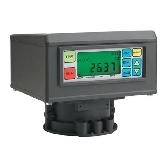
Introduction General This manual covers truck and terminal - fueling depot installation of the Veeder-Root Electronic Meter Register (EMR ) System. The EMR System consists of several major components: • Display Head (DH) - The Display Head replaces the mechanical register on a truck or a terminal - fueling depot fuel flow meter. -
Page 7: Available Parts
Introduction Available Parts Available Parts All available EMR system parts, including options, are listed below. • Display Head (P/N 84569X-XXX) - standard • Keypad Group (P/N 846000-014) - optional • Bracket with internal V-R Encoder Installation Kit (P/N 846000-015) - included with Display Head •... -
Page 8: Safety Symbols
Display Head will be installed in an application other than replacing a V-R Mechanical Meter Register, you must also have the Veeder-Root approved installation kit for that meter. The non-temperature compensation kits below (200 series), include the necessary meter connec- tion parts, a printer cable, and 35 feet of communications cable for a typical truck application. -
Page 9: Safety Warnings
Introduction Safety Warnings Safety Warnings WARNING This system operates near highly combustible fuel storage tanks. Fire or explosion resulting in serious injury or death could result if the equipment is improperly installed or modified or is used in any way other than its intended use. -
Page 10: Emr3 Truck Installation
Truck Installation Installation of the EMR System involves installing the Display Head(s), the Interconnect Box, and any optional devices (e.g., Remote Pulser, printer, etc.). Figure 1 shows an example dual Display Head installation. Control Drawing TRUCK CAB emr\tkdia3nosolvlv.eps Truck DC voltage from vehicle's accessory NON-HAZARDOUS ground circuit - at fuse block or ACC position... -
Page 11: Installation Procedures - Fuel Oil Truck Application
EMR3 Truck Installation Installation Procedures - Fuel Oil Truck Application Installation Procedures - Fuel Oil Truck Application Follow the installation procedures below for your particular EMR approved Flow Meter Installation. LIQUID CONTROLS/TOTAL CONTROL SYSTEMS FLOW METER INSTALLATION Table 1 lists the parts included in the EMR approved adaptor kit. -
Page 12: Figure 2. Remove Adjustor Dust Cover Plate
EMR3 Truck Installation Installation Procedures - Fuel Oil Truck Application emr\lc meter dust plate.eps MODE PRESET START NEXT FINISH ENTER VOLUME CURRENCY RATE SETUP Cover Remove two screws to remove dust plate cover Figure 2. Remove adjustor dust cover plate... -
Page 13: Total Control Systems Model 682 Piston Flow Meter Installation
V-R Thermowell Figure 4. Example of temperature probe installation TOTAL CONTROL SYSTEMS MODEL 682 PISTON FLOW METER INSTALLATION Table 1 lists the Veeder-Root parts needed for this installation. Table 2.- V-R Parts Required for Display Head-to-TCS 682 Piston Meter Installation Item V-R P/N Wire - Sealing 24”... -
Page 14: Figure 5. Disassembling The Tokheim Daniels, & Donovan Calibrator
EMR3 Truck Installation Installation Procedures - Fuel Oil Truck Application 2B threads) mounting holes in the base of the Display Head’s housing. You may have to rotate the Display Head right or left a little to line up the holes. Replace the mounting bolts and tighten them securely. -
Page 15: Tokheim, Daniels & Donovan Flow Meter Installation
EMR3 Truck Installation Installation Procedures - Fuel Oil Truck Application TOKHEIM, DANIELS & DONOVAN FLOW METER INSTALLATION Table 3 lists the parts included in the EMR approved kit. In addition to the “Installation Procedure” on page 6, see Figure 7 on page 11, Figure 8 on page 12, and Figure 9 on page 13 for instructions on how to disassemble then reassemble the calibrator. -
Page 16: Figure 7. Replacing The Tokheim Daniels, & Donovan Calibrator
EMR3 Truck Installation Installation Procedures - Fuel Oil Truck Application Disassemble the Tokheim calibrator and keep parts 4, 21, 22, 23, 26, and 28 (items in square blocks) emr\tok1.eps Figure 7. Disassembling the Tokheim Daniels, & Donovan calibrator... - Page 17 EMR3 Truck Installation Installation Procedures - Fuel Oil Truck Application Groove Pin (VR#510105-140)- Factory Installed in "TOP" End of Shaft Group "Top" end of shaft (VR#331431-001) 0.51" (12.96 mm) 2.615" NOTE DIFFERENCE! (66.42 mm) 0.39" ( 9.91 mm) 0.126 - 0.128" diameter through-hole (both ends) emr\tokshft.eps...
-
Page 18: Figure 8. Disassembling The Smith Meter Calibrator
EMR3 Truck Installation Installation Procedures - Fuel Oil Truck Application 0331431-001 Shaft Group 0511810-001 Truarc 011071-325 Washer Replace existing cover with 3 mounting screws and washers. Insert Truarc in "top" groove in shaft (Groove Pin is Factory Replace existing Dial installed in "Top"... -
Page 19: Smith Flow Meter Installation
EMR3 Truck Installation Installation Procedures - Fuel Oil Truck Application SMITH FLOW METER INSTALLATION Table 4 lists the parts included in the EMR approved adaptor kit. In addition to “Installation Procedure” on page 6, see Figure 10 on page 15, Figure 11 and Figure 12 on page 16, and Figure 13 on page 17 for instructions on how to disassemble then reassemble the calibrator. -
Page 20: Figure 11. Reassembling The Smith Meter Calibrator
EMR3 Truck Installation Installation Procedures - Fuel Oil Truck Application Remove cover and discard all inner parts. Keep only parts followed by an asterisk emr\smith1.ep Figure 10. Disassembling the Smith meter calibrator... - Page 21 EMR3 Truck Installation Installation Procedures - Fuel Oil Truck Application Calibrator Spring assembly If distance from face to top of calibrator support flanges = 0.850" (21.59 mm), use shaft group 331433-002; if distance = 0.635" (16.13 mm), use shaft group 331433-001 Meter dome adaptor emr/smith4.eps...
-
Page 22: Figure 12. Example Of Temperature Probe Installation In Main Case Cover
EMR3 Truck Installation Installation Procedures - Fuel Oil Truck Application Lower Group Shaft down through emr\smith3.eps bushings in cover and and in calibrator case and into bore in Smith drive gear. Shaft Group 331433-00X ("Top" end with factory installed groove pin) -
Page 23: Neptune Flow Meter Installation
EMR3 Truck Installation Neptune Flow Meter Installation Neptune Flow Meter Installation Follow the installation procedures for your particular EMR approved Flow Meter Installation. NEPTUNE FLOW METER WITH TEMPERATURE COMPENSATION Table 5.- Display Head-to-Neptune With Temp. Comp. Adaptor Kit 846000-008 Item... - Page 24 EMR3 Truck Installation Neptune Flow Meter Installation 1. Remove and put aside the four mounting bolts holding the meter register assembly to the meter adaptor mounting flange. Remove the existing mechanical register. 2. Remove the cover, P/N 86665-000, from the mechanical register’s lever arm assembly.
-
Page 25: Figure 15. Emergency Stop Switch Mounting And Wiring Diagram
EMR3 Truck Installation Neptune Flow Meter Installation 12. Get the 4” (101.60 mm) long input shaft, the 0.10” and 0.005” thick washers, the retaining ring, the groove pin, and the coupling from the installation kit. Assemble the new shaft, the 0.10” washer you removed from the Display Head shaft in the previous step, the 0.005”... -
Page 26: Emergency Stop Switch (Ess) Switch (Optional)
EMR3 Truck Installation Emergency Stop Switch (ESS) Switch (Optional) 14. Orient the encoder input shaft coupling so that it ‘mates’ with the meter adaptor input shaft, then lower the Display Head onto the meter adaptor mounting flange. 15. Rotate the Display Head on the meter adaptor mounting flange until the display is facing in the desired direction and check to see that the four meter adaptor flange mounting holes align with four of the eight tapped (1/4 - 28 UNF-2B threads) mounting holes in the base of the Display Head’s housing. -
Page 27: Wiring The Display Head
EMR3 Truck Installation Wiring the Display Head 2.76" (70) ESS bottom half w/ 2.28" yellow top removed (58) 2.76" (70) 1.67" (42.4) Push in button Pull out button to stop flow to resume flow 0.86" (4.6) mounting holes (2) 1.18"... -
Page 28: C&C Mode Switch Options
EMR3 Truck Installation C&C Mode Switch Options Encoder mounting base as shown in Figure 18. Slide the bushing into the cord grip and then screw the cord grip nut onto the cord grip and tighten securely. Attach the shield of the temperature probe cable to a grounding lug on the Pulse Encoder mounting base. -
Page 29: Figure 18. Pulse Encoder And Keypad Installations
EMR3 Truck Installation C&C Mode Switch Options Figure 18. Display head cable connections... -
Page 30: Installing Optional Keypad Kit
EMR3 Truck Installation Installing Optional Keypad Kit Corner Mounted C&C Switch Removal of corner bolt releases actuator lever of C&C switch allowing entry into C&C Mode emr\emr3ccsw.eps Figure 19. C&C mode switch configuration Installing Optional Keypad Kit Figure 20 shows the installation and wiring of the optional keypad. To attach the keypad housing mounting screws, you may have to pull/slide up the display assembly terminal block away from the Display Head. -
Page 31: Installing The Interconnection Box (Ib)
EMR3 Truck Installation Installing the Interconnection Box (IB) Chassis Ground - attached to saddle Pulse clamp and Display Head terminal 1 encoder CGND as shown Pulse encoder Route cables as mounting base shown to avoid interference with flexible shaft. Use tie wraps to... -
Page 32: Ib Power Fuse
EMR3 Truck Installation Installing the Interconnection Box (IB) 3. Run the power cable from the truck fuse block or ignition switch to the IB. Clamp the power wire at suitable intervals between the power source and the IB. Before connecting the truck power wiring, verify the following: a.Electrical system has a negative ground. -
Page 33: Figure 20. Wiring The Interconnection Box
EMR3 Truck Installation Installing the Interconnection Box (IB) 7.8" (198.12) 1.87" (47.5) 1.4" (35.56) Knockout 4" (101.6) 3.0" 0.54" (13.72) Inside (76.20) 1/2" I.P.S. Outside (5 Places) Input Ground Power GP- IN GP- OUT Input V Pulse 5V Out Voltage... - Page 34 5, 12, or 24 V for POUT-1, POUT-2, POUT-1 SP1, or SP2 are selected by Pulse Voltage Selector jumper above. See Ground “Pulse Output for EMR3” on Pulse Output DH2 page 52 for connection details. POUT-2 RS-485 B IB Network...
-
Page 35: Figure 21. Connecting 3-Way Valve To Neptune Meter - Truck Lp Gas Installations
EMR3 Truck Installation Installing the Interconnection Box (IB) Table 8.- Intrinsically Safe Wiring for IB Input Terminal Label IB-A IB-B Display Head 1 IB-A Display Head 2 IB-B (or optional Remote Dis- play) Pulse Ouput voltage jumper. Set jumper between Input V and 5, 12, or 24 V as required. -
Page 36: 3-Way Safety Valve For Truck Lp Gas Systems
EMR3 Truck Installation 3-Way Safety Valve for Truck LP Gas Systems 3-Way Safety Valve for Truck LP Gas Systems The 3-Way Safety Valve is not intended for flow control or preset control. WARNING The Three-Way Safety Valve is installed and operated in the highly combustible environment of an LPG tank. -
Page 37: Installing The 3-Way Valve
EMR3 Truck Installation 3-Way Safety Valve for Truck LP Gas Systems INSTALLING THE 3-WAY VALVE On the male pipe threads, use a pipe sealant when installing fittings or conduit to either the valve or the junction box. 1. On the valve, install a rigid metal conduit nipple in the threaded opening, provided for the solenoid wiring. Run the two red wires from the 3-way valve, through the nipple and into a metal junction box. - Page 38 EMR3 Truck Installation 3-Way Safety Valve for Truck LP Gas Systems 4. Tighten the cable bushing nuts on the cord grip to ensure a watertight seal at the cable’s entry. 5. Remove the protective closures from the 3-way valve ports.
-
Page 39: Installing The Temperature Probe (Optional)
EMR3 Truck Installation Installing the Temperature Probe (Optional) Power side terminals Ground Vehicle power J-Box Wire Nut 3-Way Valve Solenoid Wire nut White sleeve (on lead) RELAY 1 Nipple Cord Grip Wire nut Ground Suppressor diode Clamp IB Box V/R Kit P/N 846000-022 emr\3waywir.eps... -
Page 40: Temperature Probe Wire Description
Veeder-Root recommends that you purchase an off-the-shelf assembly on which to mount the printer. A suggested vendor for in-vehicle mounting hardware is Signal Measurement Corporation (SMC). You can phone them at (800) 527-1079, or write them at 12519 Wanda Lane, Magnolia, TX 77355, or contact their web site at www.smc-... -
Page 41: Figure 26. Remote Display Assembly
EMR3 Truck Installation Installing the Printer (Optional) Table 11.- Low-Cab Installation* Item SMC P/N Base plate ZPLT-1 Pillar stack PS12-A Removable platform VMI-L0 *Use Loctite® 243 Threadlocker® on all printer stand mounting bolts. (Loctite and 243 Threadlocker are registered trademarks of Loctite Corporation.) A power/data cable and three 2”... -
Page 42: Installing The Remote Display (Optional)
EMR3 Truck Installation Installing the Remote Display (Optional) Installing the Remote Display (Optional) The Remote Display consists of the items listed in Table 12: Table 12.- Remote Display Components Item Description V-R P/N Remote Display Head 84569X-X2X Remote Display Install Kit 330020-430 Opt. -
Page 43: Figure 29. Wiring Connections In Remote Pulser (Top Cover Removed)
EMR3 Truck Installation Installing the Remote Display (Optional) #30 Torx screws (4) fasten into back of Adjust mounting strips to desired Remote Display housing indents each side, then tighten nuts Mounting Strips shown in low position (2) 1 Nut and 1 lockwasher... -
Page 44: Figure 30. Example Terminal Installation With 2 Display Heads And Remote Pulser
EMR3 Truck Installation Installing the Remote Display (Optional) Figure 30. Remote display connections (rear cover removed) -
Page 45: Installing The Remote Pulser (Optional)
EMR3 Truck Installation Installing the Remote Pulser (Optional) Installing the Remote Pulser (Optional) The EMR remote pulser consists of a 5 Vdc optical encoder assembled into a stand-alone cast housing. The Remote Pulser can be mounted to either the top or the front of the meter using one of two available kits. The Remote Pulser is intended for use with a Remote Display only. - Page 46 Terminal - Fueling Depot Installation Installation of the EMR System involves installing the Display Head(s), installing the interconnect box, and installing any optional devices (e.g., remote pulser, printer, etc.). Figure 32 shows an example dual Display Head installation. Control Drawing THE FOLLOWING INFORMATION IS FOR GENERAL REFERENCE AND IS NOT INTENDED TO REPLACE RECOMMENDED NATIONAL ELECTRIC CODE (NEC) PROCEDURES.
-
Page 47: Power Conditioning Equipment Required For Terminal Installations
(these bolts will be used to attach the Display Head to the meter adaptor mounting flange). Remove the existing mechanical register. 2. If you are replacing a Veeder-Root,Liquid Controls, or TCS register go to the next step. For more information, start with “Available Parts” on page 2 and continue up to “Neptune Flow Meter Installation”. -
Page 48: Wiring The Display Head
EMR3 Terminal - Fueling Depot Installation Wiring the Display Head If you are replacing a Brodie, Brooks, or Neptune register install the necessary meter adaption kit as per direc- tions in “Neptune Flow Meter Installation” on page 18. 3. Notice the type of coupling connecting the register/preset to the meter adaptor input shaft. -
Page 49: C&C Mode Switch Options
EMR3 Terminal - Fueling Depot Installation C&C Mode Switch Options Replace the Display Head cover and screw in the four cover retaining bolts just enough to hold them in (the cover will be removed later for system calibration). C&C Mode Switch Options There are three C&C mode switch configurations:... - Page 50 EMR3 Terminal - Fueling Depot Installation Installing Optional Keypad Kit Corner Mounted C&C Switch Removal of corner bolt releases actuator lever of C&C switch allowing entry into C&C Mode emr\emr3ccsw.eps Figure 35. Optional C&C mode switch configuration Installing Optional Keypad Kit Figure 36 shows the installation and wiring of the optional keypad.
-
Page 51: Installing Optional Keypad Kit
WIRE TYPE FOR NON-BONDED METALLIC OR PVC CONDUIT Veeder-Root requires the use of shielded cable when using non-bonded metallic or PVC conduit in any portion of the wiring between the Display Head and the IB. In these installations, shielded cable must be rated less than 100... -
Page 52: Installing The Interconnection Box
EMR3 Terminal - Fueling Depot Installation Installing the Interconnection Box Use either the 4-wire cable supplied by V-R, P/N 846000-X00 or any cable or wiring with rated capacitance of less than 100 picofarads per foot (per 304.8 mm). Note that conductor wire colors vary depending on the cable manufacturer (caution: the Display Head to IB wiring illustrations in this section show wire colors in the V-R cable. - Page 53 EMR3 Terminal - Fueling Depot Installation Installing the Interconnection Box Table 13.- Power Side Wiring for IB Box Input Terminal Label Ground Input Power GP-IN Position this jumper as shown to Gen. Purpose select 5V,12V, or 24V output for GP-OUT...
- Page 54 EMR3 Terminal - Fueling Depot Installation Installing the Interconnection Box Table 14.- Intrinsically Safe Wiring for IB Input Terminal Label IB-A IB-B Display Head 1 IB-A Display Head 2 IB-B (or optional Remote Dis- play) Pulse Ouput voltage jumper. Set jumper between Input V and 5, 12, or 24 V as required.
- Page 55 EMR3 Terminal - Fueling Depot Installation Installing the Interconnection Box DC Solenoid Wiring IB Box Power side terminals J-Box Rigid conduit Wire nut White sleeve Seal off (on lead) DC Solenoid valve RELAY 1 Rigid conduit Wire nut Ground Clamp...
-
Page 56: Installing The Optional Printer
EMR3 Terminal - Fueling Depot Installation Installing the Optional Printer Installing the Optional Printer The Epson U-220A dot matrix roll printer is placed on a desk in the terminal - fueling depot office. A power/data cable is included in the printer kit. Figure 39 shows the rear panel connections to the printer. The on/off switch is on the front of the printer. -
Page 57: Rs-232 Peripheral Equipment Requirements
- baud: 9600 - parity: none - stop bits: 1 - data bits: 8 Note: for a list of serial commands, contact Veeder-Root directly. Pulse Output for EMR RANGE OF VALUES ALLOWED FOR SET PULSES/VOL • Minimum: 0.0 • Maximum: 99,999... -
Page 58: Wire Size And/Or Distance Limitations
EMR3 Terminal - Fueling Depot Installation Pulse Output for EMR3 SP1 and SP2 • SP1 and SP2 are open collector outputs with an internal pull-up resistor (2.2K) tied to Input V. The output voltage can be set to either 5, 12, or 24 volts depending on the location of the pulse voltage selector jumper wire (see Figure 40). -
Page 59: Flow Rate Limits Based On The Typical Time It Takes The Ib To Send Pulses
EMR3 Terminal - Fueling Depot Installation Pulse Output for EMR3 FLOW RATE LIMITS BASED ON THE TYPICAL TIME IT TAKES THE IB TO SEND PULSES Setting Max Flow Rate 0.1 pulse/gallon 250,000 gpm 1.0 pulse/gallon 25,000 gpm 10.0 pulses/gallon 2,500 gpm... -
Page 60: Emr3 Inhibitors - Provisions For Sealing
Inhibitors - Provisions for Sealing The EMR uses a wire with a W & M seal that prohibits tampering with the weights and measures sensitive set-up and calibration values stored in the Display Head. Once the wire seal is installed, a physical alteration to the Display Head is required to gain access to the parameters that control the metrological parameters called C&C (configuration and calibration). -
Page 61: Remote Display - Front Cover Switch
EMR3 Inhibitors - Provisions for Sealing Temperature Probe REMOTE DISPLAY - FRONT COVER SWITCH The switch is installed on the front panel of the Remote Display. The heads of the two hex head screws have been drilled through for the sealing wire. To prevent unauthorized switch activation after C&C parameters are entered and the switch is set to setup mode, the switch’s cover is replaced and sealing wire is threaded through the switch... - Page 62 EMR3 Inhibitors - Provisions for Sealing Temperature Probe Seal Sealing wire IB cover and bottom sealing wire holes emr\ibseal.eps Figure 42. IB sealing C&C Switch & Cap w/ hole for sealing wire (optional) Hex head screw (2) with hole in head...
-
Page 63: Appendix A: Emr3 Safety Instructions
Appendix A: EMR Safety Instructions 1. ATEX approved EMR systems are marked with the following information defining its limits for safe use. The product should not be installed or used in hazardous locations that are not compatible with the following: EEx ia II A T4 Ui: 13.365 Vdc Ii: 687 mA... - Page 64 E C D e c l a r a t i o n o f C o n f o r m i t y f o r E M R 3 I s s u e d b y : V e e d e r - R o o t E n v i r o n m e n t a l S y s t e m s , H y d r e x H o u s e , G a r d e n R o a d ,...
- Page 65 M a n u f a c t u r e r V e e d e r - R o o t C o . 1 2 5 P o w d e r F o r e s t D r i v e P o s t O f f i c e B o x 2 0 0 3 S i m s b u r y , C T 0 6 0 7 0 U S A...
- Page 66 Appendix B - Remote Display Front Panel C&C Switch Drilling Template Scale: Full...
- Page 68 For technical support, sales or other assistance, please visit: www.veeder.com...
Need help?
Do you have a question about the EMR3 and is the answer not in the manual?
Questions and answers
Is the interconnecting box available
Yes, the Veeder-Root EMR3 Interconnect Box with Installation Kit is available for purchase.
This answer is automatically generated