Table of Contents
Advertisement
Introduction
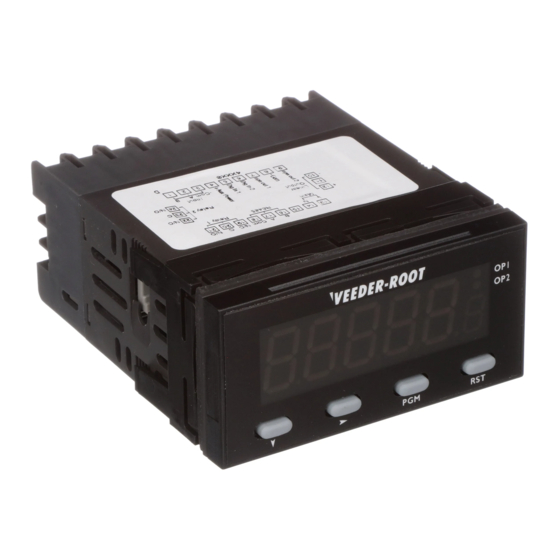
Your Veeder-Root brand C628 Rate Meter with Total is one model in a family of 1/8 DIN
units which offers breakthrough display technology as well as easy-to-program single-line
parameters. Designed to provide instant visual feedback regarding an application's key
input value, the C628 not only has a 0.71" high LED display (27% larger than other 1/8
DIN units), but also the ability to change display color based on process status
(programmable parameter in Operation Mode). Easy programming is made possible via a
help function and a secondary legend display.
This manual will guide you through the installation and wiring of your C628 unit with
information on proper panel mounting and rear terminal layout and wiring instructions.
In addition, the instrument's operation and programming modes are thoroughly
explained. The Operation Mode provides day to day operation and allows editing of
preset values. The Program Mode enables the configuration of various parameters prior
to initial operation. These parameters include those for basic configuration as well as
other settable features which will enhance the functionality and usability of the device.
This manual also provides
information on the C628 Rate
Meter with Total's alarms;
transistor, relay and linear
outputs; product
specifications; and ordering
and warranty procedures.
Features
• AWESOME 0.71" high digit LED display
• Programmable color change display based on
an event
• Programmable help function and secondary
legend display
• Display configurable for update time, min.
number of pulses, and forced zero time
• Optional linear output relative to rate
• Choice of NPN, PNP, or magnetic primary
input
• Filter speed settable for 20, 200, or 10,000 Hz
• Standard outputs: two NPN transistors & one
relay (optional 2nd relay)
• Front panel reset enable and alarm lockout
• Optional RS-485 plug in card
• CE approved
www.TheTimerAndCounterCompany.com
Index
Technical Manual
702138-0004
Veeder-Root
Series C628
Rate Meter
with Total
page 2
page 3
(C628-5XXX)
page 4
page 5
page 6-10
page 11
page 12
page 12
brand
Advertisement
Table of Contents

Related Manuals for Veeder-Root Series C628


Summary of Contents for Veeder-Root Series C628
-
Page 1: Table Of Contents
Introduction Your Veeder-Root brand C628 Rate Meter with Total is one model in a family of 1/8 DIN units which offers breakthrough display technology as well as easy-to-program single-line parameters. Designed to provide instant visual feedback regarding an application’s key input value, the C628 not only has a 0.71”... -
Page 2: Installation
I N S T A L L A T I O N PANEL MOUNTING 100mm VEEDER-ROOT 82344 48mm 96mm 10mm 92mm +0.5 -0.0 PANEL 45mm CUTOUT +0.5 -0.0 SIZE The instrument can be mounted in a panel with a thickness of up to 6mm. The... -
Page 3: Wiring
www.TheTimerAndCounterCompany.com I N S T A L L A T I O N WIRING REAR TERMINAL CONNECTIONS Power Supply RS-485 Comm. Relay 1 + VDC - (opt.) 14 15 Linear Relay 2 Output (opt.) (opt.) Input Power For an AC powered unit, Terminal #13 serves as the line or Hot side connection for AC powered units and as the positive side for DC powered units. -
Page 4: Operation
O P E R A T I O N FRONT PANEL Primary Display VEEDER-ROOT Output Indicators 82345 Secondary Display Down Key Scroll Key Program Key Reset Key Key Functions Display Functions Function Display Function Down In Operation Mode: Used in edit operation to decrement Primary In Operation Mode: Default display is the rate value. -
Page 5: Operation Mode
O P E R A T I O N OPERATION MODE CHANGING A PARAMETER VALUE Default display is the rate value. VEEDER-ROOT Use the Scroll Key to move from left to VEEDER-ROOT 34567 23456 right and highlight the digit that needs to be changed. -
Page 6: Programming
P R O G R A M M I N G PROGRAM MODE ENTERING PROGRAM MODE AND BASIC OPERATION The Program Mode can be accessed from the VEEDER-ROOT 23456 Operation Mode by holding the Program Key for 3 seconds. for 3 seconds... - Page 7 www.TheTimerAndCounterCompany.com P R O G R A M M I N G PROGRAM MODE Continued Rate Calibration Factor Decimal Point rCALP Function: Sets the decimal point position for the rate calibration factor display Adjustment Range: 0 to 0.0000 Default Value: 0 Rate Calibration Factor r C A L Function: Used to scale the input into engineering units by multiplying this value by the input frequency...
- Page 8 www.TheTimerAndCounterCompany.com P R O G R A M M I N G PROGRAM MODE Continued Filter Speed S P E E d Function: Enables the debounce filter of the meter to properly match the application Adjustment Range: 2 0 0 1 0 0 0 0 200: The unit will accept up to 20: The unit will accept up to 20...
- Page 9 www.TheTimerAndCounterCompany.com P R O G R A M M I N G PROGRAM MODE Continued Front Panel Reset Enable Function: Determines whether the Front Panel Reset key can be used to reset the rate value Adjustment Range: d i S Enable: The rate value can be reset Disabled: The Front Panel Reset Key is while being viewed in Operation Mode by...
-
Page 10: Program Mode
www.TheTimerAndCounterCompany.com P R O G R A M M I N G PROGRAM MODE Continued Communication Address (Appears only if communication board is installed and activated) A d d r Function: Defines the unique communication address of the counter Adjustment Range: 1 to 99 Default Value: 1 Baud Rate (Appears only if communication board is installed and activated) b A u d... -
Page 11: Appendix A Specifications
www.TheTimerAndCounterCompany.com A P P E N D I X SPECIFICATIONS Count Inputs Communication Type: Sinking/Sourcing or Contact Closure Type: Serial asynchronous, UART to UART Frequency: 10 kHz max. Data Format: Open ASCII: One start bit, even parity seven Logic: Low < 2.0 VDC, High > 3.0, 30V max. data bits, one stop bit Impedance: 10 KΩ... -
Page 12: General
www.TheTimerAndCounterCompany.com G E N E R A L ORDERING INFORMATION C628 - 5 2nd Relay Option Power Supply 0 None 0 90-264 VAC 1 2nd Relay 2 20-50 VAC/VDC Serial Communication Linear Output Option Option 0 None 0 None 5 RS-485 3 Linear Output Additional outputs and options can be field installed through plug-in boards...
Need help?
Do you have a question about the Series C628 and is the answer not in the manual?
Questions and answers