Table of Contents
Advertisement
Quick Links
Danaher Specialty Products
1-800-390-6405
www.danaherspecialtyproducts.com/Veeder-Root
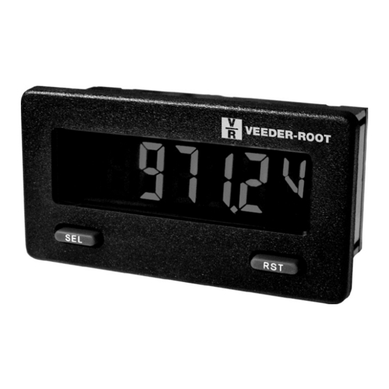
MODEL RFMP - MINIATURE ELECTRONIC 5-DIGIT PROCESS METER
U L
C
US LISTED
R
IND. CONT. EQ.
51EB
GENERAL DESCRIPTION
The FLEX MINI Series provides the user the ultimate in flexibility, from its
complete user programming to the optional setpoint control and communication
capability. The FLEX MINI accepts a DC voltage or current input signal and
provides a display in the desired unit of measure. The meter also features
minimum and maximum display capture, display offset, units indicator, and
programmable user input. The display can be toggled either manually or
automatically between the selected displays.
The FLEX MINI display has 0.48" (12.2 mm) high digits. The LCD is
available in two versions, reflective or red/green backlight. The backlight
version is user selectable for the desired color and also has variable display
intensity.
The capability of the FLEX MINI can be easily expanded with the addition
of option cards. The setpoint output cards are field installable with programmable
setpoints. Serial communications capability for RS232 or RS485 can be added
with a serial option card.
The FLEX MINI can be powered from an optional Veeder Root Micro-Line/
Sensor Power Supply (MLPS), which attaches directly to the back of a FLEX
MINI. The MLPS is powered from 85 to 250 VAC and provides up to 400 mA
to drive the unit and sensors.
INPUT
The FLEX MINI is a DC Process meter. It features voltage and current input
ranges, that are selected by the user via a programming jumper and software
input range selection. The ranges consist of the following: 0 to 10 V, 0(4) to 20
mA, or 0 to 50 mA. Users should select the appropriate voltage range that
DIMENSIONS In inches (mm)
SEL
Note: Recommended minimum clearance (behind the panel) for mounting clip installation is 2.15" (54.6) H x 3.00" (76.2) W.
1.54 (39.1)
RST
2.95 (74.9)
.15 (3.8)
THREE SELECTABLE D.C. RANGES
0 to 10 V, 0(4) to 20 mA, 0 to 50 mA
MINIMUM AND MAXIMUM DISPLAY CAPTURE
LCD, REFLECTIVE OR RED/GREEN LED BACKLIGHTING
0.48" (12.2 mm) HIGH DIGITS
OPTIONAL SETPOINT OUTPUT CARD
OPTIONAL SERIAL COMMUNICATION CARD (RS232 or RS485)
OPTIONAL USB PROGRAMMING CARD
OPERATES FROM 9 TO 28 VDC POWER SOURCE
FRONT PANEL PROGRAMMABLE
DISPLAY COLOR CHANGE CAPABILITY AT SETPOINT OUTPUT
NEMA 4X/IP65 SEALED FRONT BEZEL
covers their maximum input.
SAFETY SUMMARY
All safety related regulations, local codes and instructions that appear in this
literature or on equipment must be observed to ensure personal safety and to
prevent damage to either the instrument or equipment connected to it. If
equipment is used in a manner not specified by the manufacturer, the protection
provided by the equipment may be impaired.
Do not use this meter to directly command motors, valves, or other actuators
not equipped with safeguards. To do so can be potentially harmful to persons or
equipment in the event of a fault to the meter.
CAUTION: Risk of Danger.
Read complete instructions prior to
installationand operation of the unit.
.13 (3.3)
1.29 (32.8)
1.71
(43.4)
1
Bulletin No. RFMO-G
Drawing No. LP0655
Released 12/12
CAUTION: Risk of electric shock.
+.024
1.30
-.000
+6
(33
-0
+.025
2.68
-.000
+8
(68
)
-0
)
Advertisement
Table of Contents

Related Manuals for Veeder-Root RFMP Series


Summary of Contents for Veeder-Root RFMP Series
- Page 1 Drawing No. LP0655 Released 12/12 Danaher Specialty Products 1-800-390-6405 www.danaherspecialtyproducts.com/Veeder-Root MODEL RFMP - MINIATURE ELECTRONIC 5-DIGIT PROCESS METER THREE SELECTABLE D.C. RANGES 0 to 10 V, 0(4) to 20 mA, 0 to 50 mA MINIMUM AND MAXIMUM DISPLAY CAPTURE ...
-
Page 2: Specifications
rderinG nforMation TYPE MODEL NO. DESCRIPTION PART NUMBER Process Meter with Reflective Display RFMP00R FLEX MINI FLEX MINI Process Meter with Backlight Display RFMP00 FLEX MINI Single Relay Option Card RFMRL00 FLEX MINI Dual Sinking Open Collector Output Card RFMSK00 Optional Plug-in Cards RS485 Serial Communications Card RFMCOMM... -
Page 3: Installation Environment
ptional ardS ADDING OPTION CARDS The FLEX MINI meters can be fitted with optional output cards and/or serial communications cards. The details for the plug-in cards can be reviewed in the specification section below. The plug-in cards, that are sold separately, can be : 30 VDC installed initially or at a later date. -
Page 4: W Iring The M Eter
3.0 i nStallinG ardS The Plug-in cards are separately purchased option cards that perform specific CAUTION: The Plug-in cards and main circuit board contain static functions. The cards plug into the main circuit board of the meter sensitive components. Before handling the cards, discharge static charges from your body by touching a grounded bare metal object. -
Page 5: Input Wiring
4.3 INPUT WIRING 2 Wire With External Power CAUTION: Power input common is NOT isolated from user and input commons. In order to preserve the safety of the meter application, the power input common must be suitably isolated from hazardous live 2 WIRE TRANSMITTER earth referenced voltage;... -
Page 6: Programming Menu
5.0 r evieWinG the ront uttonS and iSplay BUTTON DISPLAY MODE OPERATION ENTERING PROGRAM MODE PROGRAMMING MODE OPERATION Index display through enabled values Press and hold for 2 seconds to activate Store selected parameter and index to next parameter Advances through the program menu Resets values (MIN/MAX) or outputs Increments selected parameter value or selection OPERATING MODE DISPLAY DESIGNATORS... -
Page 7: Parameter Menu
6.1 Module 1 - S iGnal nput araMeterS 1-INP PARAMETER MENU 1-INP rANGE dECPt OFSEt FILtr bANd StYLE INP 1 dSP 1 INP 2 dSP 2 USrIN U-ASN Input Value Display Value Input Value Input Display Display Filter Filter Scaling Display Value User Input User Input... - Page 8 USER INPUT FUNCTION DISPLAY MODE DESCRIPTION Serial transmit of the active parameters USrIN Print Request selected in the Print Options menu Print (Module 5). Same as Print Request followed by a Print and Reset P-r5t momentary reset of the assigned value(s). DISPLAY MODE DESCRIPTION...
- Page 9 6.3 Module 3 - d iSplay and ront anel utton araMeterS 3-dSP PARAMETER MENU 3-dSP Backlight Unit Only dSP-t ZErO ScroL UNItS COLOr d-LEV CodE Display Front Panel Front Panel Zero Display Display Units Display Display Programming Update Time Display Reset Enable Scroll Indicator...
- Page 10 6.4 Module 4 - S etpoint utput araMeterS 4-SPt PARAMETER MENU 4-SPt Backlight Unit Only SPSEL Act-n SPt-n HYS-n tON-n tOF-n rSt-n rEn-n Stb-n ChC-n Setpoint Setpoint Setpoint Hysteresis On Time Off Time Output Reset Output Reset Standby Change Display Select Action Value...
- Page 11 OUTPUT RESET WITH DISPLAY RESET button or user input manual reset, serial reset command or meter power cycle. When the user input or button is activated (momentary action), rEn-n the corresponding “on” output is reset immediately and remains off until the trigger point is crossed again.
- Page 12 rfMp proGraMMinG QuicK overvieW...
Need help?
Do you have a question about the RFMP Series and is the answer not in the manual?
Questions and answers