Veeder-Root EMR3 Setup And Operation Manual
Hide thumbs
Also See for EMR3:
- Installation manual (68 pages) ,
- Installation instructions manual (14 pages) ,
- Troubleshooting manual (13 pages)
Table of Contents
Advertisement
Advertisement
Table of Contents

Subscribe to Our Youtube Channel
Related Manuals for Veeder-Root EMR3


Summary of Contents for Veeder-Root EMR3
- Page 1 ● Manual No: 577013-766 Revision: I Setup and Operation Manual...
- Page 2 Notice Veeder-Root makes no warranty of any kind with regard to this publication, including, but not limited to, the implied warranties of merchantability and fitness for a particular purpose. Veeder-Root shall not be liable for errors contained herein or for incidental or consequential damages in connection with the furnishing, performance, or use of this publication.
-
Page 3: Table Of Contents
Display Button Functions - Optional Keypad ..............7 Data Entry Navigation Buttons ......................8 Data Entry with Standard Keypad ..................8 Data Entry with Optional Keypad ..................9 EMR3 Operating States and Modes System Operating States ....................10 Pre-Dispense State .....................10 Dispense State......................10 Finish State .........................10 System Operating Modes ....................10... - Page 4 Dispensing Currency with Price Code Before & Currency Preset After Dispensing ...51 Dispensing Currency with Price Code and Volume Preset Before Dispensing...52 Dispensing Currency with Price Code & Volume Preset After Dispensing ....52 Dispensing With Tank ID Enabled ................52 EMR3 Troubleshooting Guide Testing an EMR³ System ....................54 Display Head.......................54 Lcd Display........................54 Pulse Generator Input Check..................54...
- Page 5 E65 - Calibration Error ....................58 Other Problems .......................58 System Boots Up Okay, but Display Keys Don’t Respond .........58 Appendix A: EMR3 Setup - Programming Tips For Typical Single or Dual-head Installations with One IB ..........A-1 Appendix B: Epson Printer Characters ............
- Page 6 Table of Contents Figure 21. Shift Report Format .................23 Figure 22. Date Format Setup ..................23 Figure 23. Date/Time Setup ..................24 Figure 24. System Address Setup ................24 Figure 25. IB Address Setup ..................25 Figure 26. Port 1 Assign Setup .................25 Figure 27. Port 2 Assign Setup .................26 Figure 28.
-
Page 7: System Options
Introduction This manual describes setup and operating procedures for the EMR Electronic Meter Register System. This manual assumes that the Display Head, Interconnection Box, and printer are installed and connected. System Options There are three options available for the EMR System: •... -
Page 8: Related Manuals
Setup and Operation Manual Related Manuals Entering the C&C Mode requires that a seal-protected wire jumper or switch in the Display Head be changed. Changes in this mode must be accordance with local W&M authority requirements. In the C&C Mode you: •... -
Page 9: Safety Warnings
Setup and Operation Manual Safety Warnings Safety Warnings WARNING This system operates near highly combustible fuel storage tanks. Fire or explosion resulting in serious injury or death could result if the equipment is improperly installed or modified or is used in any way other than its intended use. -
Page 10: Display Head
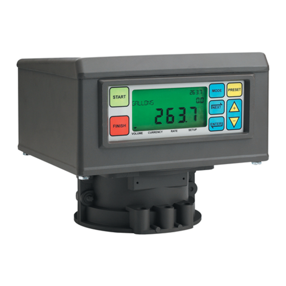
Setup and Operation Manual Display Head Display Head The EMR Display Head display features are shown in Figure 1 and Figure 2. Grand Totalizer Field Preset Indicator Operating Icons Preset Field MODE PRESET START Descriptor Field VEEDER ROOT CO NEXT Register Field FINISH ENTER... -
Page 11: Boot-Up Test Sequence
Setup and Operation Manual Boot-Up Test Sequence Boot-Up Test Sequence When power is initiated to the Display Head, the screen will power up with a test sequence that satisfies the requirements of the local Weights and Measures authority. The Display Head test sequence follows below: •... -
Page 12: Activating The Display
Setup and Operation Manual Activating the Display • Subsequently, if no button press or operation occurs in 30 seconds, the display will go blank and wait for a button to be pressed to reactivate. Initially, when reactivated, the Display Head enters the Volume mode. Once the unit has been setup, the default reactivation mode will be the Pre-Dispense mode you choose in setup. -
Page 13: Display Button Functions - Standard Keypad
Setup and Operation Manual Display Button Functions - Standard Keypad • Printer - A page icon will display only when a printer is configured for the system. A slow flashing page icon is displayed when the printer is actively printing. A fast flashing page icon is displayed when the printer requires operator attention. -
Page 14: Data Entry
Data Entry Navigation Buttons The navigation buttons consist of the MODE, NEXT, ENTER, PRESET, and +/- buttons. They can be used to either select and set parameters, or select and set alpha and numeric values. • MODE - Press to navigate through the Modes; Setup, Volume, Currency, and Rate. •... -
Page 15: Data Entry With Optional Keypad
Setup and Operation Manual Data Entry with Optional Keypad Data Entry with Optional Keypad Upon entering the Descriptor or Preset Field with the use of the navigation buttons the optional keypad will permit alpha and numeric entries. To enter a numeric in the Preset Field just select the appropriate button on the optional keypad. When a selection is made, the curser will automatically sequence to the position to the right. -
Page 16: Emr3 Operating States And Modes
Operating States and Modes System Operating States The system has three operating states, Pre-Dispense, Dispense, and Finish. PRE-DISPENSE STATE Prior to pressing the START button, the system is in the Pre-Dispense state. The setting of system parameters, pricing, and tax codes for a delivery are made in this state. DISPENSE STATE After pressing the START button (and selecting a product if setup for multiple products), the system enters the Dispense state. -
Page 17: Setup Mode
Setup and Operation Manual System Operating Modes SETUP MODE The user can access the Setup Mode before a delivery to change a variety of parameters that are not required to be under weights & measure seal. Once the delivery state is active, the Setup Mode cannot be accessed. The Setup Mode is used to enter price codes, default mode setting, single flow and fast flow knock-off values and other non-metrological settings. -
Page 18: Setup Mode
Setup Mode Initiating the Setup Mode 1. Turn On power to the Display Head and wait until the boot-up sequence completes. 2. Depress the MODE button until the indicator at the bottom of the display points to Setup. 3. On initial power-up of the Display Head, the first Setup Mode category, PRICING, displays in the Descriptor Field. -
Page 19: Enter Security Code
Setup and Operation Manual Setup Mode Categories ENTER SECURITY CODE Figure 6 illustrates the initial logging in procedure using the default Passcode after Security Codes are enabled in C&C Mode (see Figure 51). Figure 7 shows the procedure for logging in using an assigned Passcode, and Figure 8 shows how to log out. -
Page 20: Pricing
Setup and Operation Manual Setup Mode Categories PRICING Figure 9 illustrates Pricing setup in Setup Mode. ENTER ENTER Press up/down PRICE CODE 1 PRICING NEXT NEXT to change digit CHANGE PRICE X NEXT PRICE X ENTER Press to accept and NEXT to ASSIGN TAX/DIS choice move to next digit. -
Page 21: Defaults
Setup and Operation Manual Setup Mode Categories DEFAULTS Figure 11 illustrates Defaults setup in Setup Mode. ENTER See Start Modes and START MODES DEFAULTS NEXT Presets figures that PRESETS follow for these setups. Press the up/down buttons to cycle through remaining Setup Mode categories RELAY CONTROL SECURITY... -
Page 22: Relay Control
Setup and Operation Manual Setup Mode Categories Presets Figure 13 illustrates Presets setup in Setup Mode. Press ENTER ENTER ENTER to return to ENTER DEFAULTS VOLUME MODE PRESET ENABLE NEXT NEXT PRESETS CURRENCY MODE PRESET DISABLE Make your changes to the preset, pressing Press ENTER up/down arrows to PRESET 1... -
Page 23: Security
Setup and Operation Manual Setup Mode Categories SECURITY Figure 15 illustrates the procedure for setting user Passcodes and user access to certain setup parameters. ENTER ENTER NEXT NEXT SECURITY USER 1 CHANGE CODE USER 2 CHANGE ASSIGNMENTS USER 3 Note: Authorization to change pass codes and assignments is determined by Press the up/down how you are logged in to the system (see Entering Security - Logging In). -
Page 24: Printer Option
Setup and Operation Manual Setup Mode Categories PRINTER OPTION Figure 16 illustrates Printer Option setup in Setup Mode. ENTER ENTER ENTER SLIP PRINTER PRINTER OPTION ENABLE PRINTER ADVANCE NEXT NEXT NEXT ROLL PRINTER DISABLE PRINTR PRINT TEST PAGE Printer type assigned to this port must agree Press the up/down with the printer type selected in Printer Option setup. -
Page 25: Figure 17. Delivery Ticket Format
Setup and Operation Manual Setup Mode Categories *********************************** Veeder-Root Co. Header EMR-3 (Up to 4 lines) *********************************** Optional START MMM-DD-YYYY HH:MM:SS FINISH MMM-DD-YYYY HH:MM:SS Date/time TICKET NUMBER 50399 PROD DSCRPT X PROPANE METER ID GENERIC 12345 TANK ID TANK DEFAULT... -
Page 26: View Records
Setup and Operation Manual Setup Mode Categories VIEW RECORDS Figure 18 illustrates View Records setup in Setup Mode. ENTER RECORD 1 VIEW RECORDS VIEW LINES PRINT RECORD RECORD 50 Note: View each line or print Note: Up to the last 50 transaction records the selected report. -
Page 27: Restore Records
Setup and Operation Manual Setup Mode Categories RESTORE RECORDS Figure 19 illustrates Restore Records procedure in Setup Mode. RESTORE RECORDS ENTER DECLINE ACCEPT RESTORING TRANSCTION 50, 49, ... 1 Note: Last 50 Transactions are being Press the up/down restored. Counts down from 50 to 1 buttons to cycle (number of stored transactions may through remaining... -
Page 28: Figure 20. Shift And Shift Report Setup
Setup and Operation Manual Setup Mode Categories Press ENTER to accept any changes and/or ENTER continue pressing to return to SHIFT START TIME : HH:MM ACCEPT : HH:MM ENTER NEXT NEXT NEXT SHIFT SHIFT TIME END TIME : HH:MM DECLINE : HH:MM ODOMETER TANK LOAD PRINT REPORT... -
Page 29: Date Format
Setup and Operation Manual Setup Mode Categories Report Line Item Source SHIFT BEGIN: Starting time/date of the shift SHIFT END: Ending time/date of the shift (only displayed if shift has ended ) ODOMETER START: Odometer reading entered at the start of the shift ODOMETER END: Odometer reading entered at the end of the shift MILES DRIVEN:... -
Page 30: Time/Date
Setup and Operation Manual Setup Mode Categories TIME/DATE Figure 23 illustrates Time/Date setup in Setup Mode. Press up/down arrows to scroll through the choices, and NEXT to move from one MMM DD HH:MM:SS YYYY group of the date, time, or year to another. -
Page 31: Figure
IB ADDRESS. SET IB ADDRESS 16 *IB NETWORK ADDRESS Note: an IB's Port 1 and 2 network addresses are automatically assigned by the EMR3 System and are shown in the table below for reference only. IB ADDRESS LOCAL PORT 1 LOCAL PORT 2 Figure 25. -
Page 32: Figure
Epson model TM-295 (V-R Kit #846000-020). Slip printer is the standard printer. OBC selection configures the port for RS-232 serial communication between the EMR system and an onboard computer. Consult Veeder-Root for required communication protocol. This is the default PORT 2 assignment. -
Page 33: Figure
Setup and Operation Manual Setup Mode Categories Printer Address Figure 29 illustrates Printer Address setup choices. Press ENTER to return ENTER to SYSTEM ADDRESS Press ENTER to accept PRINTER ADDRESS LOCAL PRINTER 1 NEXT ENTER choice and return to LOCAL PRINTER 2 PRINTER ADDRESS. -
Page 34: Time Delays
Setup and Operation Manual Setup Mode Categories TIME DELAYS Figure 30 illustrates Time Delay setup in Setup Mode. ENTER Press the up/down arrows to scroll through the numbers, and NEXT NEXT NEXT ENTER TIME DELAYS BACKLIGHT SET SECONDS to move from one BLANK SCREEN number to the next. -
Page 35: C&C Mode
C&C Mode Initiating the C&C Mode NOTE: You must first configure the display head for access to C&C Mode as instructed in the EMR Installation Guide (V-R P/N 577013-758). 1. Press MODE button until the indicator at the bottom of the display points to SETUP. 2. -
Page 36: Language
Setup and Operation Manual C&C Mode Setup Categories LANGUAGE Figure 32 illustrates Language setup in C&C Mode. Press ENTER to accept any changes and/or continue pressing to return to LANGUAGE ENTER LANGUAGE NEXT NEXT LABEL CHANGES NEXT Go to Printer Labels Setup (Next page) PRINTER LABELS ENGLISH VOLUME LABELS... -
Page 37: Figure
TOTAL TAX/DISCOUNT 2 TOTAL TAX/DISCOUNT 3 TOTAL TAX/DISCOUNT 4 TOTAL TAX/DISCOUNT 5 TOTAL TAX/DISCOUNT 6 Veeder-Root Co. Note: Any or all of these four lines EMR-3 can be used for the header at the "blank" top of the printed ticket. -
Page 38: Display Syntax
Setup and Operation Manual C&C Mode Setup Categories DISPLAY SYNTAX Figure 34 illustrates Display Syntax setup in C&C Mode. Table 1 shows the EMR display syntax defaults. ENTER ENTER Press ENTER to accept DECIMAL SYMBOL 8888.88 ENTER SELECT DEC SYM NEXT NEXT choice... -
Page 39: Temperature
Setup and Operation Manual C&C Mode Setup Categories TEMPERATURE Figure 35 illustrates Temperature Probe’s setup in C&C Mode. Press ENTER to accept any changes in any column - and/or continue pressing to return to TEMPERATURE ENTER GO TO TEMPERATURE TEMPERATURE NEXT CELSIUS NEXT... -
Page 40: Fuel Source
Setup and Operation Manual C&C Mode Setup Categories FUEL SOURCE Figure 37 illustrates Fuel Source setup in C&C Mode. If you are going to make temperature compensated deliveries, before performing Fuel Source setup, you must select either coefficient (of expansion) or density as the temperature compensation method in Delivery Options setup (see Figure 47). -
Page 41: Figure
Quadrature is the default. have to reset this entry to the opposite direction. Note: Select Quadrature for the standard Veeder-Root Pulse Generator. The Quadrature input type is the only input type available in this version of software. Figure 39. Input Type Setup Product Description Figure 40 illustrates Product Description setup choices. -
Page 42: Figure
Setup and Operation Manual C&C Mode Setup Categories Press ENTER to return ENTER to FUEL SOURCE Up to 8 Products Can be Assigned TEMPERATURE COMPENSATION* PROD DSCRPT 1 CAL NUMBER PRODUCT DSCRIP NEXT NEXT PRODUCT TYPE PRODUCT NAME PROD DSCRPT 8 *Note: Coefficient or Density will display depending on choice made in Delivery Options setup (existing) -
Page 43: Figure
Setup and Operation Manual C&C Mode Setup Categories Table 2 - Product Temperature/Coefficient of Expansion Defaults Product Coefficient °C Coefficient °F Default Density at 15°C OIML R63 Table Gasoline 0.00126 0.00070 737 kg/m Diesel 0.00081 0.00045 849 kg/m Kerosene 0.00090 0.00050 820 kg/m Aviation gas... - Page 44 Setup and Operation Manual C&C Mode Setup Categories Table 4 - Minimum & Maximum Product Densities at 15°C Min. Density Max. Density Default Density OIML R63 Product (kg/m (kg/m (kg/m Table Gasoline 600.0 770.0 737.0 Diesel 838.6 1200.0 849.0 Kerosene 787.6 838.5 820.0...
-
Page 45: Meter Calibration
Setup and Operation Manual C&C Mode Setup Categories Table 5 - 12 Temperature/Density Pairs Propane Density (Default) Butane Density (Reference) Entry No. Temp (°C) Temp (°F) (kg/m (kg/m 522.0 594.0 15.0 510.0 585.0 23.9 496.0 574.0 29.4 487.0 568.0 35.0 478.0 562.0 40.6... -
Page 46: Figure
For example, the first rate you dispense product at a very slow rate, but for each of the additional calibration rates you increase the flow. Once calibration is complete, the EMR3 will calculate the amount of product dispensed based on interpolation. Press ENTER to accept... -
Page 47: Figure
Setup and Operation Manual C&C Mode Setup Categories Manual Calibration Figure 44 illustrates meter Manual Calibration (multipoint) setup procedure. This method requires the manufacturer’s meter error chart. Repeat this procedure until Press ENTER to ENTER return to you have entered a corrected ENTER ENTER encoder count from the table... -
Page 48: Configure I/O
Setup and Operation Manual C&C Mode Setup Categories CONFIGURE I/O Figure 45 illustrates Configure I/O setup in C&C Mode. ENTER Press to accept ENTER DISABLE CONFIGURE I/O NEXT NEXT EMERGENCY STOP entry and/or ENABLE REM START/STOP back up one step. PULSE OUTPUT NOTES: REMOTE DISPLAY... -
Page 49: Delivery Options
Setup and Operation Manual C&C Mode Setup Categories DELIVERY OPTIONS Figure 47 illustrates Delivery Options setup in C&C Mode. This option lets you enable or disable price changing within the Delivery State as per your regulatory requirements. In this setup you also select coefficient (of expansion) or density as the temperature compensation method for deliveries, enable delivery timeout, and enable tank ID input. -
Page 50: Figure
Line 1 Line 1 END OF REPORT END OF REPORT CONFIGURE I/O Top of ticket Line 2 Top of Report Line 2 Veeder-Root Co. ************************** OEM MESSAGE Line 3 Line 3 EMR-3 Veeder-Root Co. DELIVERY OPTIONS Line 4 Line 4... -
Page 51: Restart
You want to modify the example Delivery them around. Line 1 END OF REPORT Line 2 Veeder-Root Co. Ticket format as follows: Line 3 EMR-3 • Move TICKET NUMBER from line 10 to 15 1. Copy METER ID line 13 to line 38. -
Page 52: Security Code
Setup and Operation Manual Exiting C&C Mode SECURITY CODE Figure 51 illustrates the Security Code enabling procedure in C&C Mode. Enables the security code feature. In Setup Mode, select ENTER NEXT SECURITY CODE ENABLE the Enter Security Code setup CLEAR SECURITY CODE to enter the actual security DISABLE code and assignments. -
Page 53: Operation Of The System
Operation of the System Multiple Products The EMR is capable of delivering multiple products through the same meter. If more than one product is set up in the setup menu, when the START button is depressed, the multiple product selection is initiated and the first product is displayed. -
Page 54: Entry Of Price Codes & Tax/Discount Assignment In Setup Mode
Setup and Operation Manual Entry of Price Codes & Tax/Discount Assignment in Setup Mode In the Currency Mode the system defaults to the price prompt. At the price screen the price is displayed in its net value in the Preset Field. The selection of a new price is accomplished by simply pressing the NEXT button. The price, whether it is the default price previously entered, is displayed in the change price screen with its base value in the preset field and its net value in the register field. -
Page 55: Temperature Compensation Delivery Feature
Setup and Operation Manual Temperature Compensation Delivery Feature Temperature Compensation Delivery Feature After pressing FINISH following a Temperature Compensated delivery, the operator can toggle the display between Net Delivered Volume and Gross Delivered Volume by pressing the +/- button. This action toggles the delivered volume on the display only. -
Page 56: Typical Dispensing Examples
Setup and Operation Manual Typical Dispensing Examples Typical Dispensing Examples The following scenarios outline the steps the operator may take to dispense product. The two basic methods of delivery are Volume and Currency. They are introduced into the default mode selected in setup for pre-dispense. The operator selects the options appropriate for that mode and presses start to begin the actual dispensing. -
Page 57: Dispensing Currency With Price Code Before Delivery But Without Preset
Setup and Operation Manual Typical Dispensing Examples DISPENSING CURRENCY WITH PRICE CODE BEFORE DELIVERY BUT WITHOUT PRESET The following steps the operator may take to dispense product with price but without a preset. 1. In Currency Mode, press NEXT button to display Change Price screen. 2. -
Page 58: Dispensing Currency With Price Code And Volume Preset Before Dispensing
Setup and Operation Manual Typical Dispensing Examples DISPENSING CURRENCY WITH PRICE CODE AND VOLUME PRESET BEFORE DISPENSING 1. In Currency Mode, press NEXT button to display Change Price screen. 2. Press +/- button to scroll to the desired price code and press ENTER Button. The net price is displayed.(If the user wishes to alter the price while retaining the associated tax code they press NEXT again to Enter Price screen. - Page 59 Setup and Operation Manual Typical Dispensing Examples For multiple deliveries when you make the first dispense, you can enter a new TANK DEFAULT label prior to the second dispense. This new label will then appear before the third dispense, forth, etc. until the FINISH button is pressed.
-
Page 60: Emr3 Troubleshooting Guide
Troubleshooting Guide Most errors are the result of poor terminations of wiring, either in a junction box, or at the terminal strips in the IB box or Display Head. Testing an EMR³ System DISPLAY HEAD To perform a Display Head Complete Self-Diagnostic Check, cycle power to the EMR³ system. To cycle power, turn the power off for at least 20 seconds before turning it on again. -
Page 61: No Price Entry
Before replacing the encoder check the IB input voltage for dropout or power surges. Some solenoid valves do not have diode suppression and may cause the supply voltage to drop out. Add diodes (Veeder-Root P/N 846000-022) across the solenoid coils as noted in the installation manual. An over speed condition (>1250 rpm) will also cause an E04 error. -
Page 62: E15 - Ram Fail
Setup and Operation Manual System Error Codes E15 - RAM FAIL Test of static random access memory. The RAM is a piece of semiconductor memory hardware used as a temporary data storage device. To either write or read data into RAM the CPU (central processing unit) places address and data on the bus lines and then toggles the appropriate control signals. -
Page 63: Ib Indicator Lights And Ib Self Checks
Setup and Operation Manual Relay Setup Error Codes IB INDICATOR LIGHTS AND IB SELF CHECKS The tri-color LED, located inside the Interconnection Box, is capable of indicating 4 different states: Green, Red, Yellow and Off. At start up, the LED flashes the initialization sequence of Off-Green-Red-Yellow-Off indicating that the IB self-test passed with no errors to display. -
Page 64: E60 - Stop Advance Error
Setup and Operation Manual Calibration Error Codes E60 - STOP ADVANCE ERROR The volume for flow control relay 2 is set to a volume greater than the volume entered for flow control relay 1. Fix this condition by setting the volume for SET ADVANCE STOP to a number of units smaller than the volume for SET SLOW FLOW. -
Page 65: Appendix A: Emr3 Setup - Programming Tips
Appendix A: EMR3 Setup - Programming Tips For Typical Single or Dual-head Installations with One IB Order Activity Comment Head Address (Setup, non C&C - FOR TWO HEAD SYSTEMS ref. Figure 28 on page 26) • The IB has to recognize that there are two heads and each is addressed separately. - Page 66 Figure 41 on page 39) volume. Once calibrated, do proofs for yourself and W&M under normal volume delivery mode. Toggle between compensated and non-compen- sated volume with arrow (+/-) keys on the EMR3 display. Compensated volume has thermometer. Configure I/O (C&C - ref.
- Page 67 Appendix A - EMR3 Setup - Programming Tips For Typical Single or Dual-head Installations with One IB Order Activity Comment Relay Control (Non-C&C, ref. This is where the relays “volume to go” for 2-stage presets are adjusted. Figure 14 on page 16) Defaults are 5 and 0.1.
- Page 68 Appendix A - EMR3 Setup - Programming Tips For Typical Single or Dual-head Installations with One IB...
-
Page 69: Appendix B: Epson Printer Characters
Appendix B: Epson Printer Characters Epson Printer Characters ‘ & “ € > < The Euro symbol looks like on the EMR3 display. The pound symbol looks like on the EMR3 display. The star symbol looks like on the EMR3 display. - Page 70 Veeder-Root has sales offices around the world to serve you. Headquarters England Hydrex House, Garden Road 125 Powder Forest Drive Simsbury, CT 06070-7684 Richmond, Surrey TW9 4NR Tel: (860) 651-2700 Tel: +44 (0) 20 8392 1355 Fax: (860) 651-2719 Fax: +44 (0) 20 8878 6642 Email: marketing@veeder.com...
Need help?
Do you have a question about the EMR3 and is the answer not in the manual?
Questions and answers