
Related Manuals for Festo CP-FB5-E


Summary of Contents for Festo CP-FB5-E
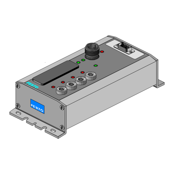
- Page 1 Compact Performance Description Electronics CP fieldbus node 5 Programming and diagnosis Type CP-FB5-E Fieldbus protocols: - Festo fieldbus - ABB CS 31 - Moeller SUCOnet K Description 165 205 en 0112a...
- Page 3 ....... . . 165 205 E (Festo AG & Co., D-73726 Esslingen, Federal Republic of Germany 2001) Internet: http://www.festo.com...
- Page 4 Contents and general instructions Festo P.BE-CP-FB5-E-EN en 0112a...
-
Page 5: Table Of Contents
........2-17 Festo P.BE-CP-FB5-E-EN en 0112a... - Page 6 ............Festo P.BE-CP-FB5-E-EN en 0112a...
-
Page 7: Designated Use
Festo Fieldbus, ABB CS31 and Moeller SU- COnet K. CP modules from Festo can be connected to CP field bus node CP-FB5-E. The CP node may only be used as fol- lows: –... -
Page 8: Target Group
Service Please consult your local Festo repair service if you have any technical problems. Notes on the use of this manual This manual contains specific information on installing, com- missioning, programming and diagnosing CP field bus node FB5. -
Page 9: Important User Instructions
... This means that failure to observe this instruction may result in damage to property. The following pictogram marks passages in the text which describe activities with electrostatically sensitive compo- nents. Electrostatically sensitive components may be damaged if they are not handled correctly. Festo P.BE-CP-FB5-E-EN en 0112a... - Page 10 Accessories: Information on necessary or sensible accessories for the Festo product. Environment: Information on environment-friendly use of Festo products. Text markings The bullet indicates activites which may be carried out in any order. 1. Figures denote activities which must be carried out in the numerical order specified.
- Page 11 Information on fitting, commissioning, installing and commis- installing and commis- programming and sioning CPA or CPV sioning CP I/O diagnosing related to valve terminals modules the node used b b b b Fig. 0/1: CP system manuals Festo P.BE-CP-FB5-E-EN en 0112a...
- Page 12 Total number of I/O modules connected together on one CP connection String of the field bus node Total number of all the I/O modules connected via strings to a CP field String assignment bus node (0...3) Festo P.BE-CP-FB5-E-EN en 0112a...
-
Page 13: Installation
Installation Chapter 1 Festo P.BE-CP-FB5-E-EN en 0112a... - Page 14 ..........1-16 Festo P.BE-CP-FB5-E-EN en 0112a...
-
Page 15: General Instructions
S Do not therefore touch any components. S Observe the regulations for handling electrostatically vulnerable components. You thereby avoid damage to the electronic components of the node. General information on installing CP modules can be found in the manual “CP system.” Festo P.BE-CP-FB5-E-EN en 0112a... -
Page 16: Setting The Dil Switches
DIL switch elements 1 .. 6. S During operation: do not change the DIL switch settings. You thereby avoid undesired reactions of the connected actuators. DIL switch POWER POWER V Fig. 1/1: Position of the DIL switch Festo P.BE-CP-FB5-E-EN en 0112a... - Page 17 1. Installation Dual inline switch Set the following functions on the DIL switch: – the field bus protocol – the field bus baud rate ( only required with Festo proto- col) DIL switch Switch Description of function (factory set- element...
-
Page 18: Setting The Field Bus Address
Set the field bus address of the CP system with the two round address selector switches. The switches are numbered from 0..9. The arrow indicates the units or tens figure of the field bus address which is set. Festo P.BE-CP-FB5-E-EN en 0112a... - Page 19 Festo Field bus address 1; 2; ...; 98 ABB Procontic CS31 module address 0; 1; ...; 60*) Moeller 2; ...; 98 *) depends on controller and on equipment fitted on the CP system (see chapter 2.3) Festo P.BE-CP-FB5-E-EN en 0112a...
- Page 20 3. Use a screwdriver to set the arrow on the relevant ad- dress selector switch to the units and tens figures of the desired field bus address. Examples Set field bus address: Set field bus address: Fig. 1/3: Example of set field bus addresses Festo P.BE-CP-FB5-E-EN en 0112a...
- Page 21 1. Installation 1.2.2 Setting the field bus baud rate Please note The desired baud rate need only be set with the Festo pro- tocol. With the protocols SUCOnet K and CS31, baud rate identifi- cation is made automatically. If you are using the Festo protocol, set the desired field bus baud rate on switch elements 1 and 2.
-
Page 22: Setting The Field Bus Protocol
Fig. 1/5: Settings with hardware status 06/97 or later Settings with hardware status 05/97 or earlier DIL switch Festo field bus ABB CS31 Moeller SUCOnet K Fig. 1/6: Settings with hardware status 05/97 or earlier 1-10 Festo P.BE-CP-FB5-E-EN en 0112a... -
Page 23: Connecting The Cp Modules
1. Installation Connecting the CP modules Warning S Use the special CP cables from Festo (type KVI-CP-1-...) for connecting the CP modules to a string. S Note that the total length of the cable on a string must not exceed 10 m. -
Page 24: Connecting The Operating Voltage
By the use of PELV power units, protection against electric shock (protection against direct and indirect contact) is guar- anteed with the Festo valve terminals in accordance with EN 60204-1/IEC 204. Safety transformers with the adjacent symbol must be used for supplying PELV networks. The valve terminals must be earthed to ensure that they function cor- rectly (e.g. -
Page 25: Connecting The Field Bus Interface
Signal attenuations are caused by: – transmission over long distances – unsuitable cables If you are using the Festo IP65 plug, the cable must have a diameter of 6 - 9 mm. A twisted, screened two-core cable must be used as the field bus cable. - Page 26 Clamp the screening of the field bus cable under the cable clip of the Festo plug (see diagram). Please note The cable clip in the Festo plug is internally connected ca- pacitively with the metallic housing of the sub-D plug. This is to prevent equalizing currents from flowing via the screening of the field bus cable (see diagram).
- Page 27 (IP65) field bus mod field bus mod- CS31 CS31 Sub-D DIN (round) 9-pin 5-pin Bus 1 3 (T 4 (T Bus 2 7 (T 1 (T Housing Cable clip Screening Screening/ 4 (screening) Housing shield 1-15 Festo P.BE-CP-FB5-E-EN en 0112a...
-
Page 28: Connecting The Bus
If the CP system is at the end of the field bus system, a bus terminator is necessary. Recommendation. Use the sub-D plug from Festo (part no. 18529) for this pur- pose. A suitable resistor network is incorporated in the hous- ing of the Festo sub-D plug. The bus terminator must be switched manually: (ON/OFF). -
Page 29: Commissioning
Commissioning Chapter 2 Festo P.BE-CP-FB5-E-EN en 0112a... - Page 30 ........2-17 Festo P.BE-CP-FB5-E-EN en 0112a...
-
Page 31: Preparing The Cp System For Operation On The Field Bus
1. Connect the operating voltage of the node (see manual “CP system”). 2. Connect the CP modules. 3. Switch on the operating voltage. 4. Save the string assignment by pressing the SAVE key. 5. Switch off the operating voltage of the node. Festo P.BE-CP-FB5-E-EN en 0112a... -
Page 32: Festo Fieldbus
The entry mask for the field bus configurator shows IW and OW on the screen. This means input and output words with 8 bits each. Enter 2 IW and 2 OW per string (16 inputs and 16 outputs). Festo P.BE-CP-FB5-E-EN en 0112a... - Page 33 2. Commissioning Fig. 2/1: Example – Configuring with FST 203; select CP system from type file Fig. 2/2: Example – Configuring with FST 203; enter the number of IW and OW Festo P.BE-CP-FB5-E-EN en 0112a...
-
Page 34: Addressing
The following example shows the addressing of the inputs/ puts outputs with 3 assigned strings (field bus address of CP system: 3). Example Master: Festo SF3 Configuration with FST200: 6 IW and 6 OW Field bus address of CP system: Festo P.BE-CP-FB5-E-EN en 0112a... - Page 35 String unused, but address range assigned (reserved) E = input; A = output Fig. 2/3: Addressing the CP system Further details on addressing and programming can be found in the PLC manual for your controller (e.g. Festo manual FST200). Festo P.BE-CP-FB5-E-EN en 0112a...
-
Page 36: Abb Cs31
The appropriate module identifiers must be entered in the configuration table of the T200. Please note If possible, select the range n = 0...58 for the address to be set in the CP node. n+3 < 61 can then also be addressed. Festo P.BE-CP-FB5-E-EN en 0112a... -
Page 37: Cs 31 Central Processing Unit As Bus Master
E n+2,00 ... E n+2,15 A n+3,00 ... A n+3,15 E n+3,00 ... E n+3,15 n = station number; E = input; A = output Fig. 2/4: Configuration possibilities and addresses for a CS 31 central processing unit Festo P.BE-CP-FB5-E-EN en 0112a... - Page 38 E12,0 ... E12,15 POWER POWER V A14,0 ... A14,15 E14,0 ... E14,15 String unused, but address range assigned (reserved) E = input; A = output Fig. 2/5: Example – addressing with a 07KR91 central processing unit 2-10 Festo P.BE-CP-FB5-E-EN en 0112a...
-
Page 39: T200/07Cs61 As Bus Master
With the aid of programming system 07 PC 332, enter here the appropriate module identifiers in the configuration table (per string IO16; see examples). 2-11 Festo P.BE-CP-FB5-E-EN en 0112a... - Page 40 The configuration list shown applies to line 1. CP systems entered: – Address in CP node: 20 32 inputs, 32 outputs – Address in field bus node: 33 64 inputs, 64 outputs Fig. 2/6: Examples – module identifiers 2-12 Festo P.BE-CP-FB5-E-EN en 0112a...
- Page 41 A I.n+3,00 ... A I.n+3,15 E I.n+3,00 ... E I.n+3,15 I = line; n = set address; E = input; A = output Fig. 2/7: Possibilities of configuration or addressing with T200 as bus master 2-13 Festo P.BE-CP-FB5-E-EN en 0112a...
- Page 42 E1.20,0 ... E1.20,15 POWER POWER V A1.22,0 ... A1.22,15 E1.22,0 ... E1.22,15 String unused, but address range assigned (reserved) E = input; A = output Fig. 2/8: Example – addressing with T200/07CS61 as central processing unit 2-14 Festo P.BE-CP-FB5-E-EN en 0112a...
-
Page 43: Moeller Suconet K
The following diagram shows the configuration entries for a CP system using the example of a PS4-201 as master. 3 or 4 CP strings occupied 1 or 2 CP strings occupied Fig. 2/9: Configuration on the SUCOnet K 2-15 Festo P.BE-CP-FB5-E-EN en 0112a... - Page 44 The topology configurator from Moeller can be used for Windows configuring bus slaves. Icon for CP valve terminal - SIS-K-10/10 assigned for 3 or 4 strings - SIS-K-06/07 assigned for 1 or 2 strings Fig. 2/10: Configuration entries in the topology configurator 2-16 Festo P.BE-CP-FB5-E-EN en 0112a...
-
Page 45: Addressing Inputs/Outputs
The slave number or the number of the unit differs from the set station number by -1. Example: Set field bus address Number of unit or slave number of the CP system Fig. 2/11: Example of assignment of units 2-17 Festo P.BE-CP-FB5-E-EN en 0112a... - Page 46 RD1.1.0.0.0 ... RD1.1.0.0.7 SD1.1.0.1.0 ... SD1.1.0.1.7 POWER POWER V SD1.1.0.4.0 ... SD1.1.0.4.7 RD1.1.0.4.0 ... RD1.1.0.4.7 SD1.1.0.5.0 ... SD1.1.0.5.7 String unused, but address range assigned (reserved) Fig. 2/12: Example – addressing the inputs/outputs with PS 4-201 2-18 Festo P.BE-CP-FB5-E-EN en 0112a...
-
Page 47: Diagnosis
Diagnosis Chapter 3 Festo P.BE-CP-FB5-E-EN en 0112a... - Page 48 ......3-18 3.4.3 Short circuit in sensor supply at an input module ..... 3-19 Festo P.BE-CP-FB5-E-EN en 0112a...
-
Page 49: Diagnosis
The LEDs on the node enable you to make a quick on-the-spot diagnosis of the operating status of the CP system. Bus-specific LED Operating voltage LEDs String LEDs POWER POWER V Fig. 3/1: LEDs of CP node FB5 Festo P.BE-CP-FB5-E-EN en 0112a... -
Page 50: Normal Operating Status
= flashes; = off LEDs Colour Operating status Error treatment normal *) none BUS ERROR green POWER green POWER V *) Moeller: LED flashes until input/output of CP system is addressed first time by the master Festo P.BE-CP-FB5-E-EN en 0112a... -
Page 51: Diagnostic Operating Voltage Power Or Power
Operating voltage of valves (pin 2) not within tolerance valves (pin 2) POWER V flashes range. S Check operating voltage con- Operating voltage of electronic POWER components (pin 1) not applied nection Hardware error Servicing required Festo P.BE-CP-FB5-E-EN en 0112a... -
Page 52: Diagnosis Led Bus Error
Correct field bus address BUS ERROR flashes fast mitted Festo: 1;...; 98 ABB: 0;...; 60 with Festo: S1, S2 incorretly Moeller: 2;...; 98 Field bus connection not OK. Check the ... BUS ERROR flashes slowly Possible causes: S setting of the address se- (1 second inter- –... -
Page 53: Testing The Valves
– None of the programmed locking or further switching conditions will taken into account. Test routine During the test routine of the CP terminal all the valves will be switched on and off at 1 second intervals. Festo P.BE-CP-FB5-E-EN en 0112a... -
Page 54: Starting The Test Routine
2. Reset the address selector switch and the DIL switch el- ements to their original positions again. Switch on the operating voltage supply again when the test routine is concluded: on the node on the output modules Festo P.BE-CP-FB5-E-EN en 0112a... -
Page 55: Diagnosis Of The Field Bus
SC/O – Common message: short circuit / overload at output modules – Common message: connection to CP module(s) interrupted (valve terminal, input/output module) Fig. 3/2: Summary of diagnostic bits Festo P.BE-CP-FB5-E-EN en 0112a... -
Page 56: Festo Fieldbus
3. Diagnosis 3.3.1 Festo fieldbus All diagnostic information can be evaluated directly with a Festo PLC. An error list is created in the master for this pur- pose. All diagnostic bits are included in this error list and are continually updated. -
Page 57: Abb Cs31
CS31 system bus and local modules. The relevant ABB manuals apply to all central processing units and couplers. The following table shows as an example the diagnostic possibilities in conjunction with: – central processing unit 07KR91 – coupler 07CS61 3-11 Festo P.BE-CP-FB5-E-EN en 0112a... - Page 58 – Common message: short circuit in sensor voltage supply – Common message: failure of load voltage supply at output modules SC/O – Common message: short circuit/overload at output modules Fig. 3/4: Diagnostic information – example 07KR91 3-12 Festo P.BE-CP-FB5-E-EN en 0112a...
- Page 59 MW 255,13 MW 255,06 MW 255,14 MW 255,07 MW 255,15 Fault recognition / Meaning on Festo CP systems = CP system not connected Unit type: 4 = Binary inputs / outputs Group no. (set field bus address, decimal) = internal module fault (CP system diagnostic bit: V...
- Page 60 = Error word 7, FW 4104,10 faulty configuration Common message; error code: 1111 no fault 1011 remote unit error *) 1101 bus fault 1110 serial unit error Fig. 3/6: Example line 1: Entering diagnostic information (continued next page) 3-14 Festo P.BE-CP-FB5-E-EN en 0112a...
- Page 61 CP system always 0 CS31 Module address (= set field bus address) Binary module (= CP system) Analogue module is modified by CP system Fig. 3/7: Continuation of example for line 1: entering diagnostic information 3-15 Festo P.BE-CP-FB5-E-EN en 0112a...
-
Page 62: Moeller Suconet K
KCP* Vval* Vtol* Vsen* Voff* SC/O* ACP* — Signal status Meaning Signal status “0”: no fault Signal status “1”: fault * Explanation see chapter 3.3 Fig. 3/9: Structure of diagnostic byte of Moeller SUCOnet K 3-16 Festo P.BE-CP-FB5-E-EN en 0112a... -
Page 63: Error Treatment
3.4.1 Reaction of the CP valve terminal to faults Please note Unilaterally-actuated valves move to the basic position. Double solenoid valves remain in the current position. If mid-position functions are implemented by CP valves, these move to defined positions (pressurized, exhausted, blocked). 3-17 Festo P.BE-CP-FB5-E-EN en 0112a... -
Page 64: Short Circuit/Overload At An Output Module
– All outputs of the CP system are reset auto- CP system at the field bus node matically The outputs can then be set at “logic 1” again. If the short circuit still exists, the outputs will be switched off again. 3-18 Festo P.BE-CP-FB5-E-EN en 0112a... -
Page 65: Short Circuit In Sensor Supply At An Input Module
CP connection at the CP input module briefly interrupt the operating voltage of the CP system at the field bus node The inputs can then be interrogated again. If the short circuit/ overload still exists, the error will be displayed again. 3-19 Festo P.BE-CP-FB5-E-EN en 0112a... - Page 66 3. Diagnosis 3-20 Festo P.BE-CP-FB5-E-EN en 0112a...
- Page 67 Technical Appendix Appendix A Festo P.BE-CP-FB5-E-EN en 0112a...
-
Page 68: A. Technical Appendix
............Festo P.BE-CP-FB5-E-EN en 0112a... -
Page 69: A.1 Technical Specifications Of The Field Bus Node Cp Fb5-E
Residual ripple 4 Vpp (within tolerance) Power failure bridging time 20 ms Electromagnetic compatibility Interference emission – tested as per EN 55011 Limit values class B*) Resistance to interference – tested as per EN 50082-2 Festo P.BE-CP-FB5-E-EN en 0112a... - Page 70 ABB Procontic CS31 SUCOnet K Baud rate 31.25 kBaud 62.5 kBaud 187.5 kBaud kBaud Cable length up to 4000 m Cable type see manual for your controller Maximum loading supply voltage positive (P5V) pin 6 max. 40 mA Festo P.BE-CP-FB5-E-EN en 0112a...
-
Page 71: A.2 Index
......1-13 operating voltage ......1-12 Festo P.BE-CP-FB5-E-EN en 0112a... - Page 72 ....... Error treatment, CP valve terminal ....3-17 Festo P.BE-CP-FB5-E-EN en 0112a...
- Page 73 ........3-16 Notes on the use of this manual ..... . Festo P.BE-CP-FB5-E-EN en 0112a...
- Page 74 ......... . Festo P.BE-CP-FB5-E-EN en 0112a...
Need help?
Do you have a question about the CP-FB5-E and is the answer not in the manual?
Questions and answers