
Related Manuals for Beckhoff EL2124


Summary of Contents for Beckhoff EL2124
- Page 1 Documentation EL20xx, EL2124 Digital Output Terminals Version: Date: 2019-06-06...
-
Page 3: Table Of Contents
EL2088 - LEDs and connection .................. 57 EL2124 - Introduction ........................ 58 2.7.1 EL2124 - Technical data.................... 59 2.7.2 EL2124 - LEDs and connection .................. 60 3 Basics communication ........................... 61 EtherCAT basics.......................... 61 EtherCAT cabling – wire-bound....................... 61 General notes for setting the watchdog ................... 62 EtherCAT State Machine ......................... 64... - Page 4 Device description ESI file/XML.................. 152 6.4.2 Firmware explanation .................... 155 6.4.3 Updating controller firmware *.efw................. 156 6.4.4 FPGA firmware *.rbf....................... 157 6.4.5 Simultaneous updating of several EtherCAT devices............ 161 Restoring the delivery state ...................... 162 Support and Service ........................ 163 Version: 5.2 EL20xx, EL2124...
-
Page 5: Foreword
, TwinSAFE , XFC and XTS registered trademarks of and licensed by Beckhoff Automation GmbH. Other designations used in this publication may be trademarks whose use by third parties for their own purposes could violate the rights of the owners. - Page 6 Foreword ® EtherCAT is registered trademark and patented technology, licensed by Beckhoff Automation GmbH, Germany. Copyright © Beckhoff Automation GmbH & Co. KG, Germany. The reproduction, distribution and utilization of this document as well as the communication of its contents to others without express authorization are prohibited.
-
Page 7: Safety Instructions
All the components are supplied in particular hardware and software configurations appropriate for the application. Modifications to hardware or software configurations other than those described in the documentation are not permitted, and nullify the liability of Beckhoff Automation GmbH & Co. KG. Personnel qualification This description is only intended for trained specialists in control, automation and drive engineering who are familiar with the applicable national standards. -
Page 8: Documentation Issue Status
- "Device description update" amended - Trademark notes added - Technical description amended, EL2042 amended - Technical description amended, EL2024-0010 amended - Technical description amended, EL2124 amended - Technical description amended - Technical data amended, watchdog documentation amended - Terminals EL2022, EL2024, EL2034 added... -
Page 9: Version Identification Of Ethercat Devices
Production lot/batch number/serial number/date code/D number The serial number for Beckhoff IO devices is usually the 8-digit number printed on the device or on a sticker. The serial number indicates the configuration in delivery state and therefore refers to a whole production batch, without distinguishing the individual modules of a batch. -
Page 10: Fig. 1 El5021 El Terminal, Standard Ip20 Io Device With Serial/ Batch Number And Revision Id (Since 2014/01)
• IP67: EtherCAT Box • Safety: TwinSafe • Terminals with factory calibration certificate and other measuring terminals Examples of markings Fig. 1: EL5021 EL terminal, standard IP20 IO device with serial/ batch number and revision ID (since 2014/01) Version: 5.2 EL20xx, EL2124... -
Page 11: Fig. 2 Ek1100 Ethercat Coupler, Standard Ip20 Io Device With Serial/ Batch Number
Foreword Fig. 2: EK1100 EtherCAT coupler, standard IP20 IO device with serial/ batch number Fig. 3: CU2016 switch with serial/ batch number Fig. 4: EL3202-0020 with serial/ batch number 26131006 and unique ID-number 204418 EL20xx, EL2124 Version: 5.2... -
Page 12: Fig. 5 Ep1258-00001 Ip67 Ethercat Box With Batch Number/ Date Code 22090101 And Unique Se- Rial Number 158102
Fig. 6: EP1908-0002 IP67 EtherCAT Safety Box with batch number/ date code 071201FF and unique serial number 00346070 Fig. 7: EL2904 IP20 safety terminal with batch number/ date code 50110302 and unique serial number 00331701 Fig. 8: ELM3604-0002 terminal with unique ID number (QR code) 100001051 and serial/ batch number 44160201 Version: 5.2 EL20xx, EL2124... -
Page 13: Non-Reactive Bus Terminals
60 V in the event of a fault. • Prevention of feedback Feedback can be prevented through different measures. These are described below. In addition to mandatory requirements there are also optional requirements, of which only one needs to be selected. EL20xx, EL2124 Version: 5.2... -
Page 14: Fig. 9 Negative Example - Active Load
This can be achieved, for example, through adherence to load-specific standards. ◦ Option 1: Ground feedback and all-pole disconnection The ground connection of the connected load must be fed back to the safely switched ground of the respective output terminal. Version: 5.2 EL20xx, EL2124... -
Page 15: Fig. 10 Ground Connection Of The Load: Correct (K1) And Incorrect (K2)
If solution option 1 is not feasible, the ground feedback and all-pole disconnection can be dispensed with if the danger of feedback due to a cable short-circuit can be excluded by other measures. These measures, which can be implemented alternatively, are described in the following sections. EL20xx, EL2124 Version: 5.2... -
Page 16: Fig. 11 Short Circuit Fault Exclusion Through Protected Cable Laying
Summary of safety classifications Feedback avoidance mea- DIN EN ISO 13849-1 IEC 61508 EN 62061 sures Fault exclusion max. max. SIL3 max. SIL2 * Cable short-circuit Cat. 4 Ground feedback and all- max. SIL3 pole disconnection Version: 5.2 EL20xx, EL2124... -
Page 17: Product Overview, Digital Output Terminals
They are protected against reverse polarity at the power contacts. The digital output terminals of the EL200x series indicate their signal state through an LED for each channel. EL20xx, EL2124 Version: 5.2... - Page 18 Product overview, digital output terminals CAUTION Watchdog settings Please refer to section "Notes for setting the watchdog [} 62]". Version: 5.2 EL20xx, EL2124...
-
Page 19: El2002, El2004, El2008 - Technical Data
Installation instructions for terminals with increased mechanical load capacity [} 74] EMC resistance burst/ESD conforms to EN 61000-6-2 / EN 61000-6-4 Protection class IP20 Installation position variable variable see note [} 78] Approval cULus [} 150] ATEX [} 82] EL20xx, EL2124 Version: 5.2... -
Page 20: El2002 - Leds And Connection
PE (internally connected to terminal point 8) Output 2 Output 2 +24 V +24 V (internally connected to terminal point 2 and positive power contact) 0 V Ground for output 2 (internally connected to terminal point 3 and negative power contact) PE (internally connected to terminal point 4) Version: 5.2 EL20xx, EL2124... -
Page 21: El2004 - Leds And Connection
Output 2 0 V Ground for output 2 (internally connected to terminal point 2, 3, 7 and negative power contact) 0 V Ground for output 4 (internally connected to terminal point 2, 3, 6 and negative power contact) Output 4 Output 4 EL20xx, EL2124 Version: 5.2... -
Page 22: El2008 - Leds And Connection
Terminal point Description Name Output 1 Output 1 Output 3 Output 3 Output 5 Output 5 Output 7 Output 7 Output 2 Output 2 Output 4 Output 4 Output 6 Output 6 Output 8 Output 8 Version: 5.2 EL20xx, EL2124... -
Page 23: El2014 - Introduction
The power contacts are continuous; reference potential of the outputs is the 0 V power contact. The outputs are fed via the 24 V power contact in the EL2014. NOTE Watchdog settings Please refer to section "Notes for setting the watchdog [} 62]". EL20xx, EL2124 Version: 5.2... -
Page 24: El2014 - Technical Data
35 mm mounting rail conforms to EN 60715 Mounting [} 72] Vibration/shock resistance conforms to EN 60068-2-6 / EN 60068-2-27 EMC immunity/emission conforms to EN 61000-6-2 / EN 61000-6-4 Protection class IP20 Installation position variable Approval IECEx Version: 5.2 EL20xx, EL2124... -
Page 25: El2014 - Leds And Pin Assignment
Output 2 0 V Ground for output 2 (internally connected to terminal point 2, 3, 7 and negative power contact) 0 V Ground for output 4 (internally connected to terminal point 2, 3, 6 and negative power contact) Output 4 Output 4 EL20xx, EL2124 Version: 5.2... -
Page 26: Overload Protection
The output signal is clocked until the output is switched off by the controller or the short-circuit is eliminated (see fig. Schematic illustration of the thermal switch-off in case of overload). The clock frequency depends on the ambient temperature and the load of the other terminal channels. Version: 5.2 EL20xx, EL2124... -
Page 27: Fig. 21 Switch-Off Of Inductive Loads
To protect against voltage peaks such as can occur when switching inductive loads, we recommend to provide suitable protective circuits (e.g. with the free-wheeling diode, RC combination or varistor) directly at the actuator. Fig. 21: Switch-off of inductive loads EL20xx, EL2124 Version: 5.2... -
Page 28: Operating Modes And Settings
The EL2014 provides three different process data for transmission: • the diagnostics per channel “DIG Diag Inputs” (16-bit), • the device diagnostics “DIG Inputs Device” (4-bit), • The switching state of the outputs “DIG output” (4-bit) Version: 5.2 EL20xx, EL2124... -
Page 29: Fig. 23 El2014 Online Illustration Of The Process Data And Structural Contents In The System Manager
• for all TwinCAT versions via the “Predefined PDO Assignment” selection dialog (see fig. “EL2014 Process Data tab” A) or • selectively for individual PDOs (see fig. “EL2014 Process Data tab” B) . These changes become effective after activation and an EtherCAT restart or a reload. EL20xx, EL2124 Version: 5.2... -
Page 30: Fig. 24 El2014 "Process Data" Tab
Outputs: PDO 0x1600 (switching state of the outputs) is displayed and transmitted. Compact Diagnostics, No Diagnostics When converting from “Full Diagnostics” to “Compact Diagnostics” or “No Diagnostics”, or when de- activating the PDO 0x1600, links already established to the deactivated objects are deleted. Version: 5.2 EL20xx, EL2124... - Page 31 If the “Undervoltage” bit (index 0xF600:13) is set, the supply voltage of the terminal has fallen below typically 17 V. Voltage loss (index 0xF600:14 [} 36]) If the error bit in “Missing Voltage” (index 0xF600:14) is set, the supply voltage of the terminal has fallen below typically 14 V. EL20xx, EL2124 Version: 5.2...
-
Page 32: Fig. 25 El2014 Coe Directory
The diagnostic data of the terminal can be read under “DIG Inputs Device” (index 0xF600). The state of the outputs can be read under “DIG Outputs Ch.n” (index 0x70n0) (C). The display in TwinCAT is continuously updated if (F) has been activated. Version: 5.2 EL20xx, EL2124... -
Page 33: Fig. 26 Change Of State Of The Outputs In The Case Of A Bus Error
◦ The state of the output is retained. Entries in “DIG Safe State Value” (index 0x80n1:01) have no effect. Flow-chart illustration of the sequence in case of a bus error Fig. 26: Change of state of the outputs in the case of a bus error EL20xx, EL2124 Version: 5.2... -
Page 34: Object Description And Parameterization
EtherCAT XML Device Description The display matches that of the CoE objects from the EtherCAT XML Device Description. We rec- ommend downloading the latest XML file from the download area of the Beckhoff website and in- stalling it according to installation instructions. - Page 35 Index FB00 DIG Command Index (hex) Name Meaning Data type Flags Default value FB00:0 DIG Command Maximum subindex UINT8 0x03 (3 FB00:01 Request reserved OCTET - STRING[2] FB00:02 Status reserved UINT8 0x00 (0 FB00:03 Response reserved OCTET - STRING[4] EL20xx, EL2124 Version: 5.2...
- Page 36 Default value 1000:0 Device type Device type of the EtherCAT slave: the Lo-Word con- UINT32 0x01181389 tains the CoE profile used (5001). The Hi-Word con- (18355081 tains the module profile according to the modular de- vice profile. Version: 5.2 EL20xx, EL2124...
- Page 37 0x7020:01, 1 Ch.03), entry 0x01 (Output)) 1600:04 SubIndex 004 4. PDO Mapping entry (object 0x7030 (DIG Outputs UINT32 0x7030:01, 1 Ch.04), entry 0x01 (Output)) 1600:05 SubIndex 005 5. PDO Mapping entry (4 bits align) UINT32 0x0000:00, 4 EL20xx, EL2124 Version: 5.2...
- Page 38 Sync-Manager Type Channel 2: Mailbox Read UINT8 0x02 (2 1C00:03 SubIndex 003 Sync-Manager Type Channel 3: Process Data Write UINT8 0x03 (3 (Outputs) 1C00:04 SubIndex 004 Sync-Manager Type Channel 4: Process Data Read UINT8 0x04 (4 (Inputs) Version: 5.2 EL20xx, EL2124...
- Page 39 TxPDO mapping object) (6658 1C13:03 Subindex 003 UINT16 1C13:04 Subindex 004 UINT16 1C13:05 Subindex 005 UINT16 1C32:06 Subindex 006 UINT16 1C13:07 Subindex 007 UINT16 1C13:08 Subindex 008 UINT16 1C13:09 Subindex 009 UINT16 1C13:0A Subindex 010 UINT16 EL20xx, EL2124 Version: 5.2...
- Page 40 Shift too short counter Number of occasions that the interval between SYNC0 UINT16 0x0000 (0 and SYNC1 event was too short (DC mode only) 1C32:20 Sync error The synchronization was not correct in the last cycle BOOLEAN 0x00 (0 (outputs were output too late; DC mode only) Version: 5.2 EL20xx, EL2124...
- Page 41 Modular device profile General information for the modular device profile UINT8 0x02 (2 F000:01 Module index distance Index spacing of the objects of the individual channels UINT16 0x0010 (16 F000:02 Maximum number of Number of channels UINT16 0x0004 (4 modules EL20xx, EL2124 Version: 5.2...
- Page 42 UINT32 0x00000118 agnostics) (280 F010:03 SubIndex 003 Profil 280 (Extended Digital Input and Output with Di- UINT32 0x00000118 agnostics) (280dec) F010:04 SubIndex 004 Profil 280 (Extended Digital Input and Output with Di- UINT32 0x00000118 agnostics) (280 Version: 5.2 EL20xx, EL2124...
-
Page 43: El2022, El2024, El2024-0010 - Introduction
LEDs. The EL2024 enables direct connection of four 2-wire actuators. It features four earth connecting points. The EL2024-0010 is a version with 12 V output. CAUTION Watchdog settings Please refer to section "Notes for setting the watchdog [} 62]". EL20xx, EL2124 Version: 5.2... -
Page 44: El2022, El2024, El2024-0010 - Technical Data
Installation instructions for terminals with increased mechanical load capacity [} 74] EMC resistance burst/ESD conforms to EN 61000-6-2 / EN 61000-6-4 Protection class IP20 Installation position variable Approval cULus [} 150] cULus [} 150] cULus [} 150] ATEX [} 82] ATEX [} 82] ATEX [} 81] IECEx Version: 5.2 EL20xx, EL2124... -
Page 45: El2022 - Leds And Connection
Output 2 +24 V +24 V (internally connected to terminal point 2 and positive power contact) Ground for output 2 (internally connected to terminal point 3 and negative power contact) PE contact (internally connected to terminal point 4 and PE power contact) EL20xx, EL2124 Version: 5.2... -
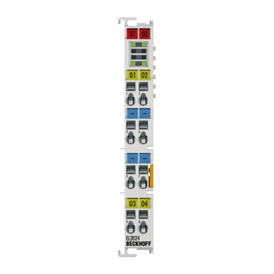
Page 46: El2024, El2024-0010 - Leds And Connection
Output 2 0 V Ground for output 2 (internally connected to terminal point 2, 3, 7 and negative power contact) 0 V Ground for output 4 (internally connected to terminal point 2, 3, 6 and negative power contact) Output 4 Output 4 Version: 5.2 EL20xx, EL2124... -
Page 47: El2032, El2034 - Introduction
The limit value is typically between 2 and 900 mA. The application of the "broken wire detection" function therefore makes sense for regular output currents of approx. 1 A or higher. CAUTION Watchdog settings Please refer to section "Notes for setting the watchdog [} 62]". EL20xx, EL2124 Version: 5.2... -
Page 48: El2032, El2034 - Technical Data
EN 60068-2-6/EN 60068-2-27, see also Installation instructions for terminals with increased mechanical load capacity [} 74] EMC resistance burst/ESD conforms to EN 61000-6-2 / EN 61000-6-4 Protection class IP20 Installation position variable Approval cULus [} 150] ATEX [} 82] Version: 5.2 EL20xx, EL2124... -
Page 49: El2032 - Leds And Connection
Output 2 +24 V +24 V (internally connected to terminal point 2 and positive power contact) 0 V Ground for output 2 (internally connected to terminal point 3 and negative power contact) PE contact (internally connected to terminal point 4 and PE power contact) EL20xx, EL2124 Version: 5.2... -
Page 50: El2034 - Leds And Connection
Output 2 0 V Ground for output 2 (internally connected to terminal point 2, 3, 7 and negative power contact) 0 V Ground for output 4 (internally connected to terminal point 2, 3, 6 and negative power contact) Output 4 Output 4 Version: 5.2 EL20xx, EL2124... -
Page 51: El2042 - Introduction
Two channels are available in each case, which indicate their signal state via LEDs. The EL2042 enables connection of loads with current consumption up to 8 A if the outputs are connected in parallel. CAUTION Watchdog settings Please refer to section "Notes for setting the watchdog [} 62]". EL20xx, EL2124 Version: 5.2... -
Page 52: El2042 - Technical Data
Vibration/shock resistance according to EN 60068-2-6/EN 60068-2-27, see also Installation instructions for terminals with increased me- chanical load capacity [} 74] EMC resistance burst/ESD conforms to EN 61000-6-2 / EN 61000-6-4 Protection class IP20 Installation position variable Approval Version: 5.2 EL20xx, EL2124... -
Page 53: El2042 - Leds And Connection
Ground for output 1 (internally connected to terminal point 7 and negative power contact) Output 2 Output 2 +24 V +24 V (internally connected to terminal point 2 and positive power contact) 0 V Ground for output 2 (internally connected to terminal point 3 and negative power contact) EL20xx, EL2124 Version: 5.2... -
Page 54: El2084, El2088 - Introduction
The EtherCAT Terminals have 0 V (ground) switching outputs and generate load currents with outputs that are resistant to overload and short-circuit. They include four or eight channels, whose signal state is indicated by LEDs. CAUTION Watchdog settings Please refer to section "Notes for setting the watchdog [} 62]". Version: 5.2 EL20xx, EL2124... -
Page 55: El2084, El2088 - Technical Data
Installation instructions for terminals with increased mechanical load capacity [} 74] EMC resistance burst/ESD conforms to EN 61000-6-2 / EN 61000-6-4 Protection class IP20 Installation position variable see note [} 78] Approval cULus [} 150] ATEX [} 81] EL20xx, EL2124 Version: 5.2... -
Page 56: El2084 - Leds And Connection
+24 V for output 2 (internally connected to terminal points 2, 3, 7 and positive power contact) 24 V +24 V for output 4 (internally connected to terminal points 2, 3, 6 and positive power contact) Output 4 Output 4 (0 V) Version: 5.2 EL20xx, EL2124... -
Page 57: El2088 - Leds And Connection
Output 1 (0 V) Output 3 Output 3 (0 V) Output 5 Output 5 (0 V) Output 7 Output 7 (0 V) Output 2 Output 2 (0 V) Output 4 Output 4 (0 V) Output 6 Output 6 (0 V) Output 8 Output 8 (0 V) EL20xx, EL2124 Version: 5.2... -
Page 58: El2124 - Introduction
Four-channel digital output terminal 5 V , CMOS output The digital output terminal EL2124 connects the binary control signals of the automation device in an electrically isolated manner to the actuators at the process level and generates load currents with outputs that are protected against overload and short-circuit. -
Page 59: El2124 - Technical Data
Product overview, digital output terminals 2.7.1 EL2124 - Technical data Technical data EL2124 Number of outputs Load type ohmic, inductive, lamp load Nominal output voltage 5 V (CMOS output) Switching times : < 1 µs typ.; T : < 1 µs typ. Output current max. per channel ±20 mA (short-circuit-proof) per channel, 8 mA signal current, type... -
Page 60: El2124 - Leds And Connection
EL2124 - Connection NOTE 5 V DC at the power contacts During configuration of the Bus Terminal block, please note that the power contacts of the EL2124 carry a voltage of 5 V (provided e.g. by an EL9505 power supply terminal). -
Page 61: Basics Communication
EtherCAT devices from Beckhoff. Recommended cables Suitable cables for the connection of EtherCAT devices can be found on the Beckhoff website! E-Bus supply A bus coupler can supply the EL terminals added to it with the E-bus system voltage of 5 V; a coupler is thereby loadable up to 2 A as a rule (see details in respective device documentation). -
Page 62: General Notes For Setting The Watchdog
The PDI watchdog monitors correct and timely process data communication with the ESC from the application side. The settings of the SM- and PDI-watchdog must be done for each slave separately in the TwinCAT System Manager. Version: 5.2 EL20xx, EL2124... - Page 63 The standard setting of 1000 for the SM watchdog corresponds to a release time of 100 ms. The value in multiplier + 2 corresponds to the number of basic 40 ns ticks representing a watchdog tick. The multiplier can be modified in order to adjust the watchdog time over a larger range. EL20xx, EL2124 Version: 5.2...
-
Page 64: Ethercat State Machine
EtherCAT master to the device in each state, particularly during the bootup of the slave. A distinction is made between the following states: • Init • Pre-Operational • Safe-Operational and • Operational • Boot The regular state of each EtherCAT slave after bootup is the OP state. Version: 5.2 EL20xx, EL2124... - Page 65 Before the EtherCAT master switches the EtherCAT slave from Safe-Op to Op it must transfer valid output data. In the Op state the slave copies the output data of the masters to its outputs. Process data and mailbox communication is possible. EL20xx, EL2124 Version: 5.2...
- Page 66 In the Boot state the slave firmware can be updated. The Boot state can only be reached via the Init state. In the Boot state mailbox communication via the file access over EtherCAT (FoE) protocol is possible, but no other mailbox communication and no process data communication. Version: 5.2 EL20xx, EL2124...
-
Page 67: Coe Interface
Not every EtherCAT device must have a CoE list. Simple I/O modules without dedicated processor usually have no variable parameters and therefore no CoE list. If a device has a CoE list, it is shown in the TwinCAT System Manager as a separate tab with a listing of the elements: EL20xx, EL2124 Version: 5.2... - Page 68 Data management If slave CoE parameters are modified online, Beckhoff devices store any changes in a fail-safe manner in the EEPROM, i.e. the modified CoE parameters are still available after a restart. The situation may be different with other manufacturers.
- Page 69 Changes in the local CoE list of the terminal are lost if the terminal is replaced. If a terminal is re- placed with a new Beckhoff terminal, it will have the default settings. It is therefore advisable to link all changes in the CoE list of an EtherCAT slave with the Startup list of the slave, which is pro- cessed whenever the EtherCAT fieldbus is started.
- Page 70 ◦ The actual current slave list is read. This may take several seconds, depending on the size and cycle time. ◦ The actual identity is displayed ◦ The firmware and hardware version of the equipment according to the electronic information is displayed ◦ Online is shown in green. Fig. 48: Online list Version: 5.2 EL20xx, EL2124...
-
Page 71: Distributed Clock
4.2 seconds) • The EtherCAT master automatically synchronizes the local clock with the master clock in the EtherCAT bus with a precision of < 100 ns. For detailed information please refer to the EtherCAT system description. EL20xx, EL2124 Version: 5.2... -
Page 72: Mounting And Wiring
To mount the mounting rails with a height of 7.5 mm under the terminals and couplers, you should use flat mounting connections (e.g. countersunk screws or blind rivets). Version: 5.2 EL20xx, EL2124... - Page 73 EL91xx, EL92xx) interrupt the power contacts and thus represent the start of a new supply rail. PE power contact The power contact labeled PE can be used as a protective earth. For safety reasons this contact mates first when plugging together, and can ground short-circuit currents of up to 125 A. EL20xx, EL2124 Version: 5.2...
-
Page 74: Installation Instructions For Enhanced Mechanical Load Capacity
10 frequency runs in 3 axes 6 Hz < f < 60 Hz displacement 0.35 mm, constant amplitude 60.1 Hz < f < 500 Hz acceleration 5 g, constant amplitude Shocks 1000 shocks in each direction, in 3 axes 25 g, 6 ms Version: 5.2 EL20xx, EL2124... -
Page 75: Connection
Standard wiring (ELxxxx / KLxxxx) Fig. 52: Standard wiring The terminals of ELxxxx and KLxxxx series have been tried and tested for years. They feature integrated screwless spring force technology for fast and simple assembly. EL20xx, EL2124 Version: 5.2... - Page 76 Ultrasonically "bonded" (ultrasonically welded) conductors Ultrasonically “bonded" conductors It is also possible to connect the Standard and High Density Terminals with ultrasonically "bonded" (ultrasonically welded) conductors. In this case, please note the tables concerning the wire-size width below! Version: 5.2 EL20xx, EL2124...
-
Page 77: Wiring
The cables are released, as usual, using the contact release with the aid of a screwdriver. See the following table for the suitable wire size width. EL20xx, EL2124 Version: 5.2... -
Page 78: Shielding
EL/KL terminals to face forward (see Fig. “Recommended distances for standard installation position”). The terminals are ventilated from below, which enables optimum cooling of the electronics through convection. "From below" is relative to the acceleration of gravity. Version: 5.2 EL20xx, EL2124... - Page 79 Other installation positions All other installation positions are characterized by different spatial arrangement of the mounting rail - see Fig “Other installation positions”. The minimum distances to ambient specified above also apply to these installation positions. EL20xx, EL2124 Version: 5.2...
-
Page 80: Positioning Of Passive Terminals
The passive terminals have no current consump- tion out of the E-Bus. To ensure an optimal data transfer, you must not directly string together more than 2 passive termi- nals! Examples for positioning of passive terminals (highlighted) Fig. 58: Correct positioning Version: 5.2 EL20xx, EL2124... -
Page 81: Atex - Special Conditions (Standard Temperature Range)
80°C at the wire branching points, then cables must be selected whose tempera- ture data correspond to the actual measured temperature values! • Observe the permissible ambient temperature range of 0 to 55°C for the use of Beckhoff fieldbus compo- nents standard temperature range in potentially explosive areas! •... -
Page 82: Atex - Special Conditions (Extended Temperature Range)
80°C at the wire branching points, then cables must be selected whose tempera- ture data correspond to the actual measured temperature values! • Observe the permissible ambient temperature range of -25 to 60°C for the use of Beckhoff fieldbus com- ponents with extended temperature range (ET) in potentially explosive areas! •... -
Page 83: Atex Documentation
Notes about operation of the Beckhoff terminal systems in potentially explosive ar- eas (ATEX) Pay also attention to the continuative documentation Notes about operation of the Beckhoff terminal systems in potentially explosive areas (ATEX) that is available in the download area of the Beckhoff homepage http:\\www.beckhoff.com! EL20xx, EL2124... -
Page 84: Commissioning
• "offline": The configuration can be customized by adding and positioning individual components. These can be selected from a directory and configured. ◦ The procedure for offline mode can be found under http://infosys.beckhoff.com: TwinCAT 2 → TwinCAT System Manager → IO - Configuration → Adding an I/O Device •... - Page 85 • Linked via the X001 port (RJ-45): EK1100 EtherCAT Coupler • Connected to the EK1100 EtherCAT coupler on the right (E-bus): EL2008 (8-channel digital output terminal 24 V DC; 0.5 A) • (Optional via X000: a link to an external PC for the user interface) EL20xx, EL2124 Version: 5.2...
- Page 86 Note that all combinations of a configuration are possible; for example, the EL1004 terminal could also be connected after the coupler, or the EL2008 terminal could additionally be connected to the CX2040 on the right, in which case the EK1100 coupler wouldn’t be necessary. Version: 5.2 EL20xx, EL2124...
- Page 87 If the intention is to address the TwinCAT runtime environment installed on a PLC as development environment remotely from another system, the target system must be made known first. In the menu under "Actions" → "Choose Target System...", via the symbol " " or the "F8" key, open the following window: EL20xx, EL2124 Version: 5.2...
- Page 88 Fig. 64: Specify the PLC for access by the TwinCAT System Manager: selection of the target system Once the target system has been entered, it is available for selection as follows (a password may have to be entered): After confirmation with "OK" the target system can be accessed via the System Manager. Version: 5.2 EL20xx, EL2124...
- Page 89 Confirm the message "Find new boxes", in order to determine the terminals connected to the devices. "Free Run" enables manipulation of input and output values in "Config mode" and should also be acknowledged. Based on the sample configuration [} 85] described at the beginning of this section, the result is as follows: EL20xx, EL2124 Version: 5.2...
- Page 90 TwinCAT PLC Control is the development environment for the creation of the controller in different program environments: TwinCAT PLC Control supports all languages described in IEC 61131-3. There are two text- based languages and three graphical languages. • Text-based languages ◦ Instruction List (IL) Version: 5.2 EL20xx, EL2124...
- Page 91 After starting TwinCAT PLC Control, the following user interface is shown for an initial project: Fig. 69: TwinCAT PLC Control after startup Sample variables and a sample program have been created and stored under the name "PLC_example.pro": EL20xx, EL2124 Version: 5.2...
- Page 92 Manager has been notified, the warning no longer appears. First, integrate the TwinCAT PLC Control project in the System Manager via the context menu of the PLC configuration; right-click and select "Append PLC Project…": Fig. 71: Appending the TwinCAT PLC Control project Version: 5.2 EL20xx, EL2124...
- Page 93 "PLC_example" and via "Modify Link..." "Standard": Fig. 73: Creating the links between PLC variables and process objects In the window that opens, the process object for the variable “bEL1004_Ch4” of type BOOL can be selected from the PLC configuration tree: EL20xx, EL2124 Version: 5.2...
- Page 94 The links can also be checked by selecting a "Goto Link Variable” from the context menu of a variable. The object opposite, in this case the PDO, is automatically selected: Version: 5.2 EL20xx, EL2124...
- Page 95 The PLC system can then be started as described below. Starting the controller Starting from a remote system, the PLC control has to be linked with the Embedded PC over Ethernet via "Online" → “Choose Run-Time System…": EL20xx, EL2124 Version: 5.2...
- Page 96 This results in the message "No program on the controller! Should the new program be loaded?", which should be acknowledged with "Yes". The runtime environment is ready for the program start: Version: 5.2 EL20xx, EL2124...
- Page 97 (cf. "TwinCAT System Manager" of TwinCAT 2) for communication with the electromechanical components. After successful installation of the TwinCAT system on the PC to be used for development, TwinCAT 3 (shell) displays the following user interface after startup: EL20xx, EL2124 Version: 5.2...
- Page 98 First create a new project via (or under "File"→“New"→ "Project…"). In the following dialog make the corresponding entries as required (as shown in the diagram): Fig. 80: Create new TwinCAT project The new project is then available in the project folder explorer: Version: 5.2 EL20xx, EL2124...
- Page 99 Via the symbol in the menu bar: expand the pull-down menu: and open the following window: Fig. 82: Selection dialog: Choose the target system EL20xx, EL2124 Version: 5.2...
- Page 100 The TwinCAT System Manager may first have to be set to "Config mode" via or via the menu "TwinCAT" → "Restart TwinCAT (Config mode)". Fig. 84: Select "Scan" Confirm the warning message, which follows, and select "EtherCAT" in the dialog: Version: 5.2 EL20xx, EL2124...
- Page 101 The whole process consists of two stages, which may be performed separately (first determine the devices, then determine the connected elements such as boxes, terminals, etc.). A scan can also be initiated by selecting "Device ..." from the context menu, which then reads the elements present in the configuration below: EL20xx, EL2124 Version: 5.2...
- Page 102 The following section refers to Structured Text (ST). In order to create a programming environment, a PLC subproject is added to the project sample via the context menu of "PLC" in the project folder explorer by selecting "Add New Item….": Version: 5.2 EL20xx, EL2124...
- Page 103 Fig. 89: Specifying the name and directory for the PLC programming environment The "Main" program, which already exists by selecting "Standard PLC project", can be opened by double- clicking on "PLC_example_project" in "POUs”. The following user interface is shown for an initial project: EL20xx, EL2124 Version: 5.2...
- Page 104 Commissioning Fig. 90: Initial "Main" program of the standard PLC project To continue, sample variables and a sample program have now been created: Version: 5.2 EL20xx, EL2124...
- Page 105 "Assignments" in the project folder explorer: Assigning variables Via the menu of an instance - variables in the "PLC” context, use the "Modify Link…" option to open a window for selecting a suitable process object (PDO) for linking: EL20xx, EL2124 Version: 5.2...
- Page 106 4 of the EL1004 terminal is selected for linking. In contrast, the checkbox "All types" must be ticked for creating the link for the output variables, in order to allocate a set of eight separate output bits to a byte variable. The following diagram shows the whole process: Version: 5.2 EL20xx, EL2124...
- Page 107 PDO, it is possible to allocate this a set of bit-standardised variables (type "BOOL"). Here, too, a "Goto Link Variable” from the context menu of a PDO can be executed in the other direction, so that the respective PLC instance can then be selected. EL20xx, EL2124 Version: 5.2...
- Page 108 Fig. 97: TwinCAT development environment (VS shell): logged-in, after program startup The two operator control elements for stopping and logout result in the required action (accordingly also for stop "Shift + F5", or both actions can be selected via the PLC menu). Version: 5.2 EL20xx, EL2124...
-
Page 109: Twincat 2
5.2.1 Installation of the TwinCAT real-time driver In order to assign real-time capability to a standard Ethernet port of an IPC controller, the Beckhoff real-time driver has to be installed on this port under Windows. This can be done in several ways. One option is described here. - Page 110 Alternatively an EtherCAT-device can be inserted first of all as described in chapter Offline configuration creation, section “Creating the EtherCAT device” [} 120] in order to view the compatible ethernet ports via its EtherCAT properties (tab „Adapter“, button „Compatible Devices…“): Version: 5.2 EL20xx, EL2124...
- Page 111 After the installation the driver appears activated in the Windows overview for the network interface (Windows Start → System Properties → Network) Fig. 102: Windows properties of the network interface A correct setting of the driver could be: EL20xx, EL2124 Version: 5.2...
- Page 112 Commissioning Fig. 103: Exemplary correct driver setting for the Ethernet port Other possible settings have to be avoided: Version: 5.2 EL20xx, EL2124...
- Page 113 Commissioning Fig. 104: Incorrect driver settings for the Ethernet port EL20xx, EL2124 Version: 5.2...
- Page 114 DHCP. In this way the delay associated with the DHCP client for the Ethernet port assigning itself a default IP address in the absence of a DHCP server is avoided. A suitable address space is 192.168.x.x, for example. Fig. 105: TCP/IP setting for the Ethernet port Version: 5.2 EL20xx, EL2124...
-
Page 115: Notes Regarding Esi Device Description
The files are read (once) when a new System Manager window is opened, if they have changed since the last time the System Manager window was opened. A TwinCAT installation includes the set of Beckhoff ESI files that was current at the time when the TwinCAT build was created. - Page 116 1018 in the configuration. This is also stated by the Beckhoff compatibility rule. Refer in particular to the chapter ‘General notes on the use of Beckhoff EtherCAT IO components’ and for manual configuration to the chapter ‘Offline configuration creation’ [} 120].
- Page 117 Faulty ESI file If an ESI file is faulty and the System Manager is unable to read it, the System Manager brings up an information window. Fig. 111: Information window for faulty ESI file (left: TwinCAT 2; right: TwinCAT 3) EL20xx, EL2124 Version: 5.2...
- Page 118 Commissioning Reasons may include: • Structure of the *.xml does not correspond to the associated *.xsd file → check your schematics • Contents cannot be translated into a device description → contact the file manufacturer Version: 5.2 EL20xx, EL2124...
-
Page 119: Twincat Esi Updater
Commissioning 5.2.3 TwinCAT ESI Updater For TwinCAT 2.11 and higher, the System Manager can search for current Beckhoff ESI files automatically, if an online connection is available: Fig. 112: Using the ESI Updater (>= TwinCAT 2.11) The call up takes place under: “Options” → "Update EtherCAT Device Descriptions"... -
Page 120: Offline Configuration Creation
EL6601/EL6614 terminal select “EtherCAT Automation Protocol via EL6601”. Fig. 115: Selecting the EtherCAT connection (TwinCAT 2.11, TwinCAT 3) Then assign a real Ethernet port to this virtual device in the runtime system. Fig. 116: Selecting the Ethernet port Version: 5.2 EL20xx, EL2124... - Page 121 Fig. “Selection dialog for new EtherCAT device”. If the preceding device has several free ports (e.g. EK1122 or EK1100), the required port can be selected on the right-hand side (A). Overview of physical layer • “Ethernet”: cable-based 100BASE-TX: EK couplers, EP boxes, devices with RJ45/M8/M12 connector EL20xx, EL2124 Version: 5.2...
- Page 122 (i.e. highest) revision and therefore the latest state of production is displayed in the selection dialog for Beckhoff devices. To show all device revisions available in the system as ESI descriptions tick the “Show Hidden Devices” check box, see Fig. “Display of previous revisions”.
- Page 123 If current ESI descriptions are available in the TwinCAT system, the last revision offered in the selection dialog matches the Beckhoff state of production. It is recommended to use the last device revision when creating a new configuration, if current Beckhoff devices are used in the real application. Older revisions should only be used if older devices from stock are to be used in the application.
- Page 124 Commissioning Fig. 123: EtherCAT terminal in the TwinCAT tree (left: TwinCAT 2; right: TwinCAT 3) Version: 5.2 EL20xx, EL2124...
-
Page 125: Online Configuration Creation
This scan mode attempts to find not only EtherCAT devices (or Ethernet ports that are usable as such), but also NOVRAM, fieldbus cards, SMB etc. However, not all devices can be found automatically. Fig. 126: Note for automatic device scan (left: TwinCAT 2; right: TwinCAT 3) EL20xx, EL2124 Version: 5.2... - Page 126 [} 130] with the defined initial configuration.Background: since Beckhoff occasionally increases the revision version of the delivered products for product maintenance reasons, a configuration can be created by such a scan which (with an identical machine construction) is identical according to the device list;...
- Page 127 Likewise, A might create spare parts stores worldwide for the coming series-produced machines with EL2521-0025-1018 terminals. After some time Beckhoff extends the EL2521-0025 by a new feature C. Therefore the FW is changed, outwardly recognizable by a higher FW version and a new revision -1019. Nevertheless the new device naturally supports functions and interfaces of the predecessor version(s);...
- Page 128 Fig. 135: Displaying of “Free Run” and “Config Mode” toggling right below in the status bar Fig. 136: TwinCAT can also be switched to this state by using a button (left: TwinCAT 2; right: TwinCAT 3) The EtherCAT system should then be in a functional cyclic state, as shown in Fig. “Online display example”. Version: 5.2 EL20xx, EL2124...
- Page 129 The connections and devices should be checked in a targeted manner, e.g. via the emergency scan. Then re-run the scan. Fig. 138: Faulty identification In the System Manager such devices may be set up as EK0000 or unknown devices. Operation is not possible or meaningful. EL20xx, EL2124 Version: 5.2...
- Page 130 A ‘ChangeTo’ or ‘Copy’ should only be carried out with care, taking into consideration the Beckhoff IO compatibility rule (see above). The device configuration is then replaced by the revision found; this can affect the supported process data and functions.
- Page 131 If current ESI descriptions are available in the TwinCAT system, the last revision offered in the selection dialog matches the Beckhoff state of production. It is recommended to use the last device revision when creating a new configuration, if current Beckhoff devices are used in the real application. Older revisions should only be used if older devices from stock are to be used in the application.
- Page 132 This function is preferably to be used on AX5000 devices. Change to Alternative Type The TwinCAT System Manager offers a function for the exchange of a device: Change to Alternative Type Fig. 144: TwinCAT 2 Dialog Change to Alternative Type Version: 5.2 EL20xx, EL2124...
-
Page 133: Ethercat Subscriber Configuration
Here you can add a comment (e.g. regarding the system). Disabled Here you can deactivate the EtherCAT device. Create symbols Access to this EtherCAT slave via ADS is only available if this control box is activated. EL20xx, EL2124 Version: 5.2... - Page 134 CANopen process data objects (Process Data Objects, PDOs). The user can select a PDO via PDO assignment and modify the content of the individual PDO via this dialog, if the EtherCAT slave supports this function. Version: 5.2 EL20xx, EL2124...
- Page 135 For Beckhoff EtherCAT EL, ES, EM, EJ and EP slaves the following applies in general: • The input/output process data supported by the device are defined by the manufacturer in the ESI/XML description.
- Page 136 (CoE) or Servo drive over EtherCAT protocol. This tab indicates which download requests are sent to the mailbox during startup. It is also possible to add new mailbox requests to the list display. The download requests are sent to the slave in the same order as they are shown in the list. Version: 5.2 EL20xx, EL2124...
- Page 137 (CoE) protocol. This dialog lists the content of the object list of the slave (SDO upload) and enables the user to modify the content of an object from this list. Details for the objects of the individual EtherCAT devices can be found in the device-specific object descriptions. EL20xx, EL2124 Version: 5.2...
- Page 138 Auto Update If this check box is selected, the content of the objects is updated automatically. Advanced The Advanced button opens the Advanced Settings dialog. Here you can specify which objects are displayed in the list. Version: 5.2 EL20xx, EL2124...
- Page 139 Offline - via EDS File If this option button is selected, the list of the objects included in the object list is read from an EDS file provided by the user. „Online“ tab Fig. 153: „Online“ tab EL20xx, EL2124 Version: 5.2...
- Page 140 Operation Mode Options (optional): • FreeRun • SM-Synchron • DC-Synchron (Input based) • DC-Synchron Advanced Settings… Advanced settings for readjustment of the real time determinant TwinCAT- clock Detailed information to Distributed Clocks are specified on http://infosys.beckhoff.com: Version: 5.2 EL20xx, EL2124...
- Page 141 Sync Manager! Consequently, this PDO cannot be deleted from the PDO Assignment list Sync Manager to which this PDO is assigned. If this entry is empty, this PDO does not take part in the process data traffic. Sync unit to which this PDO is assigned. EL20xx, EL2124 Version: 5.2...
-
Page 142: General Notes - Ethercat Slave Application
Those diagnostic elements that are helpful to the controlling task for diagnosis that is accurate for the current cycle when in operation (not during commissioning) are discussed below. Fig. 155: Selection of the diagnostic information of an EtherCAT Slave Version: 5.2 EL20xx, EL2124... - Page 143 Fig. “Basic EtherCAT Slave Diagnosis in the PLC” shows an example of an implementation of basic EtherCAT Slave Diagnosis. A Beckhoff EL3102 (2-channel analogue input terminal) is used here, as it offers both the communication diagnosis typical of a slave and the functional diagnosis that is specific to a channel.
- Page 144 The CoE parameter directory (CanOpen-over-EtherCAT) is used to manage the set values for the slave concerned. Changes may, in some circumstances, have to be made here when commissioning a relatively complex EtherCAT Slave. It can be accessed through the TwinCAT System Manager, see Fig. “EL3102, CoE directory”: Version: 5.2 EL20xx, EL2124...
- Page 145 Commissioning interfaces are being introduced as part of an ongoing process for EL/EP EtherCAT devices. These are available in TwinCAT System Managers from TwinCAT 2.11R2 and above. They are integrated into the System Manager through appropriately extended ESI configuration files. EL20xx, EL2124 Version: 5.2...
- Page 146 The target state wanted by the user, and which is brought about automatically at start-up by TwinCAT, can be set in the System Manager. As soon as TwinCAT reaches the status RUN, the TwinCAT EtherCAT Master will approach the target states. Version: 5.2 EL20xx, EL2124...
- Page 147 Fig. 159: Default behaviour of the System Manager In addition, the target state of any particular Slave can be set in the "Advanced Settings" dialogue; the standard setting is again OP. Fig. 160: Default target state in the Slave EL20xx, EL2124 Version: 5.2...
- Page 148 The pre-calculated theoretical maximum E-Bus current is displayed in the TwinCAT System Manager as a column value. A shortfall is marked by a negative total amount and an exclamation mark; a power feed terminal is to be placed before such a position. Version: 5.2 EL20xx, EL2124...
- Page 149 Fig. 163: Warning message for exceeding E-Bus current NOTE Caution! Malfunction possible! The same ground potential must be used for the E-Bus supply of all EtherCAT terminals in a terminal block! EL20xx, EL2124 Version: 5.2...
-
Page 150: Appendix
Beckhoff EtherCAT modules are intended for use with Beckhoff’s UL Listed EtherCAT Sys- tem only. Examination For cULus examination, the Beckhoff I/O System has only been investigated for risk of fire and electrical shock (in accordance with UL508 and CSA C22.2 No. 142). For devices with Ethernet connectors Not for connection to telecommunication circuits. -
Page 151: Firmware Compatibility
Check on the Beckhoff web page whether more up-to-date documentation is available. Firmware Update EL/ES/EM/ELM/EPxxxx This section describes the device update for Beckhoff EtherCAT slaves from the EL/ES, ELM, EM, EK and EP series. A firmware update should only be carried out after consultation with Beckhoff support. -
Page 152: Device Description Esi File/Xml
(9 characters/digits) and a revision number (4 digits). Each slave configured in the System Manager shows its identifier in the EtherCAT tab: Fig. 164: Device identifier consisting of name EL3204-0000 and revision -0016 Version: 5.2 EL20xx, EL2124... - Page 153 The device revision is closely linked to the firmware and hardware used. Incompatible combinations lead to malfunctions or even final shutdown of the device. Corresponding updates should only be carried out in consultation with Beckhoff support. Display of ESI slave identifier...
- Page 154 • Right-clicking on the slave in the online display opens the EEPROM Update dialog, Fig. EEPROM Update Fig. 168: EEPROM Update The new ESI description is selected in the following dialog, see Fig. Selecting the new ESI. The checkbox Show Hidden Devices also displays older, normally hidden versions of a slave. Version: 5.2 EL20xx, EL2124...
-
Page 155: Firmware Explanation
• offline: The EtherCAT Slave Information ESI/XML may contain the default content of the CoE. This CoE directory can only be displayed if it is included in the ESI (e.g. "Beckhoff EL5xxx.xml"). The Advanced button must be used for switching between the two views. -
Page 156: Updating Controller Firmware *.Efw
The Online CoE directory is managed by the controller and stored in a dedicated EEPROM, which is generally not changed during a firmware update. Switch to the Online tab to update the controller firmware of a slave, see Fig. Firmware Update. Fig. 171: Firmware Update Version: 5.2 EL20xx, EL2124... -
Page 157: Fpga Firmware *.Rbf
Appendix Proceed as follows, unless instructed otherwise by Beckhoff support. Valid for TwinCAT 2 and 3 as EtherCAT master. • Switch TwinCAT system to ConfigMode/FreeRun with cycle time >= 1 ms (default in ConfigMode is 4 ms). A FW-Update during real time operation is not recommended. - Page 158 Fig. 173: Context menu Properties The Advanced Settings dialog appears where the columns to be displayed can be selected. Under Diagnosis/Online View select the '0002 ETxxxx Build' check box in order to activate the FPGA firmware version display. Version: 5.2 EL20xx, EL2124...
- Page 159 Older firmware versions can only be updated by the manufacturer! Updating an EtherCAT device The following sequence order have to be met if no other specifications are given (e.g. by the Beckhoff support): • Switch TwinCAT system to ConfigMode/FreeRun with cycle time >= 1 ms (default in ConfigMode is 4 ms).
- Page 160 • In the TwinCAT System Manager select the terminal for which the FPGA firmware is to be updated (in the example: Terminal 5: EL5001) and click the Advanced Settings button in the EtherCAT tab: • The Advanced Settings dialog appears. Under ESC Access/E²PROM/FPGA click on Write FPGA button: Version: 5.2 EL20xx, EL2124...
-
Page 161: Simultaneous Updating Of Several Ethercat Devices
The firmware and ESI descriptions of several devices can be updated simultaneously, provided the devices have the same firmware file/ESI. Fig. 175: Multiple selection and firmware update Select the required slaves and carry out the firmware update in BOOTSTRAP mode as described above. EL20xx, EL2124 Version: 5.2... -
Page 162: Restoring The Delivery State
Fig. 177: Entering a restore value in the Set Value dialog Alternative restore value In some older terminals the backup objects can be switched with an alternative restore value: Deci- mal value: 1819238756, Hexadecimal value: 0x6C6F6164An incorrect entry for the restore value has no effect. Version: 5.2 EL20xx, EL2124... -
Page 163: Support And Service
Beckhoff's branch offices and representatives Please contact your Beckhoff branch office or representative for local support and service on Beckhoff products! The addresses of Beckhoff's branch offices and representatives round the world can be found on her internet pages: http://www.beckhoff.com You will also find further documentation for Beckhoff components there. - Page 164 Fig. 33 EL2032 ............................Fig. 34 EL2034 ............................Fig. 35 EL2042 ............................Fig. 36 EL2042 ............................Fig. 37 EL2084, EL2088 .......................... Fig. 38 EL2084 ............................Fig. 39 EL2088 ............................Fig. 40 EL2124 ............................Fig. 41 EL2124 ............................Version: 5.2 EL20xx, EL2124...
- Page 165 Automatic detection of I/O devices: selection the devices to be integrated......... 101 Fig. 86 Mapping of the configuration in VS shell of the TwinCAT3 environment........101 Fig. 87 Reading of individual terminals connected to a device..............102 EL20xx, EL2124 Version: 5.2...
- Page 166 Fig. 129 Installing EthetCAT terminal with revision -1018 ................. 127 Fig. 130 Detection of EtherCAT terminal with revision -1019 ..............127 Fig. 131 Scan query after automatic creation of an EtherCAT device (left: TwinCAT 2; right: Twin- CAT 3) ............................127 Version: 5.2 EL20xx, EL2124...
- Page 167 Fig. 171 Firmware Update ......................... 156 Fig. 172 FPGA firmware version definition ....................158 Fig. 173 Context menu Properties ......................158 Fig. 174 Dialog Advanced Settings ......................159 Fig. 175 Multiple selection and firmware update ..................161 EL20xx, EL2124 Version: 5.2...
- Page 168 List of illustrations Fig. 176 Selecting the "Restore default parameters" PDO ................ 162 Fig. 177 Entering a restore value in the Set Value dialog................162 Version: 5.2 EL20xx, EL2124...
Need help?
Do you have a question about the EL2124 and is the answer not in the manual?
Questions and answers