
Related Manuals for Beckhoff TwinSAFE EL2912


Summary of Contents for Beckhoff TwinSAFE EL2912
- Page 1 Operating Instructions for EL2912 TwinSAFE Terminal with 2 digital fail-safe outputs Version: 1.0.0 Date: 2019-09-06...
-
Page 3: Table Of Contents
Operator's obligation to exercise diligence ................ 6 1.2.3 Description of instructions.................... 7 Documentation issue status ...................... 7 Version history of the TwinSAFE product .................. 7 2 System description ........................... 8 The Beckhoff EtherCAT Terminal system .................. 8 2.1.1 EtherCAT Bus Coupler ...................... 9 2.1.2 EtherCAT Terminals ...................... 10 2.1.3 E-bus .......................... - Page 4 Table of contents TwinSAFE reaction times ........................ 37 Diagnostics ............................ 39 4.5.1 Status LEDs........................ 39 4.5.2 Diagnostic LEDs ...................... 39 4.5.3 Flash code display ...................... 40 4.5.4 Diagnostic objects...................... 40 4.5.5 Cycle time of the safety project.................. 42 4.5.6 Diagnosis History...................... 43 4.5.7 Diag History tab .......................
-
Page 5: Foreword
Product features Only the product features specified in the current user documentation are valid. Further information given on the product pages of the Beckhoff homepage, in emails or in other publications is not authoritative. Disclaimer The documentation has been prepared with care. The products described are subject to cyclical revision. For that reason the documentation is not in every case checked for consistency with performance data, standards or other characteristics. -
Page 6: Safety Instructions
Offenders will be held liable for the payment of damages. All rights reserved in the event of the grant of a patent, utility model or design. Delivery conditions In addition, the general delivery conditions of the company Beckhoff Automation GmbH & Co. KG apply. Safety instructions 1.2.1... -
Page 7: Description Of Instructions
Foreword 1.2.3 Description of instructions In these operating instructions the following instructions are used. These instructions must be read carefully and followed without fail! DANGER Serious risk of injury! Failure to follow this safety instruction directly endangers the life and health of persons. WARNING Risk of injury! Failure to follow this safety instruction endangers the life and health of persons. -
Page 8: System Description
System description The Beckhoff EtherCAT Terminal system The Beckhoff EtherCAT Terminal system is used for decentralized connection of sensors and actuators to a controller. The components of the Beckhoff EtherCAT Terminal system are mainly used in industrial automation and building management systems. As a minimum, a bus station consists of an EtherCAT Coupler and connected EtherCAT Terminals. -
Page 9: Ethercat Bus Coupler
System description 2.1.1 EtherCAT Bus Coupler Mechanical data Bus Coupler Material polycarbonate, polyamide (PA6.6). Dimensions (W x H x D) 44 mm x 100 mm x 68 mm Mounting on 35 mm mounting rail (EN 60715) with locking Attachable by double slot and key connection Fig. 2: Bus Coupler (EtherCAT) Connection technology Bus Coupler... -
Page 10: Ethercat Terminals
System description 2.1.2 EtherCAT Terminals Mechanical data Bus Terminal Material polycarbonate, polyamide (PA6.6). Dimensions (W x H x D) 12 mm x 100 mm x 68 mm or 24 mm x 100 mm x 68 mm Mounting on 35 mm mounting rail (EN 60715) with locking Attachable by double slot and key connection Fig. 3: Overview of EtherCAT Terminals Connection technology... -
Page 11: Twinsafe
2.2.1 The I/O construction kit is extended safely The integrated TwinSAFE safety solution is the logical continuation of the open, PC-based Beckhoff control philosophy. Due to their modularity and versatility, the TwinSAFE components fit seamlessly into the Beckhoff control system. The I/O components are available in the formats Bus Terminal, EtherCAT Terminal, EtherCAT plug-in module and EtherCAT Box. -
Page 12: The Fail-Safe Principle (Fail Stop)
System description TwinSAFE I/O components • The TwinSAFE I/O components are available in the formats Bus Terminal, EtherCAT Terminal, EtherCAT plug-in module, EtherCAT Box and TwinSAFE Drive option card • All common safety sensors and actuators can be connected • Operation with a TwinSAFE logic component •... -
Page 13: Product Description
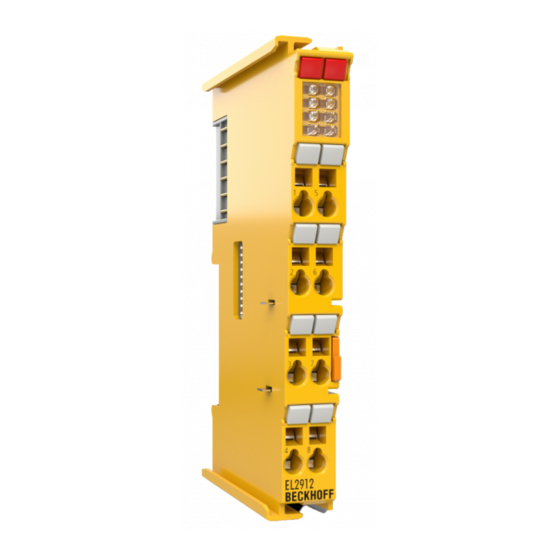
Product description Product description EL2912 - TwinSAFE terminal with two fail-safe outputs The EL2912 is a safe output terminal with two fail-safe outputs, each with 2 A (24 V The EL2912 meets the requirements of the following standards: • EN 61508:2010 (SIL 3) • EN 62061:2005/A2:2015 (SIL CL 3) •... -
Page 14: Intended Use
TwinSAFE components may only be used for the purposes described below! The TwinSAFE Terminals expand the application area of Beckhoff Bus Terminal system with functions that enable them to be used for machine safety applications. The TwinSAFE Terminals are designed for machine safety functions and directly associated industrial automation tasks. - Page 15 Product description CAUTION Follow the machinery directive! The TwinSAFE components may only be used in machines as defined in the machinery directive. CAUTION Ensure traceability! The buyer has to ensure the traceability of the device via the serial number. EL2912 Version: 1.0.0...
-
Page 16: Technical Data
Product description Technical data Product designation EL2912 Number of outputs Status display 4 (one green and one red LED for each output) Fault response time ≤ watchdog times Output current per channel max. 2 A (at 24 V Actuators When selecting actuators please ensure that the EL2912 test pulses do not lead to actuator switching. -
Page 17: Safety Parameters
Product description Derating table for altitudes above 2000 m The derating table (table 8) from the IEC 61131-2:2017 standard can be referred to for the use of the TwinSAFE components above the specified maximum altitude. Altitude in m Derating factor for the temperature 0 to 2000 3000 4000... -
Page 18: Safe Output
Product description Safe output The safe outputs are implemented as a single channel per module. It is essential to pay attention to the following note if two or more outputs run in a common sheathed cable. DANGER Clocked signals inside a sheathed cable If clocked signals from different modules are used inside a single sheathed cable, then a module error such as a cross-circuit or external power supply must lead to the switch-off of all of these modules. -
Page 19: Using The Integrated Twinsafe Logic Functions
Safety Editor and select the EL2912 as the target system. Further information on creating a project can be found in the EL6910 documentation and the description of the function blocks under http:// www.beckhoff.de/english/download/twinsafe.htm. In order to be able to use the EL2912 again as a safe TwinSAFE I/O slave, please delete the logic, the mapping and the parameter data on the EtherCAT Terminal and switch the voltage off and on again. - Page 20 Product description Process image size max. 1486 bytes per data direction (max. memory size 0x1E00 for 3 buffers, i.e. with identical input and output process data sizes the maximum size is 1280 bytes per data direction. Only even-numbered start addresses are possible, therefore padding bytes may have to be included) TwinSAFE connections maximum 212...
-
Page 21: Operation
Operation Operation Environmental conditions Please ensure that the TwinSAFE components are only transported, stored and operated under the specified conditions (see technical data)! WARNING Risk of injury! The TwinSAFE components must not be used under the following operating conditions. • under the influence of ionizing radiation (that exceeds the level of the natural environmental radiation) •... -
Page 22: Fig. 7 Spring Contacts Of Beckhoff I/O Components
• Each bus station must be terminated on the right side with the EL9011 or EL9012 end cap to ensure the protection class and ESD protection. Fig. 7: Spring contacts of Beckhoff I/O components 4.2.3.2 Control cabinet / terminal box The TwinSAFE terminals must be installed in a control cabinet or terminal box with IP54 protection class according to IEC 60529 as a minimum. -
Page 23: Fig. 8 Installation Position And Minimum Distances
Operation Fig. 8: Installation position and minimum distances In order to ensure optimum convection cooling, the distances to neighboring devices and to control cabinet walls must not be smaller than those shown in the diagram. 4.2.3.4 Temperature measurement The temperature measurement consists of an EK1100 EtherCAT Coupler, to which EtherCAT Terminals are attached, based on the typical distribution of digital and analog signal types at a machine. -
Page 24: Fig. 9 Thermally Unfavorable Arrangement Of The Twinsafe Terminals
Operation EL69x0 The EL69x0 emits a relatively high amount of waste heat, since it has a high internal clock rate and high logic performance. EL2904/EL291x The EL2904/EL291x emits a relatively high amount of waste heat due to the potentially high output current of the connected actuators. -
Page 25: Fig. 10 Thermally Favorable Arrangement Of The Twinsafe Terminals
Operation Fig. 10: Thermally favorable arrangement of the TwinSAFE terminals EL2912 Version: 1.0.0... -
Page 26: Fig. 11 Installation On The Mounting Rail
Operation 4.2.3.6 Installation on mounting rails WARNING Risk of electric shock and damage of device! Bring the bus terminal system into a safe, powered down state before starting installation, disassembly or wiring of the Bus Terminals! Mounting Fig. 11: Installation on the mounting rail The Bus Couplers and Bus Terminals are attached to commercially available 35 mm mounting rails (DIN rail according to EN 60715) by applying slight pressure: 1. -
Page 27: Electrical Installation
Operation Disassembly Fig. 12: Removal from mounting rail Each terminal is secured by a lock on the mounting rail, which must be released for disassembly: 1. Pull down the terminal at its orange-colored straps from the mounting rail by approx. 1 cm. The rail locking of this terminal is automatically released, and you can now pull the terminal out of the Bus Ter- minal block with little effort. -
Page 28: Fig. 13 Connection Of A Cable To A Terminal Point
Operation 4.2.4.2 Overvoltage protection If protection against overvoltage is necessary in your plant, provide a surge filter for the voltage supply to the Bus Terminal blocks and the TwinSAFE terminals. 4.2.4.3 Wiring Fig. 13: Connection of a cable to a terminal point Up to eight terminal points enable the connection of solid or finely stranded cables to the Bus Terminal. -
Page 29: Fig. 14 El2912 - Connection
Operation 4.2.4.4 EL2912 connection Fig. 14: EL2912 - connection Terminal point Input / Output Signal Output1 Output 1 (+ 24 V GND U Output2 Output 2 (+ 24 V GND1 Output 1 GND (directly connected to GND U GND U GND2 Output 2 GND (directly connected to GND U Power contact (top) Power contact (low) GND U... -
Page 30: Fig. 15 Max. Cable Length El2912
Operation 4.2.4.5 Signal cables Fig. 15: Max. cable length EL2912 When connecting a single actuator via its own continuous cabling (or via a sheathed cable), the maximum permitted cable length is 100 m. The use of contact points, connectors or small cable cross-sections in the wiring reduces the maximum expansion. - Page 31 Operation NOTE Route the signal cable separately The signal cable must be routed separately from potential sources of interference, such as motor supply ca- bles, 230 V power cables etc.! Interference caused by cables routed in parallel can influence the signal form of the test pulses and thus cause diagnostic messages (e.g.
-
Page 32: Configuration Of The Terminal In Twincat
See TwinCAT automation software documentation. 4.3.3 Adding an EL2912 An EL2912 is added in exactly the same way as any other Beckhoff EtherCAT Terminal. Open TwinSAFE Terminals item in the list and select the EL2912. Fig. 17: Adding an EL2912 Version: 1.0.0... -
Page 33: Address Settings On Twinsafe Terminals With 1023 Possible Addresses
Operation 4.3.4 Address settings on TwinSAFE terminals with 1023 possible addresses Fig. 18: Address settings on TwinSAFE terminals with 1023 possible addresses The TwinSAFE address of the terminal is set via the 10-way DIP switch on the left-hand side of the TwinSAFE terminal. -
Page 34: Alias Devices
Operation 4.3.5 Alias devices The communication between the safety logic and the I/O level is realized via an alias level. At this alias level (subnode Alias Devices) corresponding alias devices are created for all safe inputs and outputs, and also for standard signal types. -
Page 35: El2912 Parameters In Twincat
Operation Fig. 21: Creating alias devices by the user 4.3.6 EL2912 parameters in TwinCAT After creating the alias device, it can be parameterized according to the user specifications. The FSoE address is set under the Linking tab, and the link to the physical device is created. Fig. 22: Linking tab of the alias device EL2912 Version: 1.0.0... -
Page 36: Fig. 23 Connection Tab Of The Alias Device
Operation Under the Connection tab you can make further settings, e.g. the mapping of the info data or the behavior in case of a module error. Fig. 23: Connection tab of the alias device The Safety Parameters tab contains the parameters of the EL2911 to be set. The output is parameterized via parameter 0x8000. -
Page 37: El2912 Process Image
Operation 4.3.7 EL2912 process image The process image of the EL2912 consists of 6 bytes process data in the input and 6 bytes process data in the output. Fig. 25: EL2912 process image The assignment of the individual signals in the safe data is listed in the following table. Name Process Bit position Description... -
Page 38: Fig. 27 Worst Case Response Time
Operation Definition Description Response time of the sensor, until the signal is made available at the interface. Typically Sensor provided by the sensor manufacturer. Response time of the safe input, e.g. EL1904 or EP1908. This time can be found in the Input technical data. -
Page 39: Diagnostics
Operation Diagnostics 4.5.1 Status LEDs Fig. 28: EL2912 - Status and diagnostic LEDs Color Description Output 1 green Status and error display for the respective output Error 1 LED lights up: Output/error is set Output 2 green LED not lit: Output is not set or there is no error Error 2 4.5.2 Diagnostic LEDs... -
Page 40: Flash Code Display
Operation Logic error codes of LED Diag 2 (if LED Diag 1 is lit) Flashing Description Code Function block error in one of the TwinSAFE groups Communication error in one of the TwinSAFE groups Error combination: Function block and communication General error in one of the TwinSAFE groups Error combination: General and function block Error combination: General and communication Error combination: General, function block and communication... - Page 41 Operation Index Name Meaning Flags Default F984:01 Voltage C2 Voltage µC2 F984:02 Temperature C1 Temperature µC1 F984:03 Firmware CRC C1 CRC of the firmware on µC1 F984:04 Vendor data CRC C1 CRC of the vendor data on µC1 Index F985 : Device Info Data C2 CoE object F985 currently displays internal temperature and voltage values for the TwinSAFE component.
-
Page 42: Cycle Time Of The Safety Project
Operation Index Value Description F100:01 0: OFFLINE In the OFFLINE state no TwinSAFE logic program is loaded. No TwinSAFE groups and no TwinSAFE connections are processed. 1: RUN In the RUN state all TwinSAFE groups and all TwinSAFE connections configured in the TwinSAFE logic program are processed. -
Page 43: Diagnosis History
Operation Index FEA0 : CTRL Diag Data Index Name Meaning Flags Default FEA0:09 Actual Safety Control Current execution time of the TwinSAFE logic with a Task Execution Time logic state of 1 (RUN) Cycle time = 1.25 * value (average value of 64 cycles) FEA0:0A Min Safety Control Minimum execution time of the TwinSAFE logic with a Task Execution Time... - Page 44 Operation Index 10F3 Diagnosis History Index (hex) Name Meaning Data type Flags Default 10F3:0 Diagnosis History 10F3:01 Maximum Maximum number of stored messages. A UINT8 0x40 (64 Messages maximum of 64 messages can be stored. After that the respective oldest messages are overwritten.
-
Page 45: Fig. 30 Esi/Xml Message Text
Operation Dynamic parameters in the diagnosis messages Type Data type Description Flags parameter 1 UINT16 Describes the type of parameter 1 Bit 12…15 = 0 Bit 0…11 = data type of parameter 1 0x0001 - BOOLEAN 0x0002 - INT8 0x0003 - INT16 0x0004 - INT32 0x0005 - UINT8 0x0006 - UINT16... -
Page 46: Diag History Tab
Operation 4.5.7 Diag History tab All errors occurring within the TwinSAFE components are stored in their diag history. The diag history can be viewed by selecting the corresponding TwinSAFE component in the I/O tree structure and then selecting the Diag History tab. Use the Update History button to fetch the current data from the TwinSAFE component. Errors within the logic, the function blocks, the connections or the component itself are stored with a corresponding time stamp. -
Page 47: Maintenance
Operation Advanced Settings Setting Description Message Types • disable Info Messages with the Info status are not saved in the diag history • disable Warnings Messages with the Warning status are not saved in the diag history • disable Errors Messages with the Error status are not saved in the diag history Emergency In addition to saving the message in the diag history, an emergency object... -
Page 48: Service Life
Disposal In order to dispose of the device, it must be removed. In accordance with the WEEE Directive 2012/19/EU, Beckhoff takes back old devices and accessories in Germany for proper disposal. Transport costs will be borne by the sender. Return the old devices with the note "for disposal" to: Beckhoff Automation GmbH &... -
Page 49: Firmware Update Of Twinsafe Products
TwinSAFE component is deleted and replaced by a new version. The latest firmware can be downloaded from the Beckhoff website or requested from Beckhoff Support. The versions are available in an encrypted form and can only be loaded onto the matching TwinSAFE product. -
Page 50: Fig. 35 Firmware Update Of Twinsafe Products - Part 1
Operation Performing the firmware update Click the button (1) in the TwinCAT system to enter Config mode. Confirm the query with OK (2). After that a further window appears which must be confirmed with Yes (Ja) (3). Deactivate the "Free Run" with No (Nein) (4). -
Page 51: Fig. 36 Firmware Update Of Twinsafe Products - Part 2
Operation Fig. 36: Firmware update of TwinSAFE products - Part 2 In the place where you have stored the desired firmware version, select the firmware file (9) and click "Open" (10). Confirm the window that then opens with "OK" (11); the firmware update is then performed. After successful completion you must click OK (12) in the concluding "Function Succeeded"... -
Page 52: Appendix
Beckhoff's branch offices and representatives Please contact your Beckhoff branch office or representative for local support and service on Beckhoff products! The addresses of Beckhoff's branch offices and representatives round the world can be found on her internet pages: http://www.beckhoff.com You will also find further documentation for Beckhoff components there. -
Page 53: Certificates
Appendix Certificates EL2912 Version: 1.0.0... - Page 54 EL2912 - TwinSAFE terminal with two fail-safe outputs .............. Fig. 5 EL2912 - Dimensions ........................Fig. 6 Delete project data........................Fig. 7 Spring contacts of Beckhoff I/O components................Fig. 8 Installation position and minimum distances ................Fig. 9 Thermally unfavorable arrangement of the TwinSAFE terminals ..........Fig. 10 Thermally favorable arrangement of the TwinSAFE terminals ............
Need help?
Do you have a question about the TwinSAFE EL2912 and is the answer not in the manual?
Questions and answers