Beckhoff EL1904 Operating Instructions Manual
Twinsafe terminal with 4 digital fail-safe inputs
Hide thumbs
Also See for EL1904:
- Operating instructions manual (46 pages) ,
- Operating instructions manual (67 pages)

Related Manuals for Beckhoff EL1904


Summary of Contents for Beckhoff EL1904
- Page 1 Operating Instructions | EN EL1904 TwinSAFE Terminal with 4 digital fail-safe inputs 2023-03-06 | Version: 3.0.0...
-
Page 3: Table Of Contents
The I/O construction kit is extended safely .............. 17 3.2.2 Safety concept ......................... 17 3.2.3 EL1904, EL2904 - Bus Terminals with 4 fail-safe inputs or outputs......... 18 3.2.4 EL6900 - TwinSAFE logic terminal .................. 18 3.2.5 The fail-safe principle (Fail Stop) .................. 18 4 Product description .......................... - Page 4 Inserting a Bus Coupler.................... 39 5.4.2 Inserting a Bus Terminal .................... 39 5.4.3 Inserting an EL1904 ...................... 39 5.4.4 Address settings on TwinSAFE terminals with 65535 possible addresses...... 41 5.4.5 Entering a TwinSAFE address and parameters in the System Manager...... 42 Diagnostics............................
-
Page 5: Notes On The Documentation
Notes on the documentation Disclaimer Beckhoff products are subject to continuous further development. We reserve the right to revise the operating instructions at any time and without prior announcement. No claims for the modification of products that have already been supplied may be made on the basis of the data, diagrams and descriptions in these operating instructions. -
Page 6: Limitation Of Liability
Modifications and changes to the hardware and/or software configuration that go beyond the documented options are prohibited and nullify the liability of Beckhoff Automation GmbH & Co. KG. The following is excluded from the liability: •... -
Page 7: Documentation Issue Status
• Description of date code extended 1.3.1 • Document origin added 1.3.0 • Clock output currents in the technical data amended • Block diagram for EL1904 added 1.2.1 • Reference to EN 60068-2-29 removed 1.2.0 • ATEX notes amended • Installation position / minimum distances extended •... -
Page 8: Staff Qualification
Product features Only the product properties specified in the current operating instructions are valid. Further information given on the product pages of the Beckhoff homepage, in emails or in other publications is not authoritative. Staff qualification These operating instructions are intended exclusively for trained specialists in control technology and automation with the relevant knowledge. -
Page 9: Safety And Instruction
Notes are used for important information on the product. The possible consequences of failure to observe these include: • Malfunctions of the product • Damage to the product • Damage to the environment Information This sign indicates information, tips and notes for dealing with the product or the software. EL1904 Version: 3.0.0... -
Page 10: Beckhoff Support And Service
The employees support you in the programming and commissioning of sophisticated automation systems. Hotline: +49 5246/963-157 E-mail: support@beckhoff.com Web: www.beckhoff.com/support Training Training in Germany takes place in our training center at the Beckhoff headquarters in Verl, at subsidiaries or, by arrangement, at the customer's premises. Hotline: +49 5246/963-5000 E-mail: training@beckhoff.com Web: www.beckhoff.com/training... -
Page 11: For Your Safety
Products marked with a crossed-out waste bin must not be disposed of with domestic waste. The device is considered waste electrical and electronic equipment when it is disposed of. Observe the national regulations for the disposal of waste electrical and electronic equipment. EL1904 Version: 3.0.0... -
Page 12: Safety Image Signs
For your safety Safety image signs On Beckhoff products you will find attached or lasered safety pictograms, which vary depending on the product. They serve to serve to ensure safety for people and to prevent damage to the products. Safety pictograms must not be removed and must be legible for the user. -
Page 13: General Safety Instructions
De-energize and switch off components before working on them Check all safety-relevant equipment for functionality before working on the TwinSAFE component. Secure the working environment. Secure the machine or plant against being inadvertently started up. Observe the chapter Decommissioning [} 51]. EL1904 Version: 3.0.0... -
Page 14: System Description
System description The Beckhoff Bus Terminal system The Beckhoff Bus Terminal system is used for decentralized connection of sensors and actuators to a control system. The Beckhoff Bus Terminal system components are mainly used in industrial automation and building management applications. In its minimum configuration, a bus station consists of a Bus Coupler or a Bus Terminal Controller and Bus Terminals connected to it. -
Page 15: Bus Coupler
Fig. 2: Bus Coupler (EtherCAT) Connection technology Bus Coupler Wiring spring-loaded system Connection cross-section 0.08 mm² ... 2.5 mm², stranded wire, solid wire Fieldbus connection depending on fieldbus Power contacts 3 spring contacts Current load 10 A Rated voltage 24 V EL1904 Version: 3.0.0... -
Page 16: Bus Terminals
The power feed terminals play no part in the control of the terminals, and can be inserted at any locations within the terminal strip. Version: 3.0.0 EL1904... -
Page 17: Twinsafe
3.2.1 The I/O construction kit is extended safely With the TwinSAFE Terminals, Beckhoff offers the option of simply expanding the proven Bus Terminal system, and to transfer the complete cabling for the safety circuit into the already existing fieldbus cable. -
Page 18: El1904, El2904 - Bus Terminals With 4 Fail-Safe Inputs Or Outputs
EL1904, EL2904 - Bus Terminals with 4 fail-safe inputs or outputs The EL1904 and EL2904 Bus Terminals enable connection of common safety sensors and actuators. They are operated with the EL6900 TwinSAFE logic terminal. The TwinSAFE logic terminal is the link unit between the TwinSAFE input and output terminals. -
Page 19: Product Description
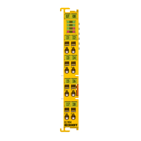
Product description EL1904 – TwinSAFE terminal with 4 digital fail-safe inputs The EL1904 is a digital input terminal for encoder with potential-free contacts for 24 V . The Bus Terminal has 4 fail-safe inputs. With two-channel connection, the EL1904 meets the requirements of IEC 61508:2010 SIL 3, EN ISO 13849-1:2015 (Cat 4, PL e), NRTL, UL508, UL1998 and UL991. -
Page 20: Intended Use
The buyer has to ensure the traceability of the device via the serial number. WARNING Commissioning test Before the EL1904/EL2904 can be used for the safety task, the user must carry out a commissioning test so that sensor and actuator wiring errors can be ruled out. CAUTION Use ferrules with plastic collars When using fine-wire cables for signal connections, use ferrules with plastic collars. - Page 21 EN 60529, so that the requirement for degree of pollution 3 according to EN 60664-1 can be reduced to level 2. • The TwinSAFE components must be supplied by a SELV/PELV power supply unit with a maximum voltage of U ≤ 36 V EL1904 Version: 3.0.0...
-
Page 22: Technical Data
Output current of the clock outputs typically 10 mA, max. 15 mA Input process image 6 bytes Output process image 6 bytes EL1904 supply voltage (PELV) 24 V (–15% / +20%) (A 10 A fuse should be provided for the potential group) Protection class III (by using a SELV/PELV power supply unit) Overvoltage category Signal voltage "0"... -
Page 23: Safety Parameters
Performance level PL e Category Element classification Type B 1. Special proof tests are not required during the entire service life of the EL1904 EtherCAT terminal. 2. Classification according to IEC 61508-2:2010 (chapter 7.4.4.1.2 and 7.4.4.1.3) EL1904 Version: 3.0.0... -
Page 24: Characteristic Curve Of The Inputs
Product description The EL1904 EtherCAT Terminal can be used for safety-related applications within the meaning of IEC 61508:2010 up to SIL3 and EN ISO 13849-1:2015 up to PL e (Cat4). For the calculation or estimation of the MTTF value from the PFH value, further information can be found in the TwinSAFE Application Guide or in ISO 13849-1:2015 Table K.1. -
Page 25: Dimensions
Depth: 68 mm Block diagram of the EL1904 Fig. 7: Block diagram of the EL1904 The block diagram shows the basic configuration of a channel in the EL1904. The part with a red border is present four times in the terminal. EL1904... -
Page 26: Operation
Please ensure that the digital TwinSAFE components are only transported and stored under the specified environmental conditions (see technical data). 5.2.3 Mechanical installation WARNING Risk of injury! Bring the bus system into a safe, de-energized state before starting installation, disassembly or wiring of the devices! Version: 3.0.0 EL1904... -
Page 27: Fig. 8 Installation Position And Minimum Distances
Fig. 8: Installation position and minimum distances In order to ensure optimum convection cooling, the distances to neighboring devices and to control cabinet walls must not be smaller than those shown in the diagram. EL1904 Version: 3.0.0... -
Page 28: Fig. 9 Example Configuration For Temperature Measurement
The key parameter is always the maximum permitted internally measured temperature of 95°C, above which the TwinSAFE terminals switch to safe state and report an error. The internal temperature can be read from the TwinSAFE components via CoE (see chapter Diagnose). Version: 3.0.0 EL1904... -
Page 29: Fig. 10 Installation On The Mounting Rail
When installing the components, make sure that the locking mechanism doesn't come into conflict with the fixing bolts of the mounting rail. For fastening mounting rails with a height of 7.5 mm under the terminals and couplers, use flat fastening components such as countersunk head screws or blind rivets. EL1904 Version: 3.0.0... -
Page 30: Electrical Installation
(e.g. analog Bus Terminals or digital 4-channel Bus Terminals) do not or not fully loop through the power contacts. Potential supply terminals (EL91xx, EL92xx) interrupt the power contacts and thus represent the start of a new supply rail. Version: 3.0.0 EL1904... -
Page 31: Fig. 12 Pe Power Contact
The PE power contact must not be used for other potentials! 5.2.4.2 Overvoltage protection If protection against overvoltage is necessary in your plant, provide a surge filter for the voltage supply to the Bus Terminal blocks and the TwinSAFE terminals. EL1904 Version: 3.0.0... -
Page 32: Fig. 13 Connection Of A Cable To A Terminal Point
See the following table for the suitable wire size width. Wire size width (single core wires) 0.08 ... 2.5 mm Wire size width (fine-wire conductors) 0.08 ... 2.5 mm Wire size width (conductors with a wire end sleeve) 0.14 ... 1.5 mm Wire stripping length 8 ... 9 mm Version: 3.0.0 EL1904... -
Page 33: Fig. 14 El1904 Pin Assignment
Operation 5.2.4.4 EL1904 pin assignment Fig. 14: EL1904 pin assignment Terminal point Input Signal Input 1+ Input 1- Input 3+ Input 3- Input 2+ Input 2- Input 4+ Input 4- Configurable inputs The inputs 1 to 4 can be occupied as you want with normally closed contacts or normally open contacts. -
Page 34: Fig. 15 Permitted Cable Length
When connecting a single switching contact via its own continuous cabling (or via a non-metallic sheathed cable), the maximum permitted cable length is 100 m. The use of contact points, connectors or additional switching contacts in the cabling reduces the maximum propagation. Cable routing Fig. 16: Cable routing Version: 3.0.0 EL1904... -
Page 35: Fig. 17 Typical Course Of Test Pulses Of The Inputs
The times between the test pulses of different channels vary, thus allowing better diagnostic detection. Fig. 17: Typical course of test pulses of the inputs If self-testing sensors are to be used on the safe inputs, please refer to chapter Configuration for light barriers, light grids, light curtains etc [} 44]. EL1904 Version: 3.0.0... -
Page 36: Twinsafe Reaction Times
Response time of the sensor, until the signal is made available at the interface. Typically Sensor provided by the sensor manufacturer. Response time of the safe input, e.g. EL1904 or EP1908. This time can be found in the Input technical data. In the case of the EL1904 it is 4 ms. -
Page 37: Tested El1904 Devices
5.2.6 Tested EL1904 devices The following list contains devices that were tested together with the EL1904 TwinSAFE terminal. The results only apply for the current device hardware version at the time of testing. The tests were carried out in a laboratory environment. Modifications of these products cannot be considered here. If you are unsure please test the hardware together with the TwinSAFE terminal. -
Page 38: Operation In Potentially Explosive Atmospheres (Atex)
• EN 60079-15: 2005 5.3.2 Identification Beckhoff fieldbus components that are certified for use in potentially explosive atmospheres bear one of the following markings: II 3 G Ex nA IIC T4 Gc KEMA 10ATEX0075 X Ta: 0 … 55 °C II 3 G Ex nA nC IIC T4 Gc KEMA 10ATEX0075 X Ta: 0 …... -
Page 39: Date Code And Serial Number
Inserting a Bus Terminal See TwinCAT automation software documentation. 5.4.3 Inserting an EL1904 An EL1904 is inserted in the same way as any other Beckhoff Bus Terminal. In the list open Safety Terminals (ELx9xx) and select the EL1904. EL1904 Version: 3.0.0... -
Page 40: Fig. 20 Inserting An El1904
Operation Fig. 20: Inserting an EL1904 Version: 3.0.0 EL1904... -
Page 41: Address Settings On Twinsafe Terminals With 65535 Possible Addresses
Fig. 21: Address settings on TwinSAFE terminals with 65535 possible addresses Set the TwinSAFE address for the terminal using the two dip switches (with 8 setting options) on the left- hand side of the EL1904 TwinSAFE terminal. TwinSAFE addresses between 1 and 65535 are available. DIP switches... -
Page 42: Entering A Twinsafe Address And Parameters In The System Manager
The TwinSAFE address set at the DIP switch must also be entered in tab FSoE (under FSoE address) under the EL1904. Fig. 22: Entering the FSoE address The EL1904 parameters are set under the respective TwinSAFE connection in the Connection and Parameter tabs. Version: 3.0.0... -
Page 43: Fig. 23 Setting The Connection Of The Twinsafe Connection
(Standstill monitoring is not supported) Sensor test The clock signal for connection Input1+ true / false channel 1 active is checked at connection Input1-. Sensor test The clock signal for connection Input2+ true / false channel 2 active is checked at connection Input2-. EL1904 Version: 3.0.0... -
Page 44: Fig. 25 Maximum Permissible Sensor Self-Test Duration Of 350 Μs
Only sensors with self-testing outputs and a maximum sensor self-test duration of 350 µs may be connected to the EL1904 (see illustration below). Fig. 25: Maximum permissible sensor self-test duration of 350 µs Parameter To connect these sensors please set the following parameters for the EL1904 in the TwinCAT System Manager: Version: 3.0.0 EL1904... - Page 45 The EL1904 also supports direct connection of safety switching mats. Parameter To connect these switching mats please set the following parameters for the EL1904 in the TwinCAT System Manager: Connect the two sensor signals either to channels 1 and 2 or channels 3 and 4 and activate short cut channel x/y is no module fault for the two inputs used under parameter Logic for channel x and y.
-
Page 46: Diagnostics
If the Diag 3 LED is lit, the Diag 4 LED indicates internal terminal errors. Flashing Codes In the case of such an error, the Diag 4 LED on the EL1904 displays flashing codes that describe the error in more detail. -
Page 47: Diagnostic Objects
If another flashing code is displayed, this means that there is an internal terminal error that has stopped the terminal. In this case the terminal must be checked by Beckhoff Automation GmbH & Co. KG. Note the flashing codes and return the terminal Note the flashing code displayed and include this information with the terminal when you return it. - Page 48 Error at input 2 Error at input 3 Error at input 4 Differing diagnostic messages possible Due to the variable order or execution of the test series, diagnostic messages differing from those given in the table above are possible. Version: 3.0.0 EL1904...
-
Page 49: Service Life
YY: Year of manufacture Year: 2011 SW: Software version Software version: 05 HW: Hardware version Hardware version: 00 In addition the TwinSAFE terminals bear a unique serial number. 00000000 17110500 Fig. 26: Unique serial number of a TwinSAFE terminal EL1904 Version: 3.0.0... -
Page 50: Maintenance And Cleaning
Maintenance and cleaning Cleaning by the manufacturer only Do not operate the TwinSAFE component if it is impermissibly dirty according to protection class IP20. Send impermissibly dirty TwinSAFE components to the manufacturer for cleaning. TwinSAFE components are basically maintenance-free. Version: 3.0.0 EL1904... -
Page 51: Decommissioning
In accordance with the WEEE-2012/19/EU directives, you can return used devices and accessories for professional disposal. The transport costs are borne by the sender. Send the used devices with the note "For disposal" to: Beckhoff Automation GmbH & Co. KG Gebäude „Service“ Stahlstraße 31... -
Page 52: Appendix
If there is customer specific data saved on the product, it cannot be ensured that this data might not be restored through for example forensic measures, even after the data is deleted through the provided tool chain. If this data is confidential, the scrapping of the product after usage is recommended to protect this data. Version: 3.0.0 EL1904... -
Page 53: Focus Of Certificates
The current certificates of all TwinSAFE components with the underlying standards and directives can be found at https://www.beckhoff.com/en-en/support/download-finder/certificates-approvals/. If the document refers only to the first four figures of a product (ELxxxx), the certificate is valid for all available variants of the component (ELxxxx-abcd). -
Page 54: Certificates
Appendix Certificates Fig. 27: EL1904 EC Declaration of Conformity Version: 3.0.0 EL1904... - Page 55 Fig. 2 Bus Coupler (EtherCAT) ......................Fig. 3 TwinSAFE Terminals (EtherCAT) ....................Fig. 4 EL1904 – TwinSAFE terminal with 4 digital fail-safe inputs ............Fig. 5 Characteristic curve of the inputs....................Fig. 6 Dimensions of the EL1904 ......................Fig. 7 Block diagram of the EL1904 .......................
- Page 57 More Information: www.beckhoff.com/EL1904 Beckhoff Automation GmbH & Co. KG Hülshorstweg 20 33415 Verl Germany Phone: +49 5246 9630 info@beckhoff.com www.beckhoff.com...
Need help?
Do you have a question about the EL1904 and is the answer not in the manual?
Questions and answers