Table of Contents
Advertisement
Advertisement
Table of Contents

Related Manuals for Honeywell HVAC232 Series


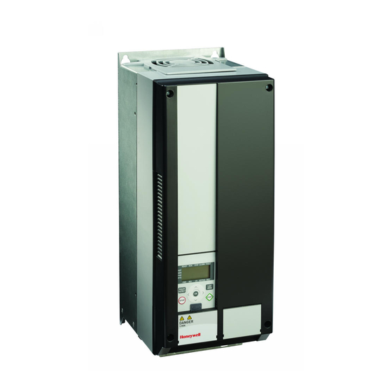
Summary of Contents for Honeywell HVAC232 Series
- Page 1 HVAC232/402 APPLICATION MANUAL 27-652_ENG06...
-
Page 2: Table Of Contents
Content 0 DOCUMENT HYSTORY .......................... 5 1 SAFETY ................................ 6 Warnings .................................................... 7 Safety instructions ................................................ 8 Earthing and earth fault protection ......................................... 9 Before running the motor ............................................. 10 2 RECEIPT OF DELIVERY .......................... 10 Storage .................................................... 10 Maintenance .................................................. 10 Warranty ... - Page 3 5 FAULT TRACING ............................ 35 6 HVAC232/402 APPLICATION INTERFACE .................. 41 Introduction .................................................. 41 Control I/O .................................................... 42 7 CONTROL PANEL ............................ 44 General .................................................... 44 Display .................................................... 44 Keypad .................................................... 46 8 NAVIGATION ON THE HVAC232/402 CONTROL PANEL .............. 47 Main menu ...
- Page 4 10 Parameter description .......................... 96 10.1 Motor settings (Control panel: Menu PAR P1) .................................. 96 10.2 Start / stop setup (Control panel: Menu PAR P2) .................................. 101 10.3 Frequency references (Control panel: Menu PAR P3) ................................ 112 ...
-
Page 5: Document Hystory
DOCUMENT HYSTORY Version Date Modifications ENG06 2019-08-07 Table 54 : Modbus: Input process data: ID2003 new Name "Frequency reference" and new Type "0…10'000" Application manual HVAC232/402 | Document 27-652 | Issue ENG06 | 2019-08-07... -
Page 6: Safety
SAFETY Please read the information included in cautions and warnings carefully: CAUTION ONLY A COMPETENT ELECTRICIAN IS ALLOWED TO CARRY OUT THE ELECTRICAL INSTALLATION! This manual contains clearly marked cautions and warnings which are intended for your personal safety and to avoid any unintentional damage to the product or connected appliances. -
Page 7: Warnings
Warnings WARNING WARNING The components of the power unit of the frequency converter If the frequency converter is used as a part of a machine, are live when HVAC232/402 is connected to mains. Coming the machine manufacturer is responsible for providing the into contact with this voltage is extremely dangerous and may machine with a main switch (EN 60204-1). -
Page 8: Safety Instructions
Safety instructions CAUTION CAUTION The HVAC232/402 frequency converter has been designed for Prior to measurements on the motor or the motor cable, fixed installations only. disconnect the motor cable from the frequency converter. CAUTION CAUTION Do not perform any measurements when the frequency Do not open the cover of HVAC232/402. -
Page 9: Earthing And Earth Fault Protection
Earthing and earth fault protection The Smart HVAC232/402 frequency converter must always be earthed with an earthing conductor connected to the earthing terminal. See figure below: MCR36497 Fig. 2. MI4 MCR36496 Fig. 1. MI1 - MI3 MCR36498 Fig. 3. MI5 1. -
Page 10: Before Running The Motor
Before running the motor Maintenance In normal operating conditions, HVAC232/402 frequency converters are Checklist: maintenance- free. However, regular maintenance is recommended to ensure a trouble-free operating and along lifetime of the drive. We recom- Before starting the motor, check that the motor is mounted properly ... -
Page 11: Warranty
INSTALLATION Capacitor recharge After a longer storage time the capacitors need to be recharge in order to avoid capacitor damage. Possible high leakage current through the capac- Mechanical installation itors must be limited. The best way to achieve this is to use a DC-power supply with adjustable current limit. - Page 12 =M 6 =M 6 M36502 Fig. 6. DIN-rail mounting, MI1 - MI3 BACK BACK RESET RESET M36501 Fig. 5. Screw mounting, MI4 - MI5 NOTE: See the mounting dimensions on the back of the drive. BACK RESET M36503 Fig. 7. Flange mounting, MI4 - MI5 Application manual HVAC232/402 | Document 27-652 | Issue ENG06 | 2019-08-07...
- Page 13 14-1/2 (370) Ø 1/4 (7) 1-3/32 DRIVE OUTLINE 13/64 (6) 1-3/32 (29) 51/64 (16) (29) (20) OPENING OUTLINE 6-1/2 (166) 6-51/64 (153) 14-19/64 (362) (173) 7-13/32 (189) 14 (356) (379) 15-7/64 (384) (332) M36504 Fig. 8. Flange mounting cutout dimensions for MI4 [Unit: inches (mm)] Ø...
-
Page 14: Hvac232/402 Dimensions
HVAC232/402 dimensions D (D1) D (D1) W (W1) W (W1) Fig. 11. HVAC232/402 dimensions, Fig. 12. HVAC232/402 dimensions, MI1 - MI3 MI4 -MI5 Application manual HVAC232/402 | Document 27-652 | Issue ENG06 | 2019-08-07... - Page 15 Table 2. HVAC232/402 dimensions in inches (mm). Type 6.3 (160.1) 5.8 (147) 5.4 (137.3) 2.6 (65.5) 1.5 (37.8) .18 (4.5) 3.9 (98.5) .28 (7) 7.7 (195) 7.2 (183) 6.7 (170) 3.5 (90) 2.5 (62.5) .22(5.5) 4 (101.5) .28 (7) 10 (254.3) 9.6 (244) 9.0 (229.3) 3.9 (100)
- Page 16 Fig. 13. HVAC232/402 dimensions, Fig. 14. HVAC232/402 dimensions, MI2-3 - Display Location MI4-5 - Display Location Dimensions in Frame Dimensions in Frame inches (mm) inches (mm) .7 (17) .9 (22.3) 8 (205) 9.8 (248.5) 1.7 (44) 4 (102) 3.4 (87) 3.4 (87) Application manual HVAC232/402 | Document 27-652 | Issue ENG06 | 2019-08-07...
-
Page 17: Cooling
Cooling Enough free space shall be left above and below the frequency converter to ensure sufficient air circulation and cooling. You will find the required dimensions for free space in the table below. If several units are mounted above each other, the required free space equals C + D (see figure below). -
Page 18: Power Losses
Power losses If the operator wants to raise the switching frequency of the drive for some reason (typically e.g. in order to reduce the motor noise), this inevitably affects the power losses and cooling requirements, for different motor shaft power, operator can select the switching frequency according to the graphs below. - Page 19 MI1 - MI5 3P 400 V POWER LOSS Application manual HVAC232/402 | Document 27-652 | Issue ENG06 | 2019-08-07...
- Page 20 MI1 - MI5 3P 400 V POWER LOSS Application manual HVAC232/402 | Document 27-652 | Issue ENG06 | 2019-08-07...
-
Page 21: Emc Levels
EMC levels Category C4: The drives of this class do not provide EMC emission protec- EN61800-3 defines the division of frequency converters into four classes according to the level of electromagnetic disturbances emitted, the require- tion. These kinds of drives are mounted in enclosures. ments of a power system network and the installation environment (see be- low). -
Page 22: Changing The Emc Protection Class From C2 To C4
Changing the EMC protection class from C2 to C4 The EMC protection class of MI1-3 frequency converters can be changed from class C2 to class C4 by removing the EMC-capacitor disconnecting screw, see figure below. MI4 & 5 can also be changed by removing the EMC jumpers. NOTE: Do not attempt to change the EMC level back to class C2. -
Page 23: Cabling And Connections
Cabling and connections Power cabling NOTE: Tightening torque for power cables is 0.5 - 0.6 Nm. 3~ (230 V, 400 V) 1~ (230 V) Motor out 3~ (230 V, 400 V, 600 V) External brake resistor 3~ (230 V, 400 V, 600 V) 1~ (230V) 1~ (115V) Motor out L1 L2/N L3... - Page 24 3~ (380 V, 480 V) Control Cabling Motor out Attach the support AFTER installing the power cables BRAKE RESISTOR MAINS MOTOR Fig. 22. HVAC232/402 power connections, MI4 Attach this plate BEFORE 3~ (380 V, 480 V) installing the power cables Motor out BRAKE MAINS...
- Page 25 Attach the support AFTER installing the power cables Fig. 26. Open the lid, MI1 - MI3 Attach this plate BEFORE installing the power cables Fig. 25. Mount the PE-plate and API cable support, Fig. 27. Open the lid, MI4 - MI5 MI4 - MI5 Application manual HVAC232/402 | Document 27-652 | Issue ENG06 | 2019-08-07...
- Page 26 Allowed option boards in HVAC232/402 NOTE: When OPTB1, OPTB2 or OPTB4 are used in HVAC232/402, +24 VDC (±10 %, min. 300 mA) power should be supplied to Control cable tightening Terminal 6 (+24_out) and Terminal 3 (GND) in control board. torque: 0.4 Nm Table 6.
- Page 27 Optional board assembly structure: Application manual HVAC232/402 | Document 27-652 | Issue ENG06 | 2019-08-07...
-
Page 28: Screw Of Cables
Screw of cables 12 screws M4 × 8 10 screws M4 × 8 Fig. 30. MI1 screws Fig. 31. MI2 screws 14 Screws M4 × 9 10 screws M4 × 8 6 Screws M4 × 17 4 screws M4 × 10 Fig. - Page 29 Cable installation“ Consult the factory about faster fuses. on page 32. Honeywell offers recommendations also for aR (IEC 60269-4) The fuses function also as cable overload protection. The recommended and gS (IEC 60269-4) fuse ranges. fuse types are gG/gL (IEC 60269-1). The fuse voltage rating should be selected according to the supply network.
- Page 30 Table 9. Cable and fuse sizes for HVAC232/402, 208 - 240 V, 1~ Frame Power Fuse Mains cable Motor cable Terminal cable size (min/max) [kW] Cu [mm Cu [mm Main Earth Control Relay terminal terminal terminal terminal 0.25…0.55 2 × 1.5+1.5 3 ×...
-
Page 31: Stripping Lengths Of Motor And Mains Cables
Stripping lengths of motor and mains General cabling rules cables Before starting the installation, check that none of the components of the frequency converter is live. Place the motor cables sufficiently far from other cables: Earth conductor • Avoid placing the motor cables in long parallel lines with other cables. -
Page 32: Cable Installation
COMMISSIONING AND 3.10 Cable installation START-UP WIZARD The units are suitable for use on a circuit capable of delivering not more than 50,000 A symmetrical amperes. Motor overload protection provided at 110% of full load current. Before commissioning, read the warnings and in- structions listed in „1 SAFETY“... - Page 33 Perform test run without motor. Perform either Test A or Test B: A) Control from the I/O terminals: • Turn the Start/Stop switch to ON position. • Change the frequency reference (potentiometer). • Check the Monitoring Menu and make sure that the value of Output frequency changes according to the change of frequen- cy reference.
-
Page 34: Startup Wizard
Startup Wizard Honeywell HVAC232/402 runs the startup wizard at initial power-up and whenever the drive is reset to factory defaults. The Start-up wizard content is shown below. It always asks the basic param- eters (P1.1-P16.1). If you activate the fire mode parameters with P16.1, it will go through rest of the Fire mode parameters. -
Page 35: Fault Tracing
FAULT TRACING When a fatal fault is detected by the frequency converter control electron- The active fault can be reset by pressing BACK/RESET button when the ics, the drive will stop and the symbol FT and the fault code blinked on the API is in active fault menu level (FT XX), or pressing BACK/RESET button display are in the following format, e.g.: with long time (>... - Page 36 Fault code Fault name Possible cause Correcting actions Under voltage The DC-link voltage has gone below the internal In case of temporary supply voltage break reset the safety limit: fault and restart the frequency converter. • most probable cause: supply voltage is too low Check the supply voltage.
- Page 37 If installation is correct, contact the nearest Honeywell distributor. Slot fault The connection between optional board and API has Check board and slot. been broken. Contact the nearest Honeywell distributor. Application manual HVAC232/402 | Document 27-652 | Issue ENG06 | 2019-08-07...
- Page 38 Fault code Fault name Possible cause Correcting actions Wrong run fault (FWD/ Run forward and backward are high at the same time. Check I/O control signal 1 and I/O control signal 2. REV conflict) Motor identification fault Motor identification run has failed. Run command was removed before completion of identification run.
- Page 39 Table 12. Fault subcodes from power Table 13. Fault subcodes from control API F08 SubCode Fault F08 SubCode Fault Watchdog reset MPI CRC SW stack overflow. MPI2 CRC HW stack overflow HMI receive buffer overflow Misalignment MODBUS receive buffer overflow Illegal op Power source cannot be recognized PLL lost lock / Low CPU voltage...
- Page 40 Table 14. Fault subcodes F22 SubCode Fault DA_CN, Power down data counter error DA_PD, Power down data restore fail DA_FH, Fault history data error DA_PA, Restore parameter CRC error Reserved DA_PER_CN, Persist data counter error DA_PER_PD, Persist data restore fail Table 15.
-
Page 41: Hvac232/402 Application Interface
HVAC232/402 APPLICATION SPECIAL FEATURES: INTERFACE • Programmable Start/Stop and Reverse signal logic • Motor pre-heat • Reference scaling Introduction • DC-brake at start and stop • Programmable U / f curve There is only one version of Control Board available for the HVAC232/402 drive: •... -
Page 42: Control I/O
Control I/O Table 17. HVAC232/402 General purpose application default I/O configuration and connections for control board 1–10 kΩ Terminal Signal Factory preset Description 1 +10 Vref Ref. voltage out Maximum load 10 mA 2 AI1 Analogue signal in 1 Freq. reference 0 …... - Page 43 Table 18. DI Sink Type, remove jumper J500 and connect the wire using this table Terminal Signal Factory preset Description 3 GND I/O signal ground 6 24 Vout 24 V output for DI's ±20%, max. load 50 mA 7 DI_C Digital Input Common Digital Input Common for DI1-DI6 8 DI1...
-
Page 44: Control Panel
CONTROL PANEL General Display The panel is an irremovable part of the drive consisting of corresponding The display includes 14-segment and 7-segment blocks, arrowheads and control board; The overlay with display status on the cover and the button clear text unit symbols. The arrowheads, are directed on some information are in clarifications in the user language. - Page 45 Group 1 - 5; Drive status 1. Drive is ready to start(READY) 2. Drive is running(RUN) 3. Drive has stopped(STOP) 4. Alarm condition is active(ALARM) 5. Drive has stopped due to a fault(FAULT) Group 6 - 10; Control selections When API is operated by PC control, there are no arrowhead at I/O, KEYPAD and BUS.
-
Page 46: Keypad
Keypad The drive stops by pressing the keypad STOP button, regardless of the The keypad section of the control panel consists of 9 buttons (see „Fig. 37. selected control place when Par. 2.7 (Keypad stop button) is 1. If Par. 2.7 is HVAC232/402 Control panel“... -
Page 47: Navigation On The Hvac232/402 Control Panel
NAVIGATION ON THE HVAC232/402 CONTROL PANEL This chapter provides you with information on navigating the menus on HVAC232/402 and editing the values of the parameters. Main menu The menu structure of HVAC232/402 control software consists of a main menu and several submenus. Navigation in the main menu is shown below: Application manual HVAC232/402 | Document 27-652 | Issue ENG06 | 2019-08-07... - Page 48 Fig. 38. The main menu of HVAC232/402 REFERENCE R E A D Y R U N S T OP A L AR M FA U LT R E A D Y R U N S TO P A L AR M FA U LT MENU R E F...
-
Page 49: Reference Menu
Reference menu Move to the reference menu with the UP / DOWN button (see „Fig. 38. The main menu of HVAC232/402“ on page 48). The reference value can be changed with UP / DOWN button as shown in „Fig. 39. Reference menu dis- RE ADY R U N S T OP... -
Page 50: Monitoring Menu
Monitoring menu Monitoring values are actual values of measured signals as well as status of some control settings. It is visible in HVAC232/402 display, but it can not be edited. The monitoring values are listed in „Table 20. Monitoring values“ on RE ADY RU N S TOP ALARM... - Page 51 Table 20. Monitoring values Code Monitoring signal Unit Description V1.1 Output frequency Output frequency to motor V1.2 Frequency reference Frequency reference to motor control V1.3 Motor speed Calculated motor speed V1.4 Motor current Measured motor current V1.5 Motor torque Calculated actual / nominal torque of the motor V1.6 Motor shaft power Calculated actual / nominal power of the motor...
- Page 52 Table 20. Monitoring values Code Monitoring signal Unit Description V3.1 Drive status word Bit codes status of drive B0 = Ready B6 = RunEnable B1 = Run B7 = AlarmActive B2 = Reverse B12 = RunRequest B3 = Fault B13 = MotorRegulatorActive V3.2 Application status word Bit codes status of application:...
-
Page 53: Parameter Menu
Parameter menu In Parameter menu only the Quick setup parameter list is shown as default. The parameter can be changed as the Figure „Fig. 41. Parameter menu“ on By giving the value 0 to the parameter 17.2, it is possible to open other page 51. -
Page 54: System Menu
System menu SYS menu including fault submenu, field bus submenu and system parame- In active fault situation, FAULT arrow is blinking and the display is blinking ter submenu, and the display and operation of the system parameter sub- active fault menu item with fault code. If there are several active faults, you menu is similar to PAR menu or MON menu. -
Page 55: Standard Application Parameters
Standard application parameters On the next pages you can find the lists of parameters within the respective parameter groups. The parameter descriptions are given in „10 Parameter description“ à la page 96. Explanations: Code: Location indication on the keypad; Shows the operator the present Monitoring value number or Parameter number Parameter: Name of monitoring value or parameter Min:... -
Page 56: Quick Setup Parameters
Quick setup parameters (Virtual menu, shows when par. 16.2 Table 21. Quick setup parameters. Code Parameter Unit Default Note P1.1 Motor nominal voltage Varies P1.2 Motor nominal frequency 30,00 320,00 50,00/60,00 P1.3 Motor nominal speed 20000 1440/1720 P1.4 Motor nominal current 0,2 ×... - Page 57 Table 21. Quick setup parameters. Code Parameter Unit Default Note P3.5 Preset speed 2 P3.1 P3.2 15,00 P3.7 Preset speed 3 P3.1 P3.2 20,00 P4.2 Acceleration time 1 3000,0 P4.3 Declaration time 1 3000,0 P6.1 AI1 range P6.5 AI2 range (see the P6.1) P10.1 Prohibit 0,00 P3.2...
- Page 58 Table 21. Quick setup parameters. Code Parameter Unit Default Note 0 = AI1 P14.4 Feedback source selection Varies 1 = AI2 2 = ProcessDataIn1(0-100%) 3 = ProcessDataIn2(0-100%) 4 = ProcessDataIn3(0-100%) 5 = ProcessDataIn4(0-100%) 6 = AI2-AI1 7 = AIE1 8 = Temperature input 1 9 = Temperature input 2 10 = Temperature input 3 P14.5 Feedback value min...
- Page 59 Table 21. Quick setup parameters. Code Parameter Unit Default Note P18.2 Fire mode frequency select Varies 1617 Fire mode frequency preset NOTE! This parameter will be locked when fire mode is active. To change the parameter you have to disable fire mode.
- Page 60 Application manual HVAC232/402 | Document 27-652 | Issue ENG06 | 2019-08-07...
- Page 61 9.1.1 Motor settings (Control panel: Menu PAR -> P1) Table 22. Motor settings Code Parameter Unit Default Note P1.1 Motor nominal voltage Varies P1.2 Motor nominal frequency 30,00 320,00 50,00/60,00 P1.3 Motor nominal speed 20000 1440/1720 P1.4 Motor nominal current 0,2 ×...
- Page 62 Table 22. Motor settings Code Parameter Unit Default Note 0 = not active P1.17 Motor identification 1 = standstill identification ( need run command within 20 s to activate) 2 = ID with run P1.18 Rs voltage drop 0,00 100,00 0,00 Voltage drop over motor windings as % of Un at nominal current.
- Page 63 Table 22. Motor settings Code Parameter Unit Default Note P1.24 I/f start enable The I/f Start function is typically used with perma- nent magnet motors (PM) to start the motor with constant current control. This is useful with high power motors in which the resistance is low and the tuning of the U/f curve difficult.
- Page 64 Application manual HVAC232/402 | Document 27-652 | Issue ENG06 | 2019-08-07...
- Page 65 9.1.2 Start / stop setup (Control panel: Menu PAR Table 23. Start / stop setup. Code Parameter Unit Default Note 0 = I/O terminals P2.1 Remote Control Place 1 Selection 1 = Fieldbus 2 = Keypad 0 = Ramping P2.2 Start function 1 = Flying start...
- Page 66 9.1.3 Frequency references (Control panel: Menu PAR Table 24. Frequency references. Code Parameter Unit Default Note P3.1 Min frequency 0,001 P3.2 0,00 P3.2 Max frequency P3.1 320,00 50,00/60,00 1 = Preset speed 0 P3.3 Remote Control Place 1 Varies frequency reference selection 2 = Keypad 3 = Fieldbus...
- Page 67 Table 24. Frequency references. Code Parameter Unit Default Note P3.12 Remote Control Place 2 P3.1 Varies As parameter P3.3 frequency reference selection P3.13 Motor Hz/s Potentionmeter Ramp 0 = No reset P3.14 Motor Potentionmeter 1 = Reset if stopped 2 = Reset if powered down Reset NOTE: These parameters are shown, when P16.2 = 0.
- Page 68 9.1.4 Ramps and brakes setup (Control panel: Menu PAR Table 25. Ramps and brakes setup. Code Parameter Unit Default Note P4.1 Ramp S-shape 1 10,0 P4.2 Acceleration time 1 3000,0 P4.3 Deceleration time 1 3000,0 P4.4 Ramp S-shape 2 10,0 P4.5 Acceleration time 2...
- Page 69 Table 25. Ramps and brakes setup. Code Parameter Unit Default Note P4.18 External Brake : Close 0,00 P3.2 1,50 1540 Frequency limit in Reverse P4.19 External Brake : Open/Close 200,0 20,0 1585 Current limit Application manual HVAC232/402 | Document 27-652 | Issue ENG06 | 2019-08-07...
- Page 70 9.1.5 Digital inputs (Control panel: Menu PAR Table 26. Digital inputs. Code Parameter Unit Default Note 0 = Not used P5.1 I/O control signal 1 Varies 1 = DI1 2 = DI2 3 = DI3 4 = DI4 5 = DI5 6 = DI6 7 = DIE1 8 = DIE2...
- Page 71 Table 26. Digital inputs. Code Parameter Unit Default Note P5.13 Motor potentiometer down Varies P5.14 Remote control place 2 Varies P5.15 Remote control place freq Varies reference 2 P5.16 PID setpoint 2 Varies 1047 P5.17 Motor PreHeat ON Varies 1044 Application manual HVAC232/402 | Document 27-652 | Issue ENG06 | 2019-08-07...
- Page 72 9.1.6 Analogue inputs (Control panel: Menu PAR Table 27. Analogue inputs. Code Parameter Unit Default Note 0 = 0 - 100% P6.1 AI1 range 1 = 20% - 100% P6.2 AI1 Custom min –100,00 100,00 0,00 P6.3 AI1 Custom max –100,00 300,00 100,0...
- Page 73 9.1.7 Digital outputs (Control panel: Menu PAR P7) Table 28. Digital outputs. Code Parameter Unit Default Note P7.1 RO1 signal selection Varies 0 = Not used 1 = Ready 2 = Run 3 = Fault 4 = Fault Inverted 5 = Warning 6 = Reversed 7 = At Speed...
- Page 74 Table 28. Digital outputs. Code Parameter Unit Default Note P7.6 RO2 OFF delay 0,00 320,00 0,00 0 = No inversion P7.7 RO1 inversion 1587 1 = Inverted P7.8 RO1 ON delay 320,00 0,00 P7.9 RO1 OFF delay 320,00 0,00 P7.10 DOE1 signal selection Varies As parameter 7.1, hidden until an option...
- Page 75 9.1.8 Analogue outputs (Control panel: Menu PAR Table 29. Analogue outputs. Code Parameter Unit Default Note 0 = Not used P8.1 Analogue output signal selection 1 = Output freq. (0…f 2 = Output current (0…InMotor) 3 = Motor torque (0…T nMotor 4 = PID output (0…100%) 5 = Freq.
- Page 76 Table 29. Analogue outputs. Code Parameter Unit Default Note P8.9 Analogue output E2 As parameter P8.1, hidden until an option - signal selection board is connected. P8.10 Analogue output E2 As parameter P8.2, hidden until an option - minimum board is connected. P8.11 Analogue output E2 1000,0...
- Page 77 9.1.9 Fieldbus Data-Mapping (Control panel: Menu PAR Table 30. Fieldbus Data-Mapping. Code Parameter Unit Default Note 8 = Active fault code P9.1 FB Data Output 1 - selection Varies 0 = Frequency reference 1 = Output reference 9 = AI1 2 = Motor speed 10 = AI2 3 = Motor current...
- Page 78 9.1.10 Prohibited Frequencies (Control panel: Menu PAR P10) Table 31. Prohibited Frequencies. Code Parameter Unit Default Note P10.1 Prohibit Frequency Range 1 Low Limit 0,00 P3.2 0,00 P10.2 Prohibit Frequency Range 1 High Limit 0,00 P3.2 0,00 P10.3 Prohibit Frequency Range 2 Low Limit 0,00 P3.2 0,00...
- Page 79 9.1.11 Limit Supervisions (Control panel: Menu PAR P11) Table 32. Limit Supervisions. Code Parameter Unit Default Note P11.1 Output frequency supervision 0 = Not used function 1 = Low limit 2 = High limit P11.2 Output frequency supervision 0,00 P3.2 0,00 limit...
- Page 80 Table 32. Limit Supervisions. Code Parameter Unit Default Note P11.12 Temperature supervision limit -50,0/223,2 200,0/473,2 80,0 1433 Temperature supervision threshold, hid- den until an option board is connected. Application manual HVAC232/402 | Document 27-652 | Issue ENG06 | 2019-08-07...
- Page 81 9.1.12 Protections (Control panel: Menu PAR P12) Table 33. Protections. Code Parameter Unit Default Note P12.1 Analogue Input low fault 0 = No action 1 = Alarm 2 = Alarm, preset alarm frequency 3 = Fault: Stop function 4 = Fault: Coast 1 = No response (no fault generated P12.2 Under voltage fault...
- Page 82 Table 33. Protections. Code Parameter Unit Default Note P12.13 Stall frequency 0,10 320,0 25,00 P12.14 Field weakening load 10,0 150,0 50,0 P12.15 Zero freq load 150,0 10,0 P12.16 Time limit 300,0 20,0 P12.17 Analogue Input low fault 10,0 1430 delay P12.18 External fault As parameter 12.3...
- Page 83 Table 33. Protections. Code Parameter Unit Default Note P12.25 Temperature fault input Binary-coded selection of signals to use for alarm and fault triggering B0 = Temperature input 1 B1 = Temperature input 2 B2 = Temperature input 3 NOTE! Hidden until an OPTBH board is connected.
- Page 84 9.1.13 Fault autoreset parameters (Control panel: Menu PAR P13) Table 34. Fault autoreset parameters Code Parameter Unit Default Note 0 = Disabled P13.1 Automatic Reset 1 = Enable P13.2 Wait time 0,10 10,00 0,50 P13.3 Trial time 0,00 60,00 30,00 P13.4 Trials number...
- Page 85 9.1.14 PID control parameters (Control panel: Menu PAR P14) Table 35. PID control parameters. Code Parameter Unit Default Note 0 = Fixed setpoint % P14.1 Setpoint source selection Varies 1 = AI1 2 = AI2 3 = ProcessDataIn1 (0 -100%) 4 = ProcessDataIn2 (0 -100%) 5 = ProcessDataIn3 (0 -100%) 6 = ProcessDataIn4 (0 -100%)
- Page 86 Table 35. PID control parameters. Code Parameter Unit Default Note P14.7 P gain 1000,0 100,0 Proportional gain P14.8 I time 0,00 320,00 10,0 Integrative time P14.9 D time 0,00 10,00 0,00 Derivative time 0 = Direct P14.10 Error inversion 1 = Inverted P14.11 Sleep minimum frequency 0,00...
- Page 87 Table 35. PID control parameters. Code Parameter Unit Default Note P14.22 Temperature min value P14.23 1706 Temperature min value for PID and frequency reference scale, hidden until an OPTBH board is 50 C / connected 223.2 K P14.23 Temperature max value P14.2 200.0 C/ 100,0...
- Page 88 9.1.15 Motor Pre-heat (Control panel: Menu PAR P15) Table 36. Motor Pre-heat. Code Parameter Unit Default Note 0 = not used P15.1 PreHeat function 3-4 * 1225 1 = always in stop state 2 = controlled by digital input 3 = heatsink temperature limit 4 = external temperature limit P15.2...
-
Page 89: Easy Usage Menu (Control Panel: Menu Par P16)
Easy usage menu (Control panel: Menu PAR P16) Table 37. Easy usage menu parameters. Code Parameter Unit Default Note 0 = Disable fire mode parameter group wizard P16.1 Active fire mode parameter group 1 = Enable fire mode parameter group wizard NOTE! Visible only when Startup wizard is active. -
Page 90: Fire Mode (Control Panel: Menu Par P18)
Fire mode (Control panel: Menu PAR P18) Drive ignores all commands from keypad, fieldbus and PC tool and preset NOTE: frequency when activated. If activated, alarm sign is shown on the keypad THE WARRANTY IS VOID IF THIS FUNCTION IS ACTIVATED! and warranty is void. - Page 91 Table 38. Fire mode. Code Parameter Unit Default Note P18.3 Fire mode: P3.1 P3.2 8.00 1598 Fire mode frequency preset frequency preset NOTE! This parameter will be locked when password for fire mode is activated (not in the test mode), and not only when fire mode input is set.
- Page 92 9.3.1 System parameters Table 39. System parameters. Code Parameter Default Note Software information (MENU SYS V1.1 API SW ID 2314 V1.2 API SW version V1.3 Power SW ID 2315 V1.4 Power SW version V1.5 Application ID V1.6 Application revision V1.7 System load When no OPTBH Board has been installed, the Modbus comm.
- Page 93 Table 39. System parameters. Code Parameter Default Note 0 = None P2.6 Parity type 1 = Even 2 = Odd The Stop Bit is 2-bit when Parity type is 0 = None; The Stop Bit is 1-bit when Parity type is 1 = Even or 2 = Odd 0 = Not used P2.7 Communication time out...
- Page 94 Table 39. System parameters. Code Parameter Default Note 0 = No Sensor P2.3 Sensor 3 type 14074 1 = PT100 2 = PT1000 3 = Ni1000 4 = KTY84 5 = 2 × PT100 6 = 3 × PT100 Other information V3.1 MWh counter Million Watt Hour...
- Page 95 Application manual HVAC232/402 | Document 27-652 | Issue ENG06 | 2019-08-07...
-
Page 96: Parameter Description
10 Parameter description U / f ratio There are three selections for this parameter: On the next pages you can find the descriptions of certain parameters. The descriptions have been arranged according to parameter group and number. 0 = Linear: The voltage of the motor changes linearly with the frequency in the constant flux area from 0 Hz to the field weakening point (FWP) where the field weakening point voltage (FWP) is supplied to the motor. - Page 97 2 = Programmable U/f curve: Field weakening point voltage The U/f curve can be programmed with three different points. Programmable U/f Above the frequency at the field weakening point, the output voltage re- curve can be used if the other settings do not satisfy the needs of the application. mains at the value set with this parameter.
- Page 98 Torque boost Motor identification When this parameter has been activated, the voltage to the motor changes 0 = Not active automatically with high load torque which makes the motor produce suffi- 1 = Standstill identification cient torque to start and run at low frequencies. The voltage increase de- pends on the motor type and power.
- Page 99 Overvoltage controller I/f start enable 0 = Disabled The I/f Start function is typically used with permanent magnet motors (PM) 1 = Enabled, Standard mode (Minor adjustments of OP frequency are made) to start the motor with constant current control. This is useful with high power motors in which the resistance is low and the tuning of the U/f curve 2 = Enabled, Shock load mode (Controller adjusts OP freq.
- Page 100 Voltage limiter enable Voltage limiter function addresses problem with very high DC-link voltage ripple with 1-phase drives when fully loaded. Very high ripple in DC-link volt- age will transform to high current and torque ripple, which can disturb some users. Voltage limiter function limits maximum output voltage to bottom of DC-voltage ripple.
-
Page 101: Start / Stop Setup (Control Panel: Menu Par P2)
10.2 Start / stop setup Stop function (Control panel: Menu PAR Two stop functions can be selected in this application: 0 = Coasting Remote control place selection The motor coasts to a halt without control from the frequency converter after the With this parameter, the user can select the active control place, frequency Stop command. - Page 102 Forward (FW) Output frequency frequency 0 Hz frequency Reverse (REV) Run enable Ctrl signal 1 Ctrl signal 2 Keypad start button Keypad stop button Fig. 46. Start/Stop logic, selection 0 Application manual HVAC232/402 | Document 27-652 | Issue ENG06 | 2019-08-07...
- Page 103 Table 41. Explanations Control signal (CS) 1 actives causing the output frequency to rise. Run enable signal is not active what prevents the drive from starting The motor runs forward. (not ready) a digital input has been configured on par. 5.7 If start forward signal [CS1] and start reverse signal [CS2] are active Run enable signal is active, which causes the frequency to rise simultaneously, there is alarm 55 Conflict FWD/REW.
- Page 104 Table 42. Selection number Selection name Note CS1: Forward(edge) CS2: Inverted stop Forward (FW) Output frequency frequency 0 Hz frequency Reverse (REV) Run enable Ctrl signal 1 Ctrl signal 2 Keypad stop button Fig. 47. Start/Stop logic, selection 1 Application manual HVAC232/402 | Document 27-652 | Issue ENG06 | 2019-08-07...
- Page 105 Table 43. Explanations Control signal (CS) 1 has been activated causing the output CS1 has been activated and the motor accelerates (FWD) towards frequency to rise. The motor runs forward. the set frequency because the Run enable signal has been set to TRUE.
- Page 106 Table 44. Selection number Selection name Note CS1: Forward(edge) Shall be used to exclude the possibility of an unintentional start. The Start / Stop contact must be opened before the motor can be restarted. CS2: Backward(edge) Output Forward (FW) frequency frequency 1 Hz frequency...
- Page 107 Table 45. Explanations Control signal (CS) 1 has been activated causing the output Run enable signal is set to FALSE, which drops the frequency to 0 Hz. frequency to rise. The motor runs forward. The run enable signal is configured with par. 3.5.1.10 If start forward signal [CS1] and start reverse signal [CS2] are active CS1 has been activated and the motor accelerates (FWD) towards simultaneously, there is alarm 55 in LCD panel when P13.23 FWD/...
- Page 108 Table 46. Selection number Selection name Note CS1: Start CS2: Reverse Forward (FW) Output frequency Set frequency 0 Hz Set frequency reverse Reverse (REV) Run enable Ctrl signal 1 Ctrl signal 2 Keypad start button Keypad stop button Fig. 49. Start/Stop logic, selection 3 Application manual HVAC232/402 | Document 27-652 | Issue ENG06 | 2019-08-07...
- Page 109 Table 47. Explanations Control signal (CS) 1 has been activated causing the output Run enable signal is set to FALSE, which drops the frequency to 0 Hz. frequency to rise. The motor runs forward. The run enable signal is configured with par. 3.5.1.10. CS2 has been activated which causes the direction to start changing Run enable signal is set to TRUE, which causes the frequency to rise (FWD to REV).
- Page 110 Table 48. Selection number Selection name Note CS1: Start(edge) Shall be used to exclude the possibility of an unintentional start. The Start / Stop contact must be opened before the motor can be restarted. CS2: Reverse Forward (FW) Output frequency frequency 0 Hz Set frequency...
- Page 111 0 = Remote Control 1 = Local Control The priority order of selecting control place is PC control from Honeywell live operation window Loc / Rem button Forced from I/O terminal Application manual HVAC232/402 | Document 27-652 | Issue ENG06 | 2019-08-07...
-
Page 112: Frequency References (Control Panel: Menu Par P3)
10.3 Frequency references Table 50. Preset speeds 1 - 7 (Control panel: Menu PAR Speed Preset Preset Preset speed B2 speed B1 speed B0 Remote control place frequency reference selection × Preset speed 1 It defines the selected frequency reference source when the drive is remote control. - Page 113 Frequency Reference y/x = Motor potentiometer ramp time Motor potentiometer up Motor potentiometer down Fig. 51. The change of motor potentiometers reference Application manual HVAC232/402 | Document 27-652 | Issue ENG06 | 2019-08-07...
-
Page 114: Ramps & Brakes Setup (Control Panel: Menu Par P4)
10.4 Ramps & brakes setup (Control panel: Menu PAR Ramp S-shape Acceleration time 1 The start and end of the acceleration and deceleration ramp can be Deceleration time 1 smoothed with this parameter. Setting value 0 gives a linear ramp shape which causes acceleration and deceleration to act immediately to the Ramp S-shape 2 changes in the reference signal. - Page 115 Stop DC current time Par. 2.3 = 1 (Stop function = Ramp): Determines if braking is ON or OFF and the braking time of the DC-brake After the Stop command, the speed of the motor is reduced according to the when the motor is stopping.
- Page 116 Start DC current time External brake: Open delay DC-brake is activated when the start command is given. This parameter External brake: Open frequency limit defines the time for how long DC current is fed to motor before acceleration starts. After the brake is released, the output frequency increases according External brake: Close frequency limit to the set start function by par.
-
Page 117: Digital Inputs (Control Panel: Menu Par P5)
10.5 Digital inputs Output Frequency (Control panel: Menu PAR Actual Reference These parameters are programmed using the Closing brake conditions: FTT-method (Function To Terminal), where you have a fixed input or output that you define a certain function for. You can also define more than one function to a digital input, e.g. -
Page 118: Analogue Inputs (Control Panel: Menu Par P6)
10.6 Analogue inputs Ramp time 2 selection Contact open: Acceleration / Deceleration time 1 and Ramp S-shape (Control panel: Menu PAR selected AI1 Custom maximum Contact closed: Acceleration / Deceleration time 2 and Ramp AI1 filter time S-shape2 selected AI2 Custom minimum Set Acceleration / Deceleration time with parameters 4.2 and 4.3 and the AI2 Custom maximum... -
Page 119: Digital Outputs (Control Panel: Menu Par P7)
10.7 Digital outputs (Control panel: Menu PAR RO1 signal selection RO2 signal selection DO1 signal selection Table 51.Outputsignals via RO1, RO2 and DO1 Setting Signal content Setting Signal content 0 = Not used 12 = Output Output is not in operation. Output frequency is over / under the limits, frequency superv. -
Page 120: Analogue Outputs (Control Panel: Menu Par P8)
10.8 Analogue outputs Analogue output minimum (Control panel: Menu PAR 0 V / 0 mA 2 V / 4 mA Analogue output signal selection 0 = Not used 10.9 Fieldbus Data-Mapping 1 = Output frequency (0 - f (Control panel: Menu PAR ... -
Page 121: Prohibited Frequencies (Control Panel: Menu Par P10)
10.10 Prohibited Frequencies Aux cw data in selection Parameter defines the input process data coupled to Aux Control Word. (Control panel: Menu PAR P10) Not used Prohibit frequency range 1: Low limit PDI1 Prohibit frequency range 1: High limit PDI2 Prohibit frequency range 2: Low limit PDI3... -
Page 122: Protections (Control Panel: Menu Par P12)
10.11 Protections The torque values for setting the underload curve are set in percentage which refers to the nominal torque of the motor. The motor’s name plate (Control panel: Menu Par P12) data, parameter motor nominal current and the drive’s nominal current IL are used to find the scaling ratio for the internal torque value. - Page 123 Motor thermal protection (Mtp) NOTE: No action To comply with IEC 61800-5-1:2007+A1:2016 requirements motor over-temperature sensing is required at installation if the Alarm parameter is set to 0. Fault, stop function NOTE: Fault, coast „Stop function“ on page 120 If you use long motor cables (max. 100 m) together with small drives (<=1.5 kW) the motor current measured by the drive can If tripping is selected the drive will stop and activate the fault stage, if the temperature of the motor becomes too high.
- Page 124 Motor thermal protection (Mtp): Zero speed cooling Motor thermal protection (Mtp): thermal time constant Defines the cooling factor at zero speed in relation to the point where the This time can be set between 1 and 200 minutes. motor is running at nominal speed without external cooling. The default This is the thermal time constant of the motor.
- Page 125 Stall current Stall time The current can be set to 0.0…2 × I . For a stall stage to occur, the cur- This time can be set between 0.00 and300.00s. Nunit rent must have exceeded this limit. If parameter P1.7 Motor current limit is This is the maximum time allowed for a stall stage.
- Page 126 Underload protection: Input phase fault Field weakening area load No action The torque limit can be set between 10.0 - 150.0 % × T n Motor Alarm Fault: Stop function This parameter gives the value for the minimum torque allowed when the output frequency is above the field weakening point.
-
Page 127: Automatic Reset (Control Panel: Menu Par P13)
10.12 Automatic reset Wait time Wait time Wait time (Control panel: Menu PAR P13) Par. 13.2 Par. 13.2 Par. 13.2 Fault trigger Activate the Automatic reset after fault with this parameter. NOTE: Automatic reset is allowed for certain faults only. Motor stop signal Restart 1 Restart 2... -
Page 128: Pid Control Parameters (Control Panel: Menu Par P14)
10.13 PID control parameters PID controller I-time (Control panel: Menu PAR P14) This parameter defines the integration time of the PID controller. If this parameter is set to 1,00 second, the controller output is changed by a value corresponding to the output caused from the gaine very second. (Gain × Er- Feedback value minimum ror)/s. - Page 129 Sleep min frequency Sleep setpoint boost Sleep delay Setpoint boost time Wake-up error Sleep max loss This function will put the drive into sleep mode if the frequency stays below Sleep loss check time the sleep limit for a longer time than that set with the Sleep Delay (P14.12). These parameters manage a more complex sleep sequence.
-
Page 130: Application Setting (Control Panel: Menu Par P15)
10.14 Application setting Process unit source selection Monitor V4.5 can show a process value, proportional to a variable measured (Control panel: Menu PAR P15) by the drive. Source variables are: Pre heat function = PID feedback value (max: 100%) = not used = Output frequency (max: fmax) = pre heat current always active in stop state... -
Page 131: Application Setting (Control Panel: Menu Par P16)
10.15 Application setting External temperature limit Considered when P15.1 = 4. (Control panel: Menu PAR P16) Pre heat current is active when the external temperature is below this value. Active fire mode parameter group If more than one temperature input is configured in P15.4, the maximum This parameter is visible only when start wizard is active. -
Page 132: System Parameter
10.16 System parameter Activating a password: Navigate to Parameter P4.3; Press OK button; Password Cursor(lowest horizontal segment) of the very left digit flashes; HVAC232/402 API provides password function that is used when changing parameter value. Select first digit of password by using UP and DOWN key; Inside PAR or SYS menu the selected parameter symbol and its value are Press RIGHT button;... -
Page 133: Modbus Rtu
10.17 Modbus RTU CHANGE OF ONE PARAMETER: HVAC232/402 has a built-in ModbusRTU bus interface. The signal level of User tries to change a parameter value when password is enabled display the interface is in accordance with the RS-485 standard. Press OK button;... -
Page 134: Termination Resistor
10.18 Termination resistor 10.19 Modbus address area The RS-485 bus is terminated with termination resistors of 120 ohms The Modbus interface of HVAC232/402 uses the ID numbers of the ap- in both ends. HVAC232/402 has a built-in termination resistor which is plication parameters as addresses. - Page 135 Table 53. Output process data Table 54. Input process data Modbus Name Scale Type Modbus Name Scale Type register register 2101 32101, FB Status Word – Binary 2001 32001, FB Control Word – Binary coded coded 42101 42001 2102 32102, FB General –...
- Page 136 Table 55. Status word (output process data) NOTE: 2004 - 2007 can set as Description PID Control Reference by setting P14.1 (Setpoint selection) Value = 0 Value = 1 PID Actual value by setting P14.4 (Feedback value selection)! B0, RDY Drive not ready Drive ready NOTE:...
- Page 137 General status word (output process data) Actual speed (output process data) Information about the status of the device and messages is indicated in the This is actual speed of the frequency converter. The scaling is General status word. The General status word is composed of 16 bits the –10000...10000.
-
Page 138: Technical Data
11 Technical data 11.1 HVAC232/402 technical data Table 58. HVAC232/402 technical data. Mains Input voltage U 208 … 240 V, -15% … +10% 1~ connection 380 … 480 V, -15% … +10% 3~ Input frequency 45 … 66 Hz Once per minute or less (normal case) Connection to mains Supply Networks HVAC232/402 cannot be used with corner grounded networks network... - Page 139 Control Control method Frequency Control U/f characteristics Open Loop Sensorless Vector Control Switching frequency 1 … 16 kHz; Factory default 4 kHz Frequency reference Resolution 0.01 Hz Field weakening point 30 … 320 Hz Acceleration time 0.1 … 3000 sec Deceleration time 0.1 … 3000 sec Braking torque 100% ×...
- Page 140 Immunity Complies with EN50082-1, -2, EN61800-3 Emissions 230 V : Complies with EMC category C2; With an internal RFI filter MI4&5 complies C2 with a DC choke and CM choke 400 V: Complies with EMC category C2; With an internal RFI filter MI4&5 complies C2 with a DC choke and CM choke Standards For EMC: EN61800-3,...
-
Page 141: Part Numbers, Power Ratings, Size, And Weight
12 PART NUMBERS, POWER RATINGS, SIZE, AND WEIGHT 12.1 Part Number Options HVAC 40 2 - 1P5 - 20 Protection Class 20 = IP20 21 = IP21 Power kW P37 = 0,37 kW 4P0 = 4,00 kW P55 = 0,55 kW 5P5 = 5,50 kW P75 = 0,75 kW 7P5 = 7,50 kW... -
Page 142: Low Overload
12.2 Low overload 12.3 High overload Low overload = 150% starting torque, 2 sec/20 sec, 110% overloadability, High overload = 200% starting torque, 2 sec/20 sec, 150% overloadability, 1 min/10 min 1 min/10 min Following continuous operation at rated output current,110% rated output Following continuous operation at rated output current, 150 % rated out- current (IL) for 1 min, followed by a period of load current less than rated put current (IH) for 1 min, followed by a period of load current less than rat-... -
Page 143: Hvac232/402 - Mains Voltage 208-240 V
12.4 HVAC232/402 – Mains voltage 208-240 V Table 59. Mains voltage 208-240 V, 50/60 Hz, 1~ series. Part number Rated loadability Motor shaft power Nominal input current 100% 150% continuous overload Mechanical Weight current I current [A] [HP] [KW] size [kg] HVAC232-P37-20 0,37... - Page 144 Table 60. Mains voltage 208 - 240 V, 50/60 Hz, 3~ series. Part number Rated loadability Motor shaft power Nominal input current 100% 150% continuous overload Mechanical Weight current I current [A] [HP] [KW] size [kg] HVAC402-P55-20 0,75 0,55 0,55 HVAC402-P75-20 0,75 0,55...
-
Page 145: Accessories
For PC connection interface with 3m cable and USB port By using this Honeywell literature, you agree that Honeywell will have no liability for any damages arising out of your use or modification to, the literature. You will defend and indemnify Honeywell, its affiliates and subsidiaries, from and against any liability, cost, or damages, including attorneys’ fees, arising out of, or resulting from, any modification to the literature by you.
Need help?
Do you have a question about the HVAC232 Series and is the answer not in the manual?
Questions and answers