
Subscribe to Our Youtube Channel
Related Manuals for Eaton EMR-3MP0


Summary of Contents for Eaton EMR-3MP0
- Page 1 EMR-3MP0 Motor Relay Installation, Operation and Maintenance Operational Trip Alarm Therm. Overl. Unbalance Starting Running Stopped Info Ack/Rst CTRL EMR-3MP0 Version: 3.5 MN026011EN Revision: - English...
- Page 2 Manual (original) Eaton Corporation 1000 Eaton Boulevard Cleveland, OH 44122 United States © 2019 Eaton Corporation www.eaton.com EMR-3MP0...
-
Page 3: Table Of Contents
................Catalog Codes for the EMR-3MP0 1.2.2... - Page 4 ................Motor Start / Transition Trips www.eaton.com EMR-3MP0...
- Page 5 ................Recorders EMR-3MP0 www.eaton.com...
- Page 6 ................Technical Data EMR-3MP0 10.1...
- Page 7 ................Index EMR-3MP0 www.eaton.com...
-
Page 8: Emr-3Mp0 Motor Protection Relay
It is most commonly applied on medium voltage or larger motors. The EMR-3MP0 relay is a current device with built-in protection that provides complete and reliable motor protection, monitoring, diagnostics, metering, and starting control functions. -
Page 9: Comments On The Manual
Text, graphics, and formulas do not always apply to the actual delivery scope. The drawings and graphics are not true to scale. Eaton does not accept any liability for damage and operational failures caused by operating errors or disregarding the directions of this manual. - Page 10 • PowerPort-E is the operating program that can be installed on a Windows PC. It can connect to the EMR-3MP0, and it can be used to do configuration work and retrieve data from the EMR-3MP0. A few introductory words are here: ╚═▷...
-
Page 11: Important Definitions
This symbol indicates useful tips and recommendations as well as information for efficient and trouble-free operation. Safety Messages Printed on the Housing of the EMR-3MP0 This safety message is printed on the housing of the EMR-3MP0 as part of the connection diagram: DANGER! - Page 12 1.1 Comments on the Manual Proper Use of the Device and of This Manual CAUTION! Do not put the EMR-3MP0 in service until it has been configured and commissioned. Read the User Manual. For configuring the required protection functions, read ╚═▷...
- Page 13 The user alone bears the risk if this device is used for any application for which it was not designed. As to the appropriate use of the device: the technical data specified by Eaton has to be met. EMR-3MP0...
- Page 14 Please check the web site of Eaton for the latest revision of this Technical Manual. If the publication is not found on the web site, please contact the Customer Support of Eaton to get the latest copy.
- Page 15 PCB from the device cabinet, place it in the anti-static protective bag. Eaton reserves the right to update any portion of this publication at any time. Information provided by Eaton is believed to be correct and reliable. However, no responsibility is assumed by Eaton unless otherwise expressly undertaken.
-
Page 16: Symbols And Definitions
Symbols and Definitions Connection Diagram that is Printed on the Housing There is a connection (wiring) diagram fixed onto the housing of the EMR-3MP0. This diagram shows all terminals for this particular device variant. A table of the symbols that can appear in this diagram can be found here: ╚═▷... -
Page 17: Symbols In Function Diagrams
Technical Manual. Therefore all encircled numbers appearing “on the right side” (i. e. as an output signal) of a diagram are listed as part of the Index chapter, EMR-3MP0 www.eaton.com... - Page 18 (switch-off delay , setting value of »t-Off Delay«). Hold time: This is a pulse which is triggered by 78 . the input (and in this case, the pulse duration is Trip duration time settable via parameter). www.eaton.com EMR-3MP0...
- Page 19 1.1 Comments on the Manual The usual set of logic operators: AND, OR, eXclusive OR (from left to right). The second input of the XOR operator is negated. RS flip-flop with reset priority. Unchanged Edge-triggered counter. Band-pass filter (left: IH1, right: IH2). EMR-3MP0 www.eaton.com...
-
Page 20: Information About The Device
The purpose of the battery is to buffer the real-time clock in case of an outage of the protective device's power supply. Since it is not used for normal operation of the EMR-3MP0, it is not expected under normal conditions that a replacement be necessary during the life-time of the EMR-3MP0. If, however, it happens that the battery needs to be replaced the EMR-3MP0 has to be sent to the manufacturer as a service request. - Page 21 1 EMR‑3MP0 Motor Protection Relay 1.2 Information About the Device Removal of the Battery after Life-Time of the EMR-3MP0 The battery has to be soldered out or alternatively the contacts have to be pinched off. Please see the product safety data sheet of the battery manufacturer for further information (Panasonic, battery type BR2032 –...
-
Page 22: Catalog Codes For The Emr-3Mp0
1 EMR‑3MP0 Motor Protection Relay 1.2 Information About the Device 1.2.1 Catalog Codes for the EMR-3MP0 Motor Relay EMR-3MP0 ‑2 Choose from the following options. ↑ ↑ ↑ ↑ ↑ Hardware Option 1 4 DI, 4 Outputs, Removable Terminals, 1 4…20 mA Analog Output, URTD interface, IRIG‑B, small display. - Page 23 Projection Panel Mount Example The catalog number identification table defines the electrical characteristics and operation features included in the EMR-3MP0. For example, if the catalog number were EMR-3MP0‑2A0BB1, the device would have the following: EMR-3MP0 • -2 – Fixed catalog number •...
-
Page 24: Front Panel
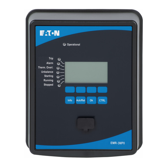
1 EMR‑3MP0 Motor Protection Relay 1.2 Information About the Device 1.2.2 Front Panel The following illustration applies to protective devices with “B1” housing, in particular the EMR-3MP0: Operational Info Ack/Rst CTRL 9 10 www.eaton.com EMR-3MP0... -
Page 25: Front Panel Parts
(2) LED »System OK« (“Operational”) The »Operational« (“System OK”) LED is constantly green when – after the boot phase, ╚═▷ “10 Boot Phase” – the protection functions of the EMR-3MP0 are working. In any other case consult the Troubleshooting Guide. (3) Display Via the display you can check operational data and edit parameters. - Page 26 (9) »OK« Key When using the »OK« key parameter changes are temporarily stored. If the »OK« key is pressed again, those changes are stored definitely. (10) »CTRL« Key Direct Access to a special page with a list of measurement values. www.eaton.com EMR-3MP0...
-
Page 27: Softkey Symbols
Via the »Key« symbol you are asked for password authorization, then you can change the selected parameter. Via Softkey »delete« the selected data is deleted. Fast forward scrolling is possible via Softkey »Fast forward«. Fast backward scrolling is possible via Softkey »Fast backward«. EMR-3MP0 www.eaton.com... -
Page 28: Modules, Settings, Signals And Values
1.3 Modules, Settings, Signals and Values Modules, Settings, Signals and Values The EMR-3MP0 is a digital protection device that holds various data in its internal memory. Some data is meant to be changed by the user to adapt the functionality to the respective application, other data types are set by the device during run-time and are therefore read-only from the user's perspective. - Page 29 For example, every protection function features several blocking parameters. (See also ╚═▷ “Blockings”.) If a signal has been assigned to a blocking parameter then the respective protection function gets blocked as soon as the run-time state of the assigned signal becomes “True”. EMR-3MP0 www.eaton.com...
- Page 30 1 EMR‑3MP0 Motor Protection Relay 1.3 Modules, Settings, Signals and Values • In the same way can signals also be assigned to the LEDs of the EMR-3MP0, so that an LED is lit as soon as the assigned signal becomes “True”. (See also ╚═▷...
-
Page 31: Parameter Settings
• press the »OK« key for saving changed parameters directly and to have them adopted by the device. Confirm the parameter changes by pressing the »Yes« Softkey or dismiss by pressing »No«. To change additional parameters and save afterwards, • move to other parameters and change them EMR-3MP0 www.eaton.com... - Page 32 A star/parameter change indication is always overwritten by the question mark/ implausibility symbol. If a device detects an implausibility, it rejects saving and adopting of the parameters. www.eaton.com EMR-3MP0...
- Page 33 Press the»OK« key to initiate the final storage of all parameter changes. Confirm the parameter changes by pressing the »Yes« Softkey or dismiss by pressing Softkey »No«. EMR-3MP0 www.eaton.com...
- Page 34 The program mode can be bypassed by means of the Direct Control Parameter [System Para / General Settings] »Program Mode Bypass«. The protective device will fall back into the Program Mode as follows: • Directly after a parameter change has been saved, or www.eaton.com EMR-3MP0...
- Page 35 1 EMR‑3MP0 Motor Protection Relay 1.3 Modules, Settings, Signals and Values • 10 minutes after the bypass has been activated. EMR-3MP0 www.eaton.com...
-
Page 36: Menu Structure
Select the protocol for (SCADA) communication with the substation. Device Parameters This menu branch features all settings that are directly related to the device, for example: Device Para • Settings for the Recorders • Communication settings www.eaton.com EMR-3MP0... - Page 37 • timer and memory functions Service This menu branch is primarily needed for testing purposes. For example: Service • Force / disarm outputs • Force / disarm analog input and outputs • Use the internal signal/fault generator • Reboot the protection device EMR-3MP0 www.eaton.com...
-
Page 38: Device Parameters
The user cannot set time and date manually (manual changes are ignored), if the clock of the protective device is synchronized automatically (e. g. via IRIG‑B or SNTP). Version Within the [Device Para / Version] menu, the user can obtain information on the software and hardware versions. www.eaton.com EMR-3MP0... -
Page 39: System Settings
The system settings define all parameters that are relevant for the primary side and the mains operational method like frequency, primary and secondary values. All system settings are accessible via the menu branch [System Para]. See the Reference Manual for detailed tables of all settings that are available for the EMR-3MP0. EMR-3MP0 www.eaton.com... -
Page 40: Device Planning
The manufacturer does not accept liability for any personal or material damage as a result of incorrect planning. Contact your Eaton Customer Service representative for more information. WARNING! Beware of the inadvertent deactivating of protective functions/modules, because all the settings of a deativated module get lost (i. e. -
Page 41: Security
1.4 Security Security CAUTION! All security settings have to be made by the user of the EMR-3MP0! It is strictly recommended that you adapt the security settings according to the local regulations and requirements at the end of the commissioning procedure. - Page 42 4 digits as minimum. The manufacturer will not take over any liability for any personal injuries or damages that are caused by deactivated password protection. www.eaton.com EMR-3MP0...
-
Page 43: Passwords - Areas
1.4.1.2 Passwords – Areas The access authorizations are designed in form of two hierarchic strands. The supervisor (administrator) password provides access to all parameters and settings. EMR-3MP0 www.eaton.com... - Page 44 The following table shows the access areas. Note that each access area requires its own authorization password in order to access it. (However, for a EMR-3MP0 that is reset to factory defaults all these passwords equal the same default password, see ╚═▷...
- Page 45 Reference Manual: “S.3” NOTICE! If the device was not active within the parameter setting mode for some time (can be set between 20 – 3600 seconds) it changes into »Read Only-Lv0« mode automatically. All unsaved parameter changes get canceled. EMR-3MP0 www.eaton.com...
- Page 46 Only-Lv0« and all unsaved parameter changes get canceled. CAUTION! Do not leave the EMR-3MP0 unsupervised as long as there are still access areas (levels) unlocked (unlocked lock symbol on the display). If the access is no longer needed it is advisable to reset the permissions back to »Read Only-Lv0«.
-
Page 47: Network Access
Detailed information can be found in the technical literature. Intranet Security If the Ethernet interface of the EMR-3MP0 is connected to a network it is the responsibility of the user to maintain all necessary means required for the security of the company network. -
Page 48: Reset To Factory Defaults, Reset All Passwords
1 EMR‑3MP0 Motor Protection Relay 1.4 Security internet) to the EMR-3MP0 has been made impossible. Please keep yourself informed about up-to-date technology (firewalls, VPN etc.)! 1.4.3 Reset to Factory Defaults, Reset All Passwords There is a dedicated Reset dialog that allows for selecting any of the following options: •... - Page 49 If the password should be lost and the »Reset all passwords« option has been made unavailable then the only chance to recover control is to reset the EMR-3MP0 to factory default. If this option has been deactivated, too, then the EMR-3MP0 has to be sent to the manufacturer as a service request.
-
Page 50: Resets
• Short keypress: With intermediate selection step: After the »Ack/Rst« key has been pressed (for a short time), you select the items to be reset (LEDs, SCADA, Relay Outputs, trips) via the Softkeys. After this, you press the Softkey with the »Wrench- Symbol«. www.eaton.com EMR-3MP0... - Page 51 [Device Para / Ex Acknowledge] »Ack LED« ✔ Assigned signal resets all LEDs. [Device Para / Ex Acknowledge] »Ack RO« ✔ Assigned signal resets all binary output relays. [Device Para / Ex Acknowledge] »Ack Comm« ✔ Assigned signal resets latched SCADA signals. EMR-3MP0 www.eaton.com...
- Page 52 In the [Operation / Reset] menu, the user can: • Reset counters; • Delete records (e. g. waveform records); and • Reset special things (like thermal replica, etc.). NOTICE! The description of the reset commands can be found within the corresponding modules of the Reference Manual. www.eaton.com EMR-3MP0...
-
Page 53: Measuring Values
If, however, it happens that the amplitude of the reference phasor becomes too small, the next possible measurement channel is used as the reference phasor, i. e. IB. If this, too, is not healthy the EMR-3MP0 proceeds with IC. By definition the reference phasor has a phase angle of 0°. -
Page 54: Measurement
Eaton offers a set of various ready-to-use Measurement Pages in *.ErPage format. Check your product CD that has been part of the delivery, or contact your Eaton representative. From the technical point of view, a Measurement Page is comparable to a Single-Line diagram or Control Page, but it can feature only measurement values. - Page 55 ╚═▷ “1.3 Types of Settings, Signals and Values”), the Measurement Page is also saved. Therefore you do not need the *.ErPage file again when you configure the next EMR-3MP0, it is sufficient to open the *.ErPara file in PowerPort-E and transfer it to the EMR-3MP0. EMR-3MP0...
-
Page 56: Powerport-E
For PowerPort-E, a PC with Windows (7, 8.x or 10) operating system is required. Moreover, a connecting cable is required for a direct connection of the EMR-3MP0 with the PC. This cable requires an USB connector of type “Mini B” on the EMR-3MP0 end (see also ╚═▷ “Slot X120 - PC Interface”). -
Page 57: Qualitymanager
• Save window setups (snapshots) and print for reporting • Open industry standard COMTRADE files from other intelligent electronic devices • Convert downloaded waveform files to COMTRADE file format using “Export” feature EMR-3MP0 www.eaton.com... -
Page 58: Hardware
Note about the parts marked by (*) in the following diagrams: There are two pieces of metal, the so-called “T-Connectors” that are necessary for fastening a special MP‑3000- compatibility adapter frame. If these are fixed to the EMR-3MP0 the width of the housing is increased by approx. 5.4 mm [~0.21 in.]. - Page 59 [4.92] 124.93 [2.45] [max. 5.88] 62.15 max. 149.43 Fig. 3: Outline Projection Panel Mount, door cutout. All dimensions in mm, except dimensions in brackets [inch]. For the “(*)” marking, see the Notice at the beginning of the chapter. EMR-3MP0 www.eaton.com...
- Page 60 [6.80] 172.65 [max. 7.76] [0.50] max. 197.15 12.75 Fig. 4: Outline Standard Panel Mount, door cutout. All dimensions in mm, except dimensions in brackets [inch]. For the “(*)” marking, see the Notice at the beginning of the chapter. www.eaton.com EMR-3MP0...
-
Page 61: Emr-3Mp0 - Installation And Wiring
2 Hardware 2.2 EMR-3MP0 – Installation and Wiring EMR-3MP0 – Installation and Wiring 2.2.1 Grounding WARNING! The housing must be carefully grounded. Connect a ground cable (protective earth, 4 to 6 mm2 [AWG 11‒9], tightening torque 1.7 Nm [15 lb⋅in]) to the housing, using the screw that is marked with the ground symbol (at the rear side of the device). -
Page 62: Control Wiring Diagram
Relay-1 This relay has to be a normally open X2-3 X2-4 to ensure that protection is enabled when motor is started. Auxiliary Trip Relay-2 X2-5 X2-6 Fig. 5: Typical CT Circuits and Motor Control Wiring for the EMR-3MP0. www.eaton.com EMR-3MP0... - Page 63 2 Hardware 2.2 EMR-3MP0 – Installation and Wiring Relay-3 X1-13 X2-5 Block X2-8 50/51/N X2-9 Start X1-9 X2-6 Typical Schematic for Feeder Breaker Fig. 6: Typical Schematic for Feeder Breaker for the EMR-3MP0. EMR-3MP0 www.eaton.com...
- Page 64 750 VA Fuse 1 PLUG 120V START Ground STOP 9 4 7 4160 Vac 60 Hz Fig. 7: Typical Wiring Diagram for Reduced Voltage for the EMR-3MP0. Please refer to the file “EMR-3MP0_wiring_diagrams.pdf” on your User Manual CD. www.eaton.com EMR-3MP0...
-
Page 65: Overview Of Slots - Assembly Groups
The exact installation place of the individual modules can be learned from the connection diagram fixed at the top of your device. Front Side The front side of the EMR-3MP0 equipped with a USB interface, that can be used to establish a connection with the setting software PowerPort-E. •... -
Page 66: Communication Protocol Codes
2 Hardware 2.2 EMR-3MP0 – Installation and Wiring 2.2.4 Communication Protocol Codes The following table lists the “Communication Options” letters from the Order Code (see ╚═▷ “Catalog Codes for the EMR-3MP0”), together with the respective communication interfaces and protocols that are available with this order option. - Page 67 2 Hardware 2.2 EMR-3MP0 – Installation and Wiring Interface Available Communication Protocols Ethernet 100MB / RJ45 IEC61850, Modbus TCP, DNP3.0 TCP/UDP ╚═▷ “Ethernet - RJ45” ╚═▷ “Modbus®” ╚═▷ “DNP3” RS485 / terminals Modbus RTU, DNP3.0 RTU ╚═▷ “RS485 - Modbus® RTU”...
- Page 68 2 Hardware 2.2 EMR-3MP0 – Installation and Wiring Interface Available Communication Protocols Ethernet 100 MB/RJ45 ╚═▷ “Ethernet - RJ45” www.eaton.com EMR-3MP0...
-
Page 69: Legend For Wiring Diagrams
2 Hardware 2.2 EMR-3MP0 – Installation and Wiring 2.2.5 Legend for Wiring Diagrams In this legend designations of various device types are listed, e. g. transformer protection, motor protection, generator protection, etc. Therefore it can occur that not every designation actually appears on the wiring diagram of your device. - Page 70 2 Hardware 2.2 EMR-3MP0 – Installation and Wiring • GND — Ground • HF Shield — Connection cable shield • Fiber Optics — Fiber optic connection Only for use with external galvanic decoupled CT’s. See chapter Current Transformers • of the manual! —...
-
Page 71: Slot X1
2 Hardware 2.2 EMR-3MP0 – Installation and Wiring 2.2.6 Slot X1 • Power Supply Card with Digital Inputs Slot1 Slot2 Slot3 X100 X103 Fig. 9: Rear side of the device (Slots). The type of power supply card and the number of digital inputs on it used in this slot is dependent on the ordered device type. -
Page 72: Di-4 X1 - Power Supply And Digital Inputs
2 Hardware 2.2 EMR-3MP0 – Installation and Wiring 2.2.6.1 DI-4 X1 - Power Supply and Digital Inputs WARNING! In addition to the grounding of the housing (protective earth, see ╚═▷ “Grounding”) there must be an additional ground cable connected to the power supply card (functional earth, min. - Page 73 2 Hardware 2.2 EMR-3MP0 – Installation and Wiring Functional Earth V+ Power Supply N.C. N.C. N.C. N.C. N.C. COM1 COM2 N.C. N.C. Fig. 10: DI-4 X1 - Terminal Marking DI-4P X Functional Earth Power Supply N.C. N.C. N.C. N.C. N.C.
- Page 74 The module is provided with 4 grouped digital inputs. The assignment of the digital inputs is descibed in ╚═▷ “Digital Input Configuration”. Check the “EMR-3MP0 Reference Manual” (separate document) for available signal assignments. CAUTION! When using DC supply, the negative potential has to be connected to the common terminal (COM1, COM2, COM3 - please see the terminal marking).
- Page 75 2 Hardware 2.2 EMR-3MP0 – Installation and Wiring • “60 Vdc” • “125 Vdc” • “250 Vdc” • “110/120 Vac” • “230/240 Vac” If a voltage >80% of the set switching threshold is applied at the digital input, the state change is recognized (physically “1”).
-
Page 76: Slot X2
2 Hardware 2.2 EMR-3MP0 – Installation and Wiring 2.2.7 Slot X2 • Relay Output Card • SC (Supervision Contact) Slot1 Slot2 Slot3 X100 X103 Fig. 12: Rear side of the device (Slots). The type of card in this slot is dependent on the ordered device type. -
Page 77: Or3-Ano-Ir - Assembly Group With 3 Relay Outputs, Supervision Contact
2 Hardware 2.2 EMR-3MP0 – Installation and Wiring 2.2.7.1 OR3-AnO-Ir – Assembly Group with 3 Relay Outputs, Supervision Contact, Analog Output, IRIG‑B WARNING! Ensure the correct tightening torques (see diagram). Connection cross section: min. 0.25 mm² (AWG 23) … max. 2.5 mm² (AWG 14) with or without wire end ferrule. - Page 78 The assignment of the Relay Outputs is described in ╚═▷ “Relay Output Configuration”. Check the “EMR-3MP0 Reference Manual” (separate document) for a list of signals that can be assigned. CAUTION! Please carefully consider the current carrying capacity of the Relay Outputs. Please refer to the Technical Data (╚═▷...
-
Page 79: Slot X3
2 Hardware 2.2 EMR-3MP0 – Installation and Wiring 2.2.8 Slot X3 • CTs (Current Measuring Inputs) Slot1 Slot2 Slot3 X100 X103 Fig. 15: Rear side of the device (Slots). Available assembly groups in this slot: • TI: Phase and Ground Current Measuring Input Card, standard sensitivity. -
Page 80: Phase And Ground Current Measuring Input Cards
2.2.8.1 Phase and Ground Current Measuring Input Cards For the EMR-3MP0, there are two measuring cards available, the standard phase and ground current card “TI”, and a special MP‑3000-compatible current input card “TI‑MP”. Both cards are different with respect to the mechanical layout, and there is one important difference with respect to the terminals: •... - Page 81 2 Hardware 2.2 EMR-3MP0 – Installation and Wiring WARNING! • Make sure the transformation ratios and the power of the CTs are correctly rated. If the rating of the CTs is not right (overrated), then the normal operational conditions may not be recognized. The pickup value of the measuring unit amounts approx. 3% of the rated current of the device.
- Page 82 2 Hardware 2.2 EMR-3MP0 – Installation and Wiring 2.2.8.1.1 “TI” – Standard Phase and Ground Current Measuring Input Card WARNING! Ensure the correct tightening torques (see diagram). Connection cross section: • 1 x or 2 x 2.5 mm² (2 x AWG 14) with wire end ferrule, or: •...
- Page 83 2 Hardware 2.2 EMR-3MP0 – Installation and Wiring .2.8.1.1.1 Connecting the Inputs The Phase and Ground Current Measuring Input Card supports both pin-terminal connections and ring-terminal connections. For either connection type, the first step is to remove the terminals from the device by opening the screws.
- Page 84 2 Hardware 2.2 EMR-3MP0 – Installation and Wiring Move the slider aside, so that the screws and metal plates become fully accessible. Every terminal consists of a screw with a non-losable metal contact. Screw (plus contact) can be unscrewed completely.
- Page 85 2 Hardware 2.2 EMR-3MP0 – Installation and Wiring 2.2.8.1.2 “TI‑MP” – MP‑3000-Compatible Current Input Card WARNING! Ensure the correct tightening torques for the current connection terminals: 9.0 lb⋅in (1.00 Nm). 1.00 Nm 9.0 lb⋅in EMR-3MP0 Fig. 17: TI‑MP – Terminal Marking EMR-3MP0 www.eaton.com...
-
Page 86: Common Ct Wiring Configurations
2 Hardware 2.2 EMR-3MP0 – Installation and Wiring 2.2.8.2 Common CT Wiring Configurations Check the installation direction. DANGER! It is imperative that the secondary sides of measuring transformers be grounded. DANGER! The current measuring inputs may exclusively be connected to current measuring transformers (with galvanic separation). - Page 87 2 Hardware 2.2 EMR-3MP0 – Installation and Wiring 2.2.8.2.1 Wiring Examples, CT Input Card “TI” 3-Phase, 3-Wire IG Measured EMR-3MP0 I̲ A ' I̲ A I̲ B ' I̲ B I̲ C ' I̲ C IX meas = IG Fig. 18: 3-phase, 3-wire IG measured; 5 A CT inputs.
- Page 88 2 Hardware 2.2 EMR-3MP0 – Installation and Wiring 2.2.8.2.2 Wiring Examples, CT Input Card “TI‑MP” 3-Phase, 3-Wire IG Measured EMR-3MP0 I̲ A ' I̲ A I̲ B ' I̲ B I̲ C ' I̲ C IX meas = IG Fig. 19: 3-phase, 3-wire IG measured; 5 A CT inputs.
-
Page 89: Slot X100: Ethernet Interface
2 Hardware 2.2 EMR-3MP0 – Installation and Wiring 2.2.9 Slot X100: Ethernet Interface Slot1 Slot2 Slot3 X100 X103 Fig. 20: Rear side of the device (Slots). An Ethernet interface may be available depending on the ordered device type. NOTICE! The available combinations can be gathered from the ordering code. -
Page 90: Ethernet - Rj45
2 Hardware 2.2 EMR-3MP0 – Installation and Wiring 2.2.9.1 Ethernet - RJ45 Fig. 21: RJ45 - Terminal Marking www.eaton.com EMR-3MP0... -
Page 91: Slot X101
2 Hardware 2.2 EMR-3MP0 – Installation and Wiring 2.2.10 Slot X101 • URTD Slot1 Slot2 Slot3 X100 X103 Fig. 22: Rear side of the device (Slots). Depending on the ordered device type, this slot can be equipped with an URTD interface. -
Page 92: 2.2.10.1 Interface For The Urtd Module
2 Hardware 2.2 EMR-3MP0 – Installation and Wiring 2.2.10.1 Interface for the URTD Module The Universal Resistance-Temperature Detector (URTD) module has to be connected to the protective device at the special fiber optic interface (1 optical slave). Fig. 23: Interface for the External URTD Module – Terminal Marking Fig. -
Page 93: Slot X103: Data Communication
2 Hardware 2.2 EMR-3MP0 – Installation and Wiring 2.2.11 Slot X103: Data Communication Slot1 Slot2 Slot3 X100 X103 Fig. 25: Rear side of the device (Slots). The data communication interface in the X103 slot is dependent on the ordered device type. -
Page 94: 2.2.11.1 Rs485 - Modbus® Rtu
2 Hardware 2.2 EMR-3MP0 – Installation and Wiring 2.2.11.1 RS485 - Modbus® RTU WARNING! Ensure the correct tightening torques. 0.3 Nm 2.65 lb⋅in 0.23 Nm 2.03 lb⋅in Protective Relay 120Ω Fig. 26: Modbus® RTU – Terminal Marking Protective Relay R1 = 560Ω... - Page 95 2 Hardware 2.2 EMR-3MP0 – Installation and Wiring Protective Relay R1 = 560Ω R2 = 120Ω B(+) B(+)* A(-)* A(-) Fig. 28: Modbus® RTU – Wiring Example: Device in the Middle of the Bus Protective Relay R1 = 560Ω R2 = 120Ω...
- Page 96 2 Hardware 2.2 EMR-3MP0 – Installation and Wiring 2.2nF 2.2nF 2.2nF 2.2nF (internal) (internal) (internal) (internal) Shield at bus master side Shield at bus device side Shield at bus master side Shield at bus device side connected to earth connected to earth...
- Page 97 2 Hardware 2.2 EMR-3MP0 – Installation and Wiring 2.2nF 2.2nF 2.2nF 2.2nF (internal) (internal) (internal) (internal) Shield at bus master side Shield at bus device side Shield at bus master side Shield at bus device side connected to earth connected to earth...
-
Page 98: 2.2.11.2 Profibus Dp/ Modbus® Rtu Via Fiber Optic
2 Hardware 2.2 EMR-3MP0 – Installation and Wiring 2.2.11.2 Profibus DP/ Modbus® RTU via Fiber Optic Fig. 32: Fiber Optic – FO, ST connector WARNING! Do not look directly into the light beam that is emitted from the fiber optics connector! Serious injury of the eyes can be consequence of ignoring this warning. -
Page 99: 2.2.11.3 Profibus Dp Via D-Sub
2 Hardware 2.2 EMR-3MP0 – Installation and Wiring 2.2.11.3 Profibus DP via D‑SUB D-SUB assignment - bushing • 1: Shield • 3: RxD TxD - P: High-Level • 4: RTS-signal • 5: DGND: Ground, neg. Potential of aux voltage supply •... -
Page 100: 2.2.11.4 Modbus® Rtu Via D-Sub
2 Hardware 2.2 EMR-3MP0 – Installation and Wiring 2.2.11.4 Modbus® RTU via D‑SUB D-SUB assignment - bushing • 1: Shield • 3: RxD TxD - P: High-Level • 4: RTS-signal • 5: DGND: Ground, neg. Potential of aux voltage supply •... -
Page 101: 2.2.11.5 Ethernet / Tcp/Ip Via Fiber Optics
2 Hardware 2.2 EMR-3MP0 – Installation and Wiring 2.2.11.5 Ethernet / TCP/IP via Fiber Optics RxD TxD Fig. 33: Fiber Optics – FO, LC duplex connector. CAUTION! After plugging in the LC connector, fasten the metal protecting cap. The tightening torque for the screw is 0.3 Nm [2.65 lb⋅in]. -
Page 102: Slot X120 - Pc Interface
2.2.12 Slot X120 - PC Interface There is an USB interface of type “Mini-B” located at the front panel of the EMR-3MP0. This interface can be used to connect the EMR-3MP0 to a PC, so that the operating software PowerPort-E can be used for configuration and data analysis. -
Page 103: Input, Output And Led Settings
Via the »INFO« button it is always possible to display the signals that are currently assigned to an LED. Main LED overview: If the »INFO« key is pressed once, the »main overview of the left LEDs« are displayed. EMR-3MP0 www.eaton.com... - Page 104 This also applies if it is re-configured to »Latched« = “Inactive”. • Switching off the EMR-3MP0 does not reset latched LEDs, because after a (warm or cold) restart, every latched LED will return to its individual (previously assumed) state.
- Page 105 System OK (Operational) lights up in green, signaling that the protection (function) is »activated«. Please refer to ╚═▷ “Self-Supervision” and to the external document Troubleshooting Guide to find out further information on blink codes of the System OK LED. EMR-3MP0 www.eaton.com...
-
Page 106: Digital Input Configuration
(Please note, this has to marked with the cursor). The assignment can now be deleted at the HMI by means of the Softkey »Parameter setting« and selection of »remove«. Confirm the parameter setting update. www.eaton.com EMR-3MP0... - Page 107 ”...” next to a Digital Input. Call up this Digital Input by Softkey »Arrow right« in order to see the list of targets of this Digital Input. EMR-3MP0 www.eaton.com...
-
Page 108: Relay Output Configuration
The relay output contacts are “dry- type“ contacts. • By the »Operating Mode« it can be determined whether the relay output works in Normally »De-Energized« or »Normally Energized« principle. NOTICE! The »System OK Relay« (watchdog) cannot be configured. www.eaton.com EMR-3MP0... -
Page 109: Configuration Of The Analog Outputs
The user defines a »Range min« and a »Range max«. The »Range min« determines the value at which value the transmission starts. Likewise, the »Range max« value determines the value that results in the end value of the transmission. 100% Range min Range max Range of assigned value EMR-3MP0 www.eaton.com... -
Page 110: Communication Protocols
EMR-3MP0”, ╚═▷ “Communication Protocol Codes”). You have to define which one of the available SCADA protocols the EMR-3MP0 shall use. This is done by setting [Device Planning] »Protocol« to the required communication protocol. After this, you have to make some more settings related to the selected protocol. -
Page 111: Tcp/Ip Settings
The other TCP/IP settings – see below – can only be set after »TCP/IP« has been set to “Active”. • »IP address« – the IPv4 address of the EMR-3MP0. • »Subnet mask« – the subnet mask that defines the IP address range of your local network. - Page 112 3.2 TCP/IP Settings Moreover, there are some special settings in the menu branch [Device Para / TCP/IP / Advanced Settings], see the Reference Manual. Only in very rare situations will it be necessary to modify their default values. www.eaton.com EMR-3MP0...
-
Page 113: Modbus
For detailed information on data point lists and error handling, please refer to the Modbus® documentation. To allow configuration of the devices for Modbus® connection, some default values of the control system must be available. Modbus RTU Part 1: Configuration of the Devices EMR-3MP0 www.eaton.com... - Page 114 • Parity error; can be obtained from the event recorder. Error Handling – Errors on Protocol Level If, for example, an invalid memory address is inquired, error codes will be returned by the device that need to be interpreted. www.eaton.com EMR-3MP0...
- Page 115 Part 3: Hardware Connection • There is a RJ45 interface at the rear side of the device for the hardware connection to the control system. • Establish the connection to the device by means of a proper Ethernet cable. EMR-3MP0 www.eaton.com...
-
Page 116: Profibus
╚═▷ “Catalog Codes for the EMR-3MP0”, ╚═▷ “Communication Protocol Codes”): At the rear side of the EMR-3MP0, there is either an RS485 (D-SUB) interface or an optic fiber (ST connector) interface available for the Profibus connection. • Connect bus and EMR-3MP0. - Page 117 3 Communication Protocols 3.4 Profibus • Baud Found — green flashing • Data Exchange — green • Profibus protocol not selected at [Device Planning] »SCADA . Protocol« — red EMR-3MP0 www.eaton.com...
- Page 118 • Parameter setting of the IEDs • Ethernet installation • TCP/IP settings for the IEDs • Wiring according to wiring scheme Commissioning steps for a substation with IEC 61850 environment: • Parameter setting of the IEDs • Ethernet installation www.eaton.com EMR-3MP0...
- Page 119 • Click on the SCD icon in the IEC 61850 window. • Select a drive and file name for the SCD file and click “save”. • Repeat the steps 1 to 6 for all connected devices in this IEC 61850 environment. EMR-3MP0 www.eaton.com...
- Page 120 • (9.) Following Step 5, again switch on the IEC Communication and submit the changed parameter set into the device. • (10.) Repeat Steps 1 through 9 for all devices connected to this IEC 61850 environment. • If no error message occurs, the configuration has been completed successfully. www.eaton.com EMR-3MP0...
- Page 121 VirtualInput] »Quality of GGIO Inx«. GOOSE Status The status of the GOOSE connection can be checked at [Operation / Status Display / IEC 61850 / State] »All Goose Subscriber active«. This signal summarizes the Quality of all Virtual Inputs (see above). EMR-3MP0 www.eaton.com...
-
Page 122: Dnp3
Self Addressing is available for DNP-TCP. That means that the Master and Slave id are auto-detected. NOTICE! Some Output signals (that are for a short time active only) have to be acknowledged separately (e. g. Trip signals) by the Communication System. www.eaton.com EMR-3MP0... - Page 123 • Analog Inputs (e. g. measured values to be send to the master). Please take into account that floating values have to be transmitted as integers. That means they have to be scaled (multiplied) with a scaling factor in order to bring them into the integer format. EMR-3MP0 www.eaton.com...
- Page 124 Please try to avoid gaps that will slow down the performance of the DNP communication. That means do not leave unused inputs / outputs in between used inputs / outputs (e. g. do not use Binary Output 1 and 3 when 2 is unused). www.eaton.com EMR-3MP0...
-
Page 125: Application Example: Setting A Relay
DNP Binary Outputs are pulse signals (by DNP definition, not steady state). Steady states can be created by means of Logic functions. The Logic Functions can be assigned onto the Relay Inputs. Please note: You can use a Set/Reset element (Flip Flop) from Logics. EMR-3MP0 www.eaton.com... -
Page 126: Time Synchronization
Recommended alternative to IRIG-B, especially when using IEC 61850 or Modbus TCP. Modbus RTU Hardware Interface Recommended Application RS485, D-SUB or Fiber Optic Recommended when using Modbus RTU communication protocol and when no IRIG-B real time clock is available. www.eaton.com EMR-3MP0... - Page 127 Daylight Saving Time (i. e. the change between summer- and wintertime) can be configured. Please carry out the following setting steps in the menu branch [Device Para / Time / Timezone]: • Set the parameter »Time Zones« to your local timezone. EMR-3MP0 www.eaton.com...
- Page 128 • Then, in the menu branch [Device Para / Time / Timezone], set the parameter »Time Zones« to your local timezone. • Then configure the switching of daylight saving time. • Set date and time at [Device Para / Time] »Date and Time«. www.eaton.com EMR-3MP0...
-
Page 129: Sntp
• Precision: This is the accuracy, the SNTP server provides the system time. Also the performance (traffic and data package transmission time) of the connected network has an influence on the accuracy of the time synchronization. A locally installed EMR-3MP0 www.eaton.com... - Page 130 • Check if the IP address of the SNTP server is set in the device at [Device Para / Time / TimeSync / SNTP]. • Check if SNTP is used for time synchronization at [Device Para / Time / TimeSync / TimeSync]. www.eaton.com EMR-3MP0...
- Page 131 • Check if the Ethernet connection is active: [Device Para / TCP/IP / TCP/IP config] »Link« = “Up”?. • Check if the SNTP server as well as the protection device answers to a Ping. • Check if the SNTP server is up and working. EMR-3MP0 www.eaton.com...
-
Page 132: Irig-B00X
Gnd Inst Trip Pickup Bkr Failure Maint. Mode Info Ack/Rst CTRL Twisted Pair Cable To Other Devices The location of the IRIG‑B interface depends to the device type. Please refer to the wiring diagram supplied with the protective device. www.eaton.com EMR-3MP0... - Page 133 18 control commands that can be processed by the protective device. They have to be set and issued by the IRIG‑B code generator. The EMR-3MP0 offers up to 18 IRIG-B assignment options for those control commands in order to carry out the assigned action. As soon as a control command is transmitted the state of the corresponding signal »IRIG-B .
-
Page 134: Protective Elements
These are always issued, independently of the setting »Alarm only«. • If »Alarm only« has been set to “No” then the master module »Prot« collects/ summarizes these signals and issues its own collective signals: »Prot . Pickup« / »Prot . Trip«. www.eaton.com EMR-3MP0... - Page 135 50P . Trip Phase A Prot . Pickup Phase A 50P . Trip Phase B Prot . Pickup Phase B 50P . Trip Phase C Prot . Pickup Phase C 50X . Trip Prot . Pickup IX or IR EMR-3MP0 www.eaton.com...
-
Page 136: Blockings
(***) Module input state: External blocking (during the motor start phase) Name . Function Inactive Active (***) There ia a built-in activation delay for some protective elements during motor start. See ╚═▷ “Delayed Protection Enabling During Motor Starts” for details. www.eaton.com EMR-3MP0... -
Page 137: Motor Starting And Control Module
Motor Operation States START From Other Trip Modules BLOCK STOP TRIP The basic motor operation states can be classified as four states that include: • Start cycle; • Run cycle; • Stop cycle; EMR-3MP0 www.eaton.com... - Page 138 After motor currents are terminated, the motor will go into the stop cycle. A motor start is blocked by the hidden state “Block” as shown in the motor start diagram, if any of the following conditions are noted – motor starts limit, starting frequency, thermal and mechanical constraints. www.eaton.com EMR-3MP0...
-
Page 139: Motor Start Blocked
Reason for Start Blocking: Too many starts per hour. [2.] Reason for Start Blocking: Waiting time between starts is not elapsed. [3.] Reason for Start Blocking: Reversing not allowed. [4.] Reason for Start Blocking: Thermal Blocking. [5.] Reason for Start Blocking: External Start Blocking. EMR-3MP0 www.eaton.com... -
Page 140: Reversing Or Non-Reversing Starter
The setting value »Reversing« = “Active” specifies that a motor start with reversed phase sequence is an acceptable operating condition. In this case the EMR-3MP0 accepts either sequence at the time of a start. The calculated symmetrical components (positive and... -
Page 141: Motor Start / Transition Trips
• There is an Incomplete Start Sequence. The device detects via an digital input that the external process is not properly started. • If a reverse direction is detected but reversing is not allowed. (See ╚═▷ “Reversing or Non-Reversing Starter”.) • If case of a Zero Speed Switch trip. EMR-3MP0 www.eaton.com... - Page 142 [1.] Trip during Motor Start. Reason: Motor Start Phase Supervision. [2.] Trip during Motor Start. Reason: External Process Failure. [3.] Trip during Motor Start. Reason: Zero Speed Switch Trip [4.] Trip during Motor Start. Reason: Reversing not allowed. www.eaton.com EMR-3MP0...
-
Page 143: Start Control
Initially, the motor is stopped and the current is zero. As long as the EMR-3MP0 is not in a trip state, it permits contactor energization by closing its trip contact in series with the contactor. The contactor is energized by the operator or process control system through a normal two-wire or three-wire motor control scheme, external to the protective device. - Page 144 »TRN Criteria« = “TRN T or I”, and »TRNC« = 130% ⋅ FLA. Modify the latter, if needed, to set it to a transition value between the starting current and the post-start maximum load current. Set the transition timer well beyond the normal start time to avoid a transition trip. www.eaton.com EMR-3MP0...
-
Page 145: Delayed Protection Enabling During Motor Starts
4.2 Motor Starting and Control Module 4.2.5 Delayed Protection Enabling During Motor Starts When the EMR-3MP0 detects a motor start, various timers are started. Each of these timers blocks a protective function until the set delay expires. (See ╚═▷ “Blockings”.) This way false trip decisions by these protection functions during the motor start are prevented. - Page 146 4 Protective Elements 4.2 Motor Starting and Control Module • JAM: The setting »t-Blo-JAM« defines the time (in seconds) after a start is recognized until the »50J[x]« protection modules (ANSI 50J functions) are enabled. www.eaton.com EMR-3MP0...
-
Page 147: Start Limits
Most motors can tolerate some number of consecutive cold starts before the time between starts is enforced. The EMR-3MP0 treats a start as the first in a sequence of cold starts if the motor had been stopped for at least one hour, or for the time period »TBS Timer«... -
Page 148: Stop Cycle
4.2.11 Blocked Condition Note that the protective device has two types of blocking outputs: individual block and a general block. The individual blocking functions are as follows: • Number of cold starts block; • Time between starts block; www.eaton.com EMR-3MP0... -
Page 149: Forced Starting
Digital Inputs. If the contact fails to open within »LRT/2« (one-half of locked-rotor time) after a start, the relay trips with a zero- speed switch trip message. This protection is always useful, but is essential if the Long Acceleration Time (LAT) function setting is used. EMR-3MP0 www.eaton.com... - Page 150 ZSS input status at the very moment it sees a start – it wants to sense the initially closed zero-speed switch, which opens shortly thereafter as the motor spins. If it fails to find the closed contact, it trips immediately. Check the wiring and contact for problems. www.eaton.com EMR-3MP0...
-
Page 151: Long Acceleration Time (Lat)
If »LAT« is used, check the settings of transition time »TRNT« and jam start delay to be sure they are coordinated with the prolonged starting cycle. EMR-3MP0 www.eaton.com... -
Page 152: Incomplete Sequence Report Back Time (Insq)
MStart . Run MStart . Start InSq Start2Run MStart . Stop InSq Stop2Start MStart . INSQ-I 50 ms >500 ms No Trip (<500 ms) No Trip Trip Trip (>500 ms) www.eaton.com EMR-3MP0... -
Page 153: Emergency Override
Using this function can damage the motor. Use it only for true emergencies, when it is known what caused the trip. Override permits the risk of motor damage to avoid an even more dangerous process situation caused by the tripping of the motor. EMR-3MP0 www.eaton.com... -
Page 154: Thermal Model
The value of K₂ = 6.01 is internally fixed, so that the EMR-3MP0 mimics the thermal model of Eaton's MP‑3000 and MP‑4000 motor relays. - Page 155 Take, for example, I = 6 FLA, T = 15 s, and thermal trip level of 100%. The relationship between the effective current threshold and the stator temperature can be seen in the Stator Temperature Effect on Current Threshold Curve. EMR-3MP0 www.eaton.com...
- Page 156 Thermal Replica Model Trip Curves 1000 Multiple of Full Load Ampere SF = 1, TC = 100% Ith = 120%, Tth = 80%⋅TC Fig. 37: Thermal Replica Model Limit and Trip Curves without RTD. www.eaton.com EMR-3MP0...
- Page 157 They will vary with other sets of the settings. NOTICE! When »WD Trip Function« = “Active”, the thermal model of the motor protection devices uses the hottest winding “WD” RTD value. EMR-3MP0 www.eaton.com...
-
Page 158: Locked Rotor Protection
The value of K₂ = 6.01 is internally fixed, so that the EMR-3MP0 mimics the thermal model of Eaton's MP‑3000 and MP‑4000 motor relays. -
Page 159: Ultimate Trip Current
If the RTDs, the module, or its communications to the relay fail, the algorithm falls back to use of UTC. Also, note that if all RTD channels are set to OFF, the algorithm reverts to the non- RTD calculation, which is based strictly on UTC. EMR-3MP0 www.eaton.com... -
Page 160: Motor Protection Curves
I1 and kI2.) Based upon locked rotor current of 6.1 times full-load amps Instantaneous overcurrent set at 12 times full-load amperes Instantaneous overcurrent start delay set for 2 cycles multiples of FLA Fig. 39: Motor Protection Curve (Example 1). www.eaton.com EMR-3MP0... - Page 161 Motor starting current for 2 cycle (locked rotor condition) 6.1 times full-load amperes multiples of FLA Fig. 40: Motor Protection Curve (Example 2 – without RTDs). Motor Protection Curve (Example 3 - with RTDs) EMR-3MP0 www.eaton.com...
- Page 162 12 times full - load amperes Instantaneous overcurrent: start delay set Motor starting current for 2 cycle (locked rotor condition) 6.1 times full-load amperes multiples of FLA Fig. 41: Motor Protection Curve (Example 2 – with RTDs). www.eaton.com EMR-3MP0...
-
Page 163: Mls - Load Shedding
The load shed function, which is active only during the RUN state of the motor, is configured with settings within the menu branch [Protection Para / MLS]. EMR-3MP0 www.eaton.com... -
Page 164: 50J - Jam And Stall Protection
JAM protection recognizes mechanical problems, such as broken drive gears. The EMR-3MP0 can be configured for a JAM alarm and/or a JAM trip. There are two JAM elements, »50J[1]«, »50J[2]«. Refer to the JAM protection limit (the right vertical line in the “Underload and JAM Trip Function”... - Page 165 • [Protection Para / 50J[x]] »Pickup« = 2.00 FLA Apply current of magnitude “2 FLA” for less than one second. The EMR-3MP0 should not trip. Apply the same current for 3 seconds. The EMR-3MP0 should trip in 2 to 3 seconds. EMR-3MP0...
-
Page 166: Underload Module
Refer to the underload protection limit – the left vertical line in the Underload and Jam Trip Function example. In the example, the underload trip is set at 60% of FLA. The protective device can be configured for underload alarm and underload trip. www.eaton.com EMR-3MP0... - Page 167 Each has its own run or pickup delay. Use the start delay to block tripping until the load stabilizes after a start. Use run delays to avoid nuisance alarms or trips for load transients. EMR-3MP0 www.eaton.com...
-
Page 168: Deft Overcurrent Protection
Instantaneous Current Curves (Characteristic) The following characteristic is available: • DEFT (definite time). Explanation • t = Tripping delay • I = Fault current • Pickup = If the pickup value is exceeded, the module/element starts to time out to trip. www.eaton.com EMR-3MP0... - Page 169 4 Protective Elements 4.8 50P – DEFT Overcurrent Protection DEFT I / Pickup 0.01 0.01 t [s] 300s 300s 0.0s 0.0s 0.01 0.01 I / Pickup Fig. 44: DEFT – Definite Time-Overcurrent EMR-3MP0 www.eaton.com...
- Page 170 This trip type can be set to Inactive to deactivate this protective device element. For currents clearly above the setting, the IOC function picks up in two power cycles or less. The IOC setting must be below (1.130 ⋅ PCT/ FLA) or 1.600%, whichever is less. www.eaton.com EMR-3MP0...
-
Page 171: Commissioning: Overcurrent Protection, Non-Directional [Ansi 50P]
3 x single-phase and 1 x three-phase. NOTICE! Eaton recommends measuring the total tripping time instead of the tripping delay. The tripping delay should be specified by the User. The total tripping time is measured at the position signaling contact of the breaker (not at the relay output contacts!). - Page 172 4 Protective Elements 4.8 50P – DEFT Overcurrent Protection deviations/tolerances can be found in the Technical Data section (╚═▷ “Tolerances / Specifications”). www.eaton.com EMR-3MP0...
-
Page 173: Deft Measured Ground Fault Protection
The DEFT Ground Overcurrent module »50X« covers the ANSI 50X protection function. It is non-directional, i. e. no directional information is taken into account. The following characteristic is available: • DEFT (definite time). For the tripping curves, please refer to ╚═▷ “Instantaneous Current Curves (Ground Current Measured)”, located in the Appendix. EMR-3MP0 www.eaton.com... -
Page 174: Functionality
(Element is not deactivated and no active blocking signals.) 50X . Pickup True RMS 50X . Pickup Φ IX meas ◄ 50X . 50X . Trip Pickup 50X . ↪ »Prot« Alarm only Trip ↪ »Prot« Fig. 45: Functionality of the ANSI 50X module. www.eaton.com EMR-3MP0... -
Page 175: Special Notes On Ground (Earth) Fault Current Transformers
C10), have long wiring runs, or are otherwise heavily burdened. 4.9.3 Commissioning: Ground Fault Protection – Non-Directional [ANSI 50X] Please test the non-directional ground overcurrent using the procedure for non-directional phase overcurrent protection, ╚═▷ “Commissioning: Overcurrent Protection, Non- directional [ANSI 50P]”. EMR-3MP0 www.eaton.com... -
Page 176: Current Unbalance Protection
• Three-phase current source with adjustable current unbalance; and • Timer. Procedure: Check the phase sequence: • Ensure that the phase sequence is the same as that set in the field parameters. • Feed-in a three-phase nominal current. www.eaton.com EMR-3MP0... - Page 177 • Feeding only phase A results in »%(I2/I1) = 100%«, so the first condition »%(I2/I1) >= 2%« is always fulfilled. • Now increase the phase A current until the relay is activated. Testing the dropout ratio of the threshold values EMR-3MP0 www.eaton.com...
- Page 178 Having tripped the relay in the previous test, now decrease the phase A current. The dropout of »%(I2/I1)« has to be 1% below the »%(I2/I1)«setting. Successful test result: The measured trip delays, threshold values, and dropout ratios are within the permitted deviations/tolerances, specified under Technical Data. www.eaton.com EMR-3MP0...
-
Page 179: Ex87 - External Differential Protection
Dependent on the application. Procedure: Simulate the functionality of the External Differential Protection (pickup, trip, and blockings) by (de-)energizing the digital inputs. Successful test result: All external pickups, external trips, and external blockings are correctly recognized and processed by the device. EMR-3MP0 www.eaton.com... -
Page 180: Remote Trip
Dependent on the application. Procedure: Simulate the functionality of the External Protection (pickup, trip, and blockings) by (de-)energizing the digital inputs. Successful test result: All external pickups, external trips, and external blockings are correctly recognized and processed by the device. www.eaton.com EMR-3MP0... -
Page 181: 26/38/49 - Rtd Protection Module
The Resistance-based Temperature Detector (RTD) Protection Module uses temperature data that are provided by Eaton's Universal Resistance-based Temperature Detector (URTD) module (please refer to the URTD Module section) or Eaton's Universal Resistance- based Temperature Detector II (URTDII) module (please refer to ╚═▷... - Page 182 Prot / RTD / Aux Group] ◦ Measured temperature values can be found in menu branch [Operation / Measured Values / URTD] Within each group, always the hottest RTD is used. Only these groups are used, the selective channels are not used. www.eaton.com EMR-3MP0...
- Page 183 The RTD sensors are assigned to four groups (depending on the ordered device). These four groups are OR-connected to the ”AnyGroup“. The AnyGroup generates an alarm, an timeout alarm and a trip signal if any of the sensors mounted into this issues the corresponding signal. EMR-3MP0 www.eaton.com...
- Page 184 Trip«. RTD . Trip RTD_E95 All trips are OR connected to a collective trip signal. RTD . Trip WD Group RTD . Trip MB Group RTD . Trip RTD . Trip LB Group RTD . Trip Aux Group www.eaton.com EMR-3MP0...
-
Page 185: Urtdii Module Interface
The optional Universal Resistance-based Temperature Detector II (URTDII) Module provides temperature data to the protective device up to 12 RTDs embedded in the motor, generator, transformer, or cable connector and driven equipment (see Eaton I.L. IL02602013E). The temperature data will be shown as measured values and statistics in the Operating Data menu. - Page 186 82.0 ft (25 m) MPFO-25 HBFR-ELS025 164.0 ft (50 m) MPFO-50 HBFR-ELS050 246.1 ft (75 m) MPFO-75 HBFR-ELS075 249.3 ft (76 m) MPFO-76 HBFR-ELS076 328.1 ft (100 m) MPFO-100 HBFR-ELS100 393.7 ft (120 m) MPFO-120 HBFR-ELS120 Uncut Fiber HBFR-EUS (Length) www.eaton.com EMR-3MP0...
- Page 187 The optical fiber is the only method of transmitting temperature data from the URTDII Module to the protective device. Preassembled plastic optical fibers with connectors can be ordered from Eaton, or from any distributor of Agilent Technologies® optical fiber products. In addition, these same distributors offer long rolls of cable with connectors that can be installed in the field.
- Page 188 The three terminals for any unused RTD input channel should be wired together. For example, if MW5 and MW6 are unused, MW5 terminals J2-15, J2-16, and J2-17 should be wired together and MW6 terminals J2-19, J2-20, J2- 21 should be separately wired together. www.eaton.com EMR-3MP0...
- Page 189 URTD end, and insulated at the RTD end. The RTDs themselves must not be grounded at the object to be protected. Remember to set the URTDII module DIP switches according to the types of RTDs in each of the channels (see I.L. IL02602013E). EMR-3MP0 www.eaton.com...
-
Page 190: Trip Bypass [50Bf/62Bf]
General Trip trigger signal drops off. This is reported by the status signal »Trip Bypass . Waiting for Trigger«. Breaker Failure Lockout The signal of the Breaker Failure is latched. This signal can be used to block the breaker against a switching on attempt. www.eaton.com EMR-3MP0... -
Page 191: Trip Bypass Functionality
»Trip Bypass . Trip« signal becomes active. To avoid wiring errors, make sure the breaker in the upstream system switches off. The time, measured by the timer, should be in line with the specified tolerances. Successful Test Result: EMR-3MP0 www.eaton.com... - Page 192 4 Protective Elements 4.15 Trip Bypass [50BF/62BF] The actual times measured comply with the setpoint times. The breaker in the higher- level section switches off. WARNING! Re-connect the control cable to the breaker! www.eaton.com EMR-3MP0...
-
Page 193: Recorders
Event Recorder collects status changes of binary states and counters of the various EMR-3MP0 modules, so that the user can get an overview of what has happened recently. The entries can be accessed on the HMI and via PowerPort-E at the menu branch [Operation / Recorders / Event rec]. - Page 194 [Operation / Recorders / Trend rec]. Moreover, a double-click on this summary within the Trend Recorder window in PowerPort-E enables the user to save all data in an *.ErTr file that can be opened in the QualityManager PC software for graphical analysis. www.eaton.com EMR-3MP0...
-
Page 195: Waveform Recorder
• Choose whether only the current or all waveform records should be deleted; and • Confirm by pressing »SOFTKEY« »OK«. Configuring the Waveform Recorder The waveform recorder can be configured in the [Device Para / Recorders / Waveform rec] menu. EMR-3MP0 www.eaton.com... - Page 196 In case »Auto overwriting« is »Active«, the oldest recorded waveform will be overwritten. If the parameter is set to »Inactive«, recording of the waveform events will be stopped until the storage location is manually released. www.eaton.com EMR-3MP0...
- Page 197 5 Recorders 5.1 Waveform Recorder Start: 1Trigger Start: 2Trigger Start: 3Trigger Start: 4Trigger Recording Start: 5Trigger Start: 6Trigger Start: 7Trigger Start: 8Trigger Man. Trigger EMR-3MP0 www.eaton.com...
- Page 198 = Max file size Pre-trigger time = 15% Max file size = 2s Start 1 1200 ms Pre-trigger time 300 ms Post-trigger time 500 ms t-rec 2000 ms Max file size 2000 ms Fig. 47: Example Waveform Recorder Timing Chart I www.eaton.com EMR-3MP0...
- Page 199 Post-trigger time = 25% Start 1 Pre-trigger time = 15% 200 ms Max file size = 2s Pre-trigger time 300 ms Post-trigger time 500 ms t-rec 1000 ms Max file size 2000 ms Fig. 48: Example Waveform Recorder Timing Chart II EMR-3MP0 www.eaton.com...
-
Page 200: Fault Recorder
Maint. Mode Info Ack/Rst CTRL Prot . Pickup Signal: General Pickup Fault duration Prot . Trip Signal: General Trip Time to trip Analog values (recording) t-meas-delay=0 t-meas-delay>0 Capture Data Capture Data Fig. 49: Fault Recorder: times and durations. www.eaton.com EMR-3MP0... - Page 201 Delete all the fault records in your fault recorder afterwards. Memory The last stored fault record is saved (fail-safe) within the Fault Recorder. (The others are saved within a volatile memory, that depends on the auxiliary power of the protective EMR-3MP0 www.eaton.com...
- Page 202 Part 2: Information specific to the protection function that detected the fault e. g. Fault type The bits of information given in this part depend on the protection module. For example, in case of phase-selective protection functions, there is also data about the single phases. www.eaton.com EMR-3MP0...
- Page 203 • Or close the Pop-up by using the Softkey OK. Option 2: • Enter the menu branch [Operation / Recorders / Fault rec]. • Select a fault record. • Analyze the fault record by using Softkeys “▲” and “▼”. EMR-3MP0 www.eaton.com...
-
Page 204: Event Recorder
• Old Counter state -> New Counter state (e. g.: 3->4) Alternation of multiple states are shown as: • Old state -> New state (e. g.: 0->2) Read the Event Recorder • Enter the menu branch [Operation / Recorders / Event rec]. • Select an event. www.eaton.com EMR-3MP0... -
Page 205: Trend Recorder
• Via PowerPort-E, however, you can make a double-click on the entry with the summary. This allows you to download the analog data from the EMR-3MP0 and save it to a file (with the filename extension *.ErTr). -
Page 206: Motor Start Recorder
However, the exact set of data is dependent on the ordered device variant. The summary data can be accessed using PowerPort-E or via the front panel interface of the EMR-3MP0. This feature provides information recorded at the time of each start of the motor such as: •... - Page 207 • Click on the button “Receive Summary Data”. • Click on the “Print” button. • Click on the button “Export to file”. • Enter a valid file name. • Select the file path. • Click on the “Save” button. EMR-3MP0 www.eaton.com...
- Page 208 • Analyze a Start Record: Since a Start Record does not include the relay settings, the user has to ensure that backups of the relay settings are available that were valid at the time of recording. www.eaton.com EMR-3MP0...
-
Page 209: Statistic Recorder
When using PowerPort-E, a double-click on the »Date of Record« shows detailed statistical information such as the number of starts, the number of successful starts, the average start time, the »average I2T« value during any start, and the average of all maximum currents value seen during each start. EMR-3MP0 www.eaton.com... -
Page 210: History Function
• A window opens with all counter details (for the selected group) in tabular form. To Reset the History Records at the HMI or with PowerPort-E • Enter the EMR-3MP0 menu [Operation / Reset / History]. • There are the following Direct Commands available in this menu branch: ◦... - Page 211 5 Recorders 5.7 History Function • Confirm the »Execute?« dialog. EMR-3MP0 www.eaton.com...
-
Page 212: Programmable Logic
• “1” for a NOR gate If at least one input signal is assigned to a gate all not assigned inputs are set to: • “1” for AND / NAND gates • “0” for an OR / NOR gates www.eaton.com EMR-3MP0... - Page 213 Active Inactive LE . Reset Latched No assignment 1..n, Assignment List LE . Inverting Reset Active Inactive Fig. 51: Detailed Overview – Overall Logic Diagram. Available Gates (Operators) Within the Logic Equation, the following Gates can be used. EMR-3MP0 www.eaton.com...
- Page 214 Cascading in an ascending sequence means that the user utilizes the output signal of “Logic Equation n” as input of “Logic Equation n+1”. If the state of “Logic Equation n” changes, the state of the output of “Logic Equation n+1” will be updated within the same cycle. www.eaton.com EMR-3MP0...
- Page 215 “Logic Equation n+1” as input of “Logic Equation n”. If the output of “Logic Equation n +1” changes, this change of the feed back signal at the input of “Logic Equation n” will be delayed for one cycle. EMR-3MP0 www.eaton.com...
- Page 216 Improper use of logic equations might result in personal injury or damage the electrical equipment. Do not use logic equations unless the user can ensure the safe functionality. How to configure a logic equation? • Within the Device Planning, set the number of required Logic Equations. • Enter the [Logic] menu. www.eaton.com EMR-3MP0...
- Page 217 In case the logic equations should be cascaded, the User has to be aware of timing delays (cycles) in case of descending sequences (Please refer to the Cascading Logical Outputs section). By means of the Status Display [Operation / Status Display], the logical states can be verified. EMR-3MP0 www.eaton.com...
-
Page 218: Self-Supervision
(fatal internal error). Parameter Setting (Device) Protecting the parameter Implausibilities within the setting by plausibility checks. parameter configuration can be www.eaton.com EMR-3MP0... - Page 219 Status of the device The projected and activated You can check if there is active communication (SCADA) SCADA module supervises its communication with the master connection to the master system within menu communication system. EMR-3MP0 www.eaton.com...
- Page 220 Device reboot triggered by the operator via HMI or PowerPort-E. Reboot by means of Super Reset Automatic reboot when setting the device back to factory defaults. -- (outdated) -- (outdated) Unknown Error Source Reboot due to unknown error source. www.eaton.com EMR-3MP0...
- Page 221 The menu [Operation / Self-Supervision / Messages] gives access to the list of internal messages. In particular, it is recommended to check these in case of some problem directly related to the functionality of the EMR-3MP0. All messages that can potentially appear here are described in detail in a separate document, the “E‑Series Troubleshooting Guide”...
- Page 222 7 Self-Supervision NOTICE! In such a case please contact the Eaton Service Staff and provide them the error code. For further information on trouble shooting please refer to the separately provided Troubleshooting Guide. www.eaton.com EMR-3MP0...
-
Page 223: Commissioning
• The operational conditions must be in line with the Technical Data; • Correct rating and function of the CT fuses; • Correct wiring of all digital inputs; • Polarity and capacity of the supply voltage; and • Correct wiring of the analog inputs and outputs. EMR-3MP0 www.eaton.com... -
Page 224: Commissioning/Protection Test
Check all general trip blockings. All general trip blockings MUST be tested. NOTICE! Prior to the initial operation of the protection device, all tripping times and values shown in the adjustment list MUST be confirmed by a secondary test. www.eaton.com EMR-3MP0... -
Page 225: Decommissioning - Removing The Plug From The Relay
Hold the device at the front-side while removing the mounting nuts. Remove the device carefully from the cabinet. In case no other device is to be mounted or replaced, cover/close the cut-out in the front- door. Close the cabinet. EMR-3MP0 www.eaton.com... -
Page 226: Service And Commissioning Support
Within the menu [Service / General], the user can initiate a reboot of the device. The »Operational« (“System OK”) LED is constantly green when – after the boot phase, ╚═▷ “10 Boot Phase” – the protection functions of the EMR-3MP0 are working. In any other case consult the Troubleshooting Guide. 8.3.2... - Page 227 • If it is not disarmed; and • If the Direct Command is applied to the relay(s). Keep in mind, that forcing all relay output contacts (of the same assembly group) takes precedence over the force command of a single relay output contact. EMR-3MP0 www.eaton.com...
-
Page 228: Disarming The Relay Output Contacts
• A relay output contact WILL NOT be disarmed as long as a running t-OFF-delay timer is not yet expired (hold time of a relay output contact). • If the Disarm Control is not set to active. • If the Direct Command is not applied. www.eaton.com EMR-3MP0... - Page 229 A relay output contact WILL be disarmed if it is not latched and: • If there is no running t-OFF-delay timer (hold time of a relay output contact); and • If the DISARM Control is set to active; and • If the Direct Command Disarm is applied. EMR-3MP0 www.eaton.com...
-
Page 230: Forcing Rtds
»Function«. As soon as the force mode is activated, the shown values will be frozen as long as this mode is active. Now the User can force RTD values. As soon as the force mode is deactivated, measured values will again be shown. www.eaton.com EMR-3MP0... -
Page 231: Forcing Analog Outputs
»Function«. As soon as the force mode is activated, the shown values will be frozen as long as this mode is active. Now the User can force Analog Output values. As soon as the force mode is deactivated, measured values will again be shown. EMR-3MP0 www.eaton.com... -
Page 232: Fault Simulator (Sine Wave Generator)
Within the menu branch [Service / Test Mode (Prot inhibit) / WARNING! Cont? / Sgen / Configuration / Times], the duration of each phase can be set. In addition; the measuring quantities to be simulated can be determined (e. g.: voltages, currents, and the corresponding angles) for each phase (and ground). www.eaton.com EMR-3MP0... - Page 233 • Set [Service / Test Mode (Prot inhibit) / WARNING! Cont? / Sgen / Process] »Ex ForcePost« = “No assignment” • Press/Call the Direct Control [Service / Test Mode (Prot inhibit) / WARNING! Cont? / Sgen / Process] »Start Simulation«. EMR-3MP0 www.eaton.com...
- Page 234 Manual start, manual stop: As soon as the stop command is given, the Fault Simulation is terminated and the EMR-3MP0 changes back to normal operation. • Start: as described above. • Stop: Press/Call the Direct Control [Service / Test Mode (Prot inhibit) / WARNING! Cont? / Sgen / Process] »Stop Simulation«.
-
Page 235: Servicing And Maintenance
9 Servicing and Maintenance Servicing and Maintenance Within the scope of servicing and maintenance following checks of the EMR-3MP0 hardware have to be conducted: Relay Outputs Every 1‒4 years, depending on ambient conditions: • Check the Relay Outputs via the test menu branches [Service / Test Mode (Prot... - Page 236 With each maintenance or yearly: • Check the torque related to the specification of the Installation chapter (╚═▷ “EMR-3MP0 – Installation and Wiring”) which describes the hardware modules. We recommend to execute a protection test after each 4 years period. This period can be extended to 6 years if a function test is executed at least every 3 years.
-
Page 237: Technical Data Emr-3Mp0
10 Technical Data EMR-3MP0 Technical Data EMR-3MP0 NOTICE! Use copper conductors only, 75°C (167°F). Conductor size AWG 14 [2.5 mm²]. Climatic and Environmental Data Storage Temperature: −30°C to +70°C (−22°F to 158°F) Operating Temperature: −20°C to +60°C (−4°F to 140°F) Permissible Humidity at Ann. - Page 238 10 Technical Data EMR-3MP0 Housing Depth (incl. Terminals): 208 mm (8.189 in.) Material, Housing: Aluminum extruded section Material, Front Panel: Aluminum / foil front Mounting Position: Horizontal (±45° around the X-axis must be permitted) Weight: approx. 2.4 kg (5.291 lb) Current and Ground Current Measurement (Card “TI”)
- Page 239 10 Technical Data EMR-3MP0 Phase and Ground Current Inputs: Nominal Currents: 1 A / 5 A Max. Measuring Range: Up to 40 x In (phase currents) Up to 25 x In (ground current standard) Load Capacity: 4 x In / continuously...
- Page 240 10 Technical Data EMR-3MP0 Voltage Supply Aux. Voltage: 24 - 270 Vdc / 48 - 230 Vac (−20/+10%) ≂ Buffer Time in Case of Supply Failure: ≥ 50 ms at minimal aux. voltage Interrupted communication is permitted. Max. Permissible Making Current: 18 A peak value for ≤0.25 ms...
- Page 241 10 Technical Data EMR-3MP0 Real Time Clock Running Reserve of the Real Time Clock: 1 year min. Digital Inputs Max. Input Voltage: 300 Vdc / 259 Vac Input Current: DC <4 mA AC <16 mA Reaction Time: <20 ms Fallback Time: Shorted inputs <30 ms...
- Page 242 10 Technical Data EMR-3MP0 Un = 110 / 120 Vac / dc Switching Threshold 3 ON: Min. 88.0 Vdc / 88.0 Vac Switching Threshold 3 OFF: Max. 44.0 Vdc / 44.0 Vac Un = 230 / 240 Vac / dc Switching Threshold 4 ON: Min.
- Page 243 10 Technical Data EMR-3MP0 Time Synchronization IRIG-B00X Nominal input voltage: Connection: Screw-type terminals (twisted pair) RS485* *availability depends on device Connection: 9-pole D-Sub socket (external terminating resistors/in D-Sub) or 6 screw-clamping terminals RM 3.5 mm (138 MIL) (terminating resistors internal)
-
Page 244: Tolerances / Specifications
10 Technical Data EMR-3MP0 10.1 Tolerances / Specifications 10.1 Tolerances / Specifications 10.1.1 Specifications of the Real Time Clock Resolution: 1 ms Tolerance: <1 minute / month (+20°C [68°F]) <±1ms if synchronized via IRIG-B Time Synchronization Tolerances The different protocols for time synchronisation vary in their accuracy:... -
Page 245: Specifications Of The Measured Value Acquisition
10 Technical Data EMR-3MP0 10.1 Tolerances / Specifications 10.1.2 Specifications of the Measured Value Acquisition Phase and Ground Current Measuring Frequency Range: 50 Hz / 60 Hz ± 10% Accuracy: Class 0.5 Amplitude Error if I < In: ±0.5% of the rated current Amplitude Error if I >... -
Page 246: Protection Elements Accuracy
10 Technical Data EMR-3MP0 10.1 Tolerances / Specifications 10.1.3 Protection Elements Accuracy NOTICE! The tripping delay relates to the time between pickup and trip. The accuracy of the operating time relates to the time between fault entry and the time when the protection element is picked-up. -
Page 247: 10.1.3.2 Ground (Earth) Overcurrent Protection
10 Technical Data EMR-3MP0 10.1 Tolerances / Specifications 10.1.3.2 Ground (Earth) Overcurrent Protection Ground Overcurrent Protection Accuracy Elements: 50X[x] Pickup (measured ground current) ±1.5% of the setting value or 1% In Pickup (calculated ground current) ±2.0% of the setting value or 1.5% In Dropout Ratio 97% or 0.5% In... -
Page 248: 10.1.3.3 Motor Protection
10 Technical Data EMR-3MP0 10.1 Tolerances / Specifications 10.1.3.3 Motor Protection Motor Protection: Accuracy Stop Declaration <50 ms Time period current must drop below STPC ±1.5% of the setting value or 1% In Anti Backspin ±1 s Blocking time to allow for back spin TBS Timer ±1 s... - Page 249 10 Technical Data EMR-3MP0 10.1 Tolerances / Specifications Under Load Protection: 37[x] Accuracy Threshold ±1.5% of the setting value or 1% In Dropout Ratio 103% or 0.5% In DEFT ±1% or ±10 ms Operating Time <35 ms Starting from I lower than 0.8 x setting...
- Page 250 10 Technical Data EMR-3MP0 10.1 Tolerances / Specifications Overcurrent Protection Elements: Accuracy 49 Thermal Model Trip Threshold ±2% Trip Delay ±1% or ±10 ms Alarm Threshold ±2% Alarm Delay ±1% or ±10 ms www.eaton.com EMR-3MP0...
-
Page 251: 10.1.3.4 Thermal Protection
10 Technical Data EMR-3MP0 10.1 Tolerances / Specifications 10.1.3.4 Thermal Protection Temperature Protection Elements: Accuracy 49/38 [x] RTD Trip w /URTD Trip Threshold ±1°C (1.8°F) Alarm Threshold ±1°C (1.8°F) t-delay Alarm DEFT ±1% or ±10 ms Reset Hysteresis −2°C (−3.6°F) of threshold ±1°C (1.8°F) -
Page 252: 10.1.3.5 Current-Related Protection
10 Technical Data EMR-3MP0 10.1 Tolerances / Specifications 10.1.3.5 Current-Related Protection Current unbalance: 46[x] Accuracy Threshold ±2% of the setting value or 1% In %(I2/I1) ±1% DEFT ±1% or ±10 ms Operating Time <54 ms At testing current ≥ 2 times pickup value Disengaging Time <35 ms... -
Page 253: Appendix
Design Standards Generic standard EN 61000-6-2 , 2005 EN 61000-6-3 , 2006 Product standard IEC 60255-1; 2009 IEC 60255-26, 2013 IEC 60255-27, 2013 UL 508 (Industrial Control Equipment), 2005 CSA C22.2 No. 14-95 (Industrial Control Equipment),1995 ANSI C37.90, 2005 EMR-3MP0 www.eaton.com... -
Page 254: Electrical Tests
EN 50178 Circuit to circuit 500V DC , 5s EMC Immunity Tests Fast Transient Disturbance Immunity Test (Burst) IEC 60255-22-4 Power supply, mains inputs ±4 kV, 2.5 kHz Other in- and outputs ±2 kV, 5 kHz IEC 60255-26 www.eaton.com EMR-3MP0... - Page 255 IEC 61000-4-3 Immunity to Conducted Disturbances Induced by Radio Frequency Fields IEC 61000-4-6 150kHz - 80MHz 10 V IEC 60255-26 class 3 Power Frequency Magnetic Field Immunity Test IEC 61000-4-8 continuous 30 A/m 3 sec 300 A/m IEC 60255-26 EMR-3MP0 www.eaton.com...
- Page 256 Power Frequency Magnetic Field Immunity Test class 4 EMC Emission Tests Radio Interference Suppression Test IEC/CISPR 22 150kHz – 30MHz Limit value class B IEC 60255-26 Radio Interference Radiation Test IEC/CISPR 11 30MHz – 1GHz Limit value class A IEC 60255-26 www.eaton.com EMR-3MP0...
-
Page 257: Environmental Tests
Temperature 60°C (140°F) Relative humidity IEC 60255-27 Test duration 56 days Test Db: Damp Heat (Cyclic) IEC 60068-2-30 Temperature 60°C (140°F) Relative humidity IEC 60255-27 Cycles (12 + 12-hour) Test Nb: Temperature Change IEC 60068-2-14 Temperature 60°C/-20°C cycle EMR-3MP0 www.eaton.com... - Page 258 1°C / 5min Test BD: Dry Heat Transport and storage test IEC 60255-27 Temperature 70°C test duration 16 h IEC 60068-2-2 Test AB: Cold Transport and storage test IEC 60255-27 Temperature −30°C test duration 16 h IEC 60068-2-1 www.eaton.com EMR-3MP0...
-
Page 259: Mechanical Tests
1 Test Fe: Earthquake Test IEC 60068-3-3 Single axis earthquake vibration test 1 – 9 Hz horizontal: 7.5 mm (0.295 in.) IEC 60255-27 1 – 9 Hz vertical: 3.5 mm IEC 60255-21-3 (0.137 in.) 1 sweep per axis EMR-3MP0 www.eaton.com... -
Page 260: Glossary
Logical gate (The output becomes true if all Input signals are true.) Angle ANSI American National Standards Institute Automatic reclosure Auxiliary AVG, avg Average American wire gauge Breaker failure Breaker failure initiate BKR, bkr Breaker Blocking(s) °C Degrees Celsius calc Calculated Circuit breaker Compact disk Char Curve shape www.eaton.com EMR-3MP0... - Page 261 DC, dc Direct current DEFT Definite time characteristic (Tripping time does not depend on the height of the current.) DFLT Default DGNST Diagnostics Digital Input Diagn. Diagnosis Diagn Cr Diagnosis counter(s) DIFF Differential Deutsche Industrie Norm DIR, dir Directional EMR-3MP0 www.eaton.com...
- Page 262 First in first out Full load current Fiber optic File transfer protocol fund Fundamental (ground wave) Forward G, g Generator Acceleration of the earth in vertical direction (9.81 m/s2) Ground Ground overcurrent Global positioning system Hour HARM Harmonic / harmonics www.eaton.com EMR-3MP0...
- Page 263 International Electrotechnical Commission Intelligent electronic device IEEE Institute of Electrical and Electronics Engineers Ground current (not residual) Fault current Differential ground current IGnom Nominal ground current Fundamental harmonic (1st harmonic) 2nd harmonic IINV Inverse Inch incl. Include, including EMR-3MP0 www.eaton.com...
- Page 264 Kilohertz Kilovolt(s) kVdc or kVDC Kilovolt(s) direct current Phase A Phase B Phase C l/ln Ratio of current to nominal current. Light emitting diode lb-in Pound-inch Long acceleration time LINV Long time inverse tripping characteristic Locked rotor current www.eaton.com EMR-3MP0...
- Page 265 MVA B Mega volt-ampere (phase B) MVA C Mega volt-ampere (phase C) MVAR Mega Var (total 3-phase) MVAR A Mega Var (phase A) MVAR B Mega Var (phase B) MVAR C Mega Var (phase C) MVARH Mega Var-Hour EMR-3MP0 www.eaton.com...
- Page 266 Over OC, O/C Overcurrent O/P, Op, OUT Output Overvoltage OVERFREQ Overfrequency OVLD Overload Phase Para. Parameter Personal computer Printed circuit board Protected Earth p.u. per unit (per-unit system) Power factor (total 3-phase) PF A Power factor (phase A) www.eaton.com EMR-3MP0...
- Page 267 Parameter set switch (Switching from one parameter set to another) Per unit Pulse width modulated Power Reset rec. Record Reference Relative Remote Reset ResetFct Reset function Reverse RevData Review data Root mean square Relay Output 1st Relay Output 2nd Relay Output 3rd Relay Output EMR-3MP0 www.eaton.com...
- Page 268 Signal SNTP Simple network time protocol Starts per hour Source StartFct Start function STATS Statistics Summation SUPERV Supervision Software SYNC Sync-check, Synchrocheck SYNCHCHK Sync-check, Synchrocheck Sys. System t or t. Time Tripping delay Time, transformer Time between starts www.eaton.com EMR-3MP0...
- Page 269 Phase A voltage Phase A to B voltage Vac / V ac Volts alternating current Phase A to ground voltage VARH Var-hour voltage Phase B voltage Phase B to A voltage Phase B to ground voltage Phase C voltage EMR-3MP0 www.eaton.com...
- Page 270 Volts per Hertz VINV Very inverse tripping characteristic Voltage transformer Voltage transformer supervision Watt(s) Watch dog contact (supervision contact) Winding Watthour World wide web Reactance 4th current measuring input (ground or neutral current) XInv Inverse characteristic Impedance, zone www.eaton.com EMR-3MP0...
-
Page 271: List Of Ansi Codes
11 Appendix 11.3 List of ANSI Codes 11.3 List of ANSI Codes ANSI EMR-3MP0 Functions Underspeed Distance Protection Phase Distance Protection Overexcitation Protection (Volts per Hertz) Synchronizing or Synchronizm-check via 4th measuring channel of voltage measurement card Temperature Protection Undervoltage Protection... - Page 272 11 Appendix 11.3 List of ANSI Codes ANSI EMR-3MP0 Functions 50BF Breaker Failure Overcurrent (instantaneous) Jam (locked Rotor) Phase Overcurrent (instantaneous) 50N/G Neutral Overcurrent (instantaneous) 50Ns Sensitive Neutral Overcurrent (instantaneous) Neutral Overcurrent (instantaneous) Overcurrent Phase Overcurrent 51N/G Neutral Overcurrent 51Ns...
- Page 273 11 Appendix 11.3 List of ANSI Codes ANSI EMR-3MP0 Functions Directional Overcurrent Directional Neutral Overcurrent 67Ns Sensitive Directional Neutral Overcurrent Power Swing Blocking 74TC Trip Circuit Supervision Out of Step Tripping Vector Surge Protection Auto Reclosure Frequency Protection Underfrequency Protection...
-
Page 274: Instantaneous Current Curves (Ground Current Measured)
• IX = Fault current • Pickup = If the pickup value is exceeded, the module/element starts to time out to trip. The ground current can be measured either directly via a zero sequence transformer or detected by a residual connection. www.eaton.com EMR-3MP0... - Page 275 11 Appendix 11.4 Instantaneous Current Curves (Ground Current Measured) DEFT IX / Pickup 0.01 t [s] 300s 300s 0.0s 0.0s 0.01 0.01 IX / Pickup Fig. 60: DEFT – Definite Time-Overcurrent EMR-3MP0 www.eaton.com...
-
Page 276: Index
28 catalog codes EMR-3MP0 22 ................ - Page 277 ................motor protection 8 EMR-3MP0 www.eaton.com...
- Page 278 56 order codes EMR-3MP0 22 ................
- Page 279 ................EMR-3MP0...
- Page 280 ................www.eaton.com EMR-3MP0...
- Page 281 OF DEALING OR USAGE OF TRADE, ARE MADE REGARDING THE INFORMATION, RECOMMENDATIONS, AND DESCRIPTIONS CONTAINED HEREIN. In no event will Eaton be responsible to the purchaser or user in contract, in tort (including negligence), strict liability or otherwise for any special, indirect, incidental or...
Need help?
Do you have a question about the EMR-3MP0 and is the answer not in the manual?
Questions and answers