
Related Manuals for Eaton EMR-4000


Summary of Contents for Eaton EMR-4000
- Page 1 EMR-4000 - MOTOR RELAY Installation, Operation and Maintenance Software-Version: 2.5.a IM02602009E Revision: A English...
-
Page 2: Emr-4000 Functional Overview
EMR-4000 IM02602009E EMR-4000 Functional Overview EMR-4000 Metering, Statistics and Demand Current and Volt.: unbalance %THD and THD Fund. and RMS min./max./avg. phasors and angles Power: Fund. and RMS MVA, Mwatt, Mvar, Waveform recorder 81 R Fault recorder Event recorder Trend recorder... -
Page 3: Table Of Contents
EMR-4000 IM02602009E Table of Contents EMR-4000 Functional Overview..........................2 Table of Contents..............................3 Comments on the Manual............................9 What Is Included with the Device..........................14 Storage..................................14 Important Information ..............................14 Symbols..................................15 General Conventions..............................21 Load Reference Arrow System............................ 22 Device................................... - Page 4 EMR-4000 IM02602009E Printing of Device Data When Using PowerPort-E (Setting List)................151 Off-line Device Planning Via PowerPort-E......................... 153 PowerPort-E Keyboard Commands........................... 154 Measuring Values..............................155 Read Out Measured Values............................155 Current - Measured Values............................158 Voltage - Measured Values............................161 Power - Measured Values............................165 Energy Counter..............................
- Page 5 EMR-4000 IM02602009E Motor Start Recorder..............................243 Statistic Recorder..............................249 History Function................................. 250 Time Synchronization............................251 Accuracy of Time Synchronization..........................252 SNTP..................................259 IRIG-B00X................................. 267 Device Parameters.............................. 272 Date and Time................................272 Version..................................272 Version Via PowerPort-E............................272 TCP/IP Settings................................. 273 Direct Commands of the System Module........................
- Page 6 EMR-4000 IM02602009E Activate, Deactivate Respectively to Block Temporary Protection Functions............362 Protection (Prot) Module............................364 How to Block All Protective and Supervisory Functions..................... 364 Direct Commands of the Protection Module......................371 Global Protection Parameters of the Protection Module.................... 371 Protection Module Input States..........................372 Protection Module Signals (Output States)........................
- Page 7 EMR-4000 IM02602009E CTS - Current Transformer Supervision........................779 LOP - Loss of Potential.............................. 786 74TC - Trip Circuit Monitoring............................ 792 Self Supervision................................. 800 Programmable Logic............................803 General Description..............................803 Programmable Logic at the Panel..........................809 Programmable Logic Via PowerPort-E........................809 Commissioning..............................
- Page 8 EMR-4000 IM02602009E EMC Immunity Tests..............................885 EMC Emission Tests..............................886 Environmental Tests..............................887 Environmental Tests..............................888 Mechanical Tests............................... 889 Specifications..............................890 Specifications of the Real Time Clock........................890 Time Synchronization Tolerances..........................890 Specifications of the Measured Value Acquisition...................... 891 Protection Elements Accuracy........................... 893 Appendix................................
-
Page 9: Comments On The Manual
Eaton Corporation does not accept any liability for damage and operational failures caused by operating errors or disregarding the directions of this manual. No part of this manual is allowed to be reproduced or passed on to others in any form, unless Eaton Corporation has issued advanced approval in writing. - Page 10 EMR-4000 IM02602009E WARNING indicates a hazardous situation which, if not avoided, could result in death or serious injury. CAUTION, used with the safety alert symbol, indicates a hazardous situation which, if not avoided, could result in minor or moderate injury.
- Page 11 The User alone bears the risk if this device is used for any application for which it was not designed. As to the appropriate use of the device: the technical data specified by Eaton Corporation has to be met. www.eaton.com...
- Page 12 To verify that you have the latest revision, be sure to check the Eaton Corporation website: http://www.eaton.com The latest versions of most publications are available at this site. If the User's publication is not found on the web site, please contact Eaton Customer Support to get the latest copy. www.eaton.com...
- Page 13 Eaton Corporation reserves the right to update any portion of this publication at any time. Information provided by Eaton Corporation is believed to be correct and reliable. However, no responsibility is assumed by Eaton Corporation unless otherwise expressly undertaken.
-
Page 14: What Is Included With The Device
PowerPort-E to configure a device off-line. Please make sure the product label, wiring diagram, type code, and materials and description pertain to this device. If you have any doubts, please contact Eaton Corporation's Customer Service Department. Storage The devices must not be stored outdoors. If stored, it must be stored in an area with temperature and humidity control (see the Technical Data section contained in this manual). -
Page 15: Symbols
EMR-4000 IM02602009E Symbols www.eaton.com... - Page 16 EMR-4000 IM02602009E www.eaton.com...
- Page 17 EMR-4000 IM02602009E www.eaton.com...
- Page 18 EMR-4000 IM02602009E www.eaton.com...
- Page 19 EMR-4000 IM02602009E www.eaton.com...
- Page 20 EMR-4000 IM02602009E Access Level (Please refer to chapter [Parameter\Access Level]) Read Only-Lv0 Parameters can only be read within this level. Prot-Lv1 This level enables to execute Resets and Acknowledgements This level enables to modify protection settings Prot-Lv2 Control-Lv1 This level enables to control switchtgears...
-
Page 21: General Conventions
EMR-4000 IM02602009E General Conventions » Parameters are indicated by right and left double arrow heads and written in italic . « »SIGNALS are indicated by right and left double arrow heads and small caps .« [Paths are indicated by brackets.] Software and Device names are written in italic . -
Page 22: Load Reference Arrow System
EMR-4000 IM02602009E Load Reference Arrow System Within the E-Series the “Load Reference Arrow System” is used in principal. Generator protection relays are working based on the “Generator Reference System”. www.eaton.com... -
Page 23: Device
The manufacturer does not accept liability for any personal or material damage as a result of incorrect planning. Contact your Eaton Customer Service representative for more information. Beware of the inadvertent deactivating of protective functions/modules. If the User is deactivating modules within the device planning, all parameters of those modules will be set on default. -
Page 24: Device Planning Parameters Of The Device
There are two mounts available for the EMR-4000: a Standard Mount and a Projection Mount. To order the EMR-4000 with a Standard Mount, append the device code with a zero (0). To order the EMR-4000 with a Projection Mount, ap- pend the device code with a one (1). - Page 25 EMR-4000 IM02602009E 40-250 Vac. Communication Options Modbus-RTU (RS-485) IEC-61850 Modbus-RTU + Modbus-TCP (RJ-45) Conformal Coating Options None Conformal Coated Circuit Boards Mounting Options Standard Mount (Zero) Projection Panel Mount Consult the factory for the availability of 11 outputs and larger display.
- Page 26 IM02602009E Ordering Information Sample Catalog Number The catalog number identification chart defines the electrical characteristics and operation features included in the EMR-4000. For example, if the catalog number were EMR-4000A0BA1, the device would have the following: EMR-4000 - 8 Digital Inputs, 5 Output Relays, 4 4-20 mA Analog Output, URTD Interface...
-
Page 27: Installation And Wiring
EMR-4000 IM02602009E Installation and Wiring Three-Side-View Depending on the connection method of the communication system used, the needed space (depth) differs. If, for instance, a D-Sub-Plug is used, it has to be added to the depth dimension. Even when the auxiliary voltage is switched-off, unsafe voltages remain at the device connections. - Page 28 EMR-4000 IM02602009E DO NOT over-tighten the mounting nuts of the relay (0.164 X32 ). Check the torque by means of a torque wrench (1.7 Nm [15 In- lb]). Over-tightening the mounting nuts could cause personal injury or damage the relay.
-
Page 29: Overview Of Slots - Assembly Groups
EMR-4000 IM02602009E Overview of Slots - Assembly Groups In line with the customers' requirement, the devices are combined in a modular way (in compliance with the order code). In each of the slots, an assembly/group may be integrated. In the following diagram, the terminal assignment of the individual assembly/groups are shown. - Page 30 EMR-4000 IM02602009E Grounding The housing must be carefully grounded. Connect a ground cable (AWG 12-10 [4 to 6 mm ] / 15 In-lb [1.7 Nm]) to the housing, using the screw that is marked with the ground symbol (at the rear side of the device).
-
Page 31: Slot X1: Power Supply Card With Digital Inputs
EMR-4000 IM02602009E Slot X1: Power Supply Card with Digital Inputs slot1 slot2 slot3 slot4 slot5 slot6 X104 X100 X101 X102 X103 Rear side of the device (Slots) The type of power supply card and the number of digital inputs on it used in this slot is dependent on the ordered device type. - Page 32 EMR-4000 IM02602009E DI-8 X - Power Supply and Digital Inputs Make sure that the tightening torque is 5-7 In-lb [0.56-0.79 Nm]. This assembly group comprises: A wide-range power supply unit; Two non-grouped digital inputs; and Six (6) digital inputs, grouped.
- Page 33 EMR-4000 IM02602009E Terminal Marking V+ Power Supply N.C. COM1 COM2 COM3 Do not use Do not use Pin Assignment DI-8P X Power Supply N.C. COM1 COM2 COM3 COM3 Do not use Do not use www.eaton.com...
-
Page 34: Slot X2: Relay Output Card - Zone Interlock
EMR-4000 IM02602009E Slot X2: Relay Output Card - Zone Interlock slot1 slot2 slot3 slot4 slot5 slot6 X104 X100 X101 X102 X103 Rear side of the device (Slots) The type of card in this slot is dependent on the ordered device type. The different variants have a different scope of functions. - Page 35 EMR-4000 IM02602009E RO-ZI X - Relay Outputs and Zone Interlock The Relay Outputs are potential-free contacts. In the Assignment/Relay Outputs section, the assignment of the Relay Outputs is specified. The changeable signals are listed in the Assignment List section. Make sure that the tightening torque is 5-7 In-lb [0.56-0.79 Nm].
- Page 36 EMR-4000 IM02602009E Terminal Marking X? . Do not use Do not use Pin Assignment RO-4Z X Do not use Do not use RO1 N.O. RO2 N.O. RO3 N.C. RO3 CMN RO3 N.O. RO4 N.C. RO4 CMN RO4 N.O. www.eaton.com...
-
Page 37: Slot X3: Current Transformer Measuring Inputs
EMR-4000 IM02602009E Slot X3: Current Transformer Measuring Inputs slot1 slot2 slot3 slot4 slot5 slot6 X104 X100 X101 X102 X103 Rear side of the device (Slots) This slot contains the current transformer measuring inputs. Depending on the order code, this might be a standard current measuring card or a sensitive ground current measuring card. - Page 38 EMR-4000 IM02602009E TI X- Standard Phase and Ground Current Measuring Input Card A current measuring card is provided with four (4) current measuring inputs: three for measuring the phase currents and one for measuring of the ground current. Each of the current measuring inputs has a measuring input for 1 A and 5 A.
- Page 39 EMR-4000 IM02602009E Terminal Markings X? . Pin Assignment IA-1A IA-N IA-5A IB-1A IB-N IB-5A IC -1A IC-N IC -5A IX-1A IX-N IX-5A www.eaton.com...
- Page 40 EMR-4000 IM02602009E TIS X – Phase and Sensitive Ground Current Measuring Card The sensitive ground current measuring card is provided with four (4) current measuring inputs: three for measuring the phase currents and one for measuring of the sensitive ground current (The sensitive Ground current Input has different technical data.
- Page 41 EMR-4000 IM02602009E Terminal Markings X? . Pin Assignment IA-1A IA-N IA-5A IB-1A IB-N IB-5A IC -1A IC-N IC -5A IX-1A IX-N IX-5A www.eaton.com...
- Page 42 EMR-4000 IM02602009E Common CT Wiring Configurations Check the installation direction. It is imperative that the secondary sides of measuring transformers be grounded. The current measuring inputs may exclusively be connected to current measuring transformers (with galvanic separation). CT secondary circuits must always to be low-burdened or short-circuited during operation.
- Page 43 EMR-4000 IM02602009E 3-phase, 3-wire IG Calculated IR calc = IA + IB + IC = IG Three-phase Current Measurement ; Inom Secondary = 5 A. www.eaton.com...
- Page 44 EMR-4000 IM02602009E 3-phase, 3-wire IG Measured Zero Sequence Current Transformer: Measures the ground current (sum of the three phase currents ). Can be used for measuring the ground current in isolated and compensated networks. The shield is to be returned through the zero sequence current transformer .
- Page 45 EMR-4000 IM02602009E 4-wire system, 4 CT on Neutral IR calc´ IR calc = IG = IA + IB + IC + IN IX meas=IN 4-wire system, 4th CT on Neutral; In secondary = 5 A. www.eaton.com...
- Page 46 EMR-4000 IM02602009E 4-wire System Ground Current CT Involving Neutral IR calc´ IR calc = IA + IB + IC IG = IA + IB + IC + IN IX meas = IG 4-wire system with ground current CT (Toroidal) involving Neutral; In secondary = 5 A.
-
Page 47: Slot X4: Voltage Transformer Measuring Inputs
EMR-4000 IM02602009E Slot X4: Voltage Transformer Measuring Inputs slot1 slot2 slot3 slot4 slot5 slot6 X104 X100 X101 X102 X103 Rear side of the device (Slots) This slot contains the voltage transformer measuring inputs. www.eaton.com... - Page 48 EMR-4000 IM02602009E Voltage Measuring Inputs The device is provided with 4 voltage measuring inputs. Three for measuring the mains voltages ( »VAB« , »VBC« , »VCA« - in case of Open Delta ) or phase-to-neutral voltages ( »VA«, »VB« , »VC« in case of Wye). The fourth measuring input is to be used for »VX«.
- Page 49 EMR-4000 IM02602009E Terminal Marking VA/VAB VB/VBC VC/VCA Pin assignment VA.1 VA.2 VB.1 VB.2 VC.1 VC.2 VX1.1 VX1.2 www.eaton.com...
- Page 50 EMR-4000 IM02602009E Common VT Wirings Check the installation direction of the VTs. It is imperative that the secondary sides of measuring transformers be grounded. For current and voltage sensing function, externally wired and appropriate current and voltage transformer must be used, based on the required input measurement ratings.
- Page 51 EMR-4000 IM02602009E VT Wye VCA' VAB' VBC' VB' VC' Three-phase voltage measurement - wiring of the measurement inputs : "Wye" www.eaton.com...
- Page 52 EMR-4000 IM02602009E VT Open Delta VCA' VAB' VBC' Two-phase voltage measurement - wiring of the measuring inputs: "Open Delta" www.eaton.com...
-
Page 53: Slot X5: Relay Output Card
EMR-4000 IM02602009E Slot X5: Relay Output Card slot1 slot2 slot3 slot4 slot5 slot6 X104 X100 X101 X102 X103 Rear side of the device (Slots) The type of card in this slot is dependent on the ordered device type. The different variants have a different scope of functions. - Page 54 EMR-4000 IM02602009E 4A0 X - Analog Outputs Make sure that the tightening torque is 0.56-0.79 Nm [5-7 In-lb]. There are 4 Analog Output channels that are configurable to either output 0-20 mA, 4-20 mA, or 0-10 V. Each of the 4 channels can be independently programmed to either of these three output modes.
- Page 55 EMR-4000 IM02602009E Terminals AN O 4 AnOut 1 AnOut 1 COM AnOut 2 AnOut 2 COM AnOut 3 AnOut 3 COM AnOut 4 AnOut 4 COM HF Shield Do not use Do not use Do not use Do not use...
-
Page 56: Typical Connection Diagrams
EMR-4000 IM02602009E Typical Connection Diagrams Wye VTs and 1 A CTs in Residual Connection LOAD www.eaton.com... - Page 57 EMR-4000 IM02602009E Wye Input Wiring with Aux VX input connected to the load side of the Breaker and 1A CTs in Residual Connection Ph-Ph VT (A-B, B-C, C-A) Either OR Ph-G VT (A-G, B-G, C-G) LOAD www.eaton.com...
- Page 58 EMR-4000 IM02602009E Open Delta VTs Input Wiring and 1 A CTs in Residual Connection LOAD www.eaton.com...
- Page 59 EMR-4000 IM02602009E Open Delta VTs Input Wiring with Aux VTs connected to the load side of the breaker and 1A CTs in Residual Connection Ph-Ph VT (A-B, B-C, C-A) Either OR Ph-G VT (A-G, B-G, C-G) LOAD www.eaton.com...
-
Page 60: Slot X100: Ethernet Interface
EMR-4000 IM02602009E Slot X100: Ethernet Interface slot1 slot2 slot3 slot4 slot5 slot6 X104 X100 X101 X102 X103 Rear side of the device (Slots) An Ethernet interface may be available depending on the device type ordered. The available combinations can be gathered from the ordering code. - Page 61 EMR-4000 IM02602009E Ethernet - RJ45 Terminal Marking www.eaton.com...
-
Page 62: Slot X103: Data Communication
EMR-4000 IM02602009E Slot X103: Data Communication slot1 slot2 slot3 slot4 slot5 slot6 X104 X100 X101 X102 X103 Rear side of the device (Slots) The data communication interface in the X103 slot is dependent on the ordered device type. The scope of functions is dependent on the type of data communication interface. - Page 63 EMR-4000 IM02602009E RS485 - Modbus ® Make sure that the tightening torque is 2-4 In-lb [0.22-0.45 Nm]. Terminal Marking Protective Relay 120Ω Pin Assignment Protective Relay R1 = 560 Ω R2 = 120 Ω The Modbus connection cable must be shielded. The shielding has to be fixed ®...
- Page 64 EMR-4000 IM02602009E Wiring Example: Device in the Middle of the Bus Protective Relay R1 = 560 Ω R2 = 120 Ω B(+) B(+)* A(-)* A(-) Wiring Example: Device at the End of the BUS (Using the Integrated Terminal Resistor) Protective Relay R1 = 560 Ω...
- Page 65 EMR-4000 IM02602009E Shielding Options (2-wire + Shield) 2.2nF 2.2nF 2.2nF 2.2nF internal (internal) (internal) (internal) Shield at bus master side Shield at bus device side Shield at bus master side Shield at bus device side connected to earth termination connected to earth termination...
- Page 66 EMR-4000 IM02602009E 2.2nF 2.2nF 2.2nF 2.2nF internal internal internal internal Shield at bus master side Shield at bus device side Shield at bus master side Shield at bus device side connected to earth termination connected to earth termination connected to earth termination...
-
Page 67: Slot X104: Irig-B00X And Supervision Contact
EMR-4000 IM02602009E Slot X104: IRIG-B00X and Supervision Contact slot1 slot2 slot3 slot4 slot5 slot6 X104 X100 X101 X102 X103 Rear side of the device (Slots) This comprises the IRIG-B00X and the System contact (Supervision Contact). www.eaton.com... - Page 68 EMR-4000 IM02602009E System Contact and IRIG-B00X Make sure that the tightening torque is 5-7 In-lb [0.56-0.79 Nm]. Terminals Pin Assignment for Device X104 The Supervision Contact (SC) closes after the boot phase of the device if the protection is working. This Supervision Contact (SC) will open if an internal device error has occurred (please refer to the Self Supervision section).
-
Page 69: Slot X120 - Pc Interface
EMR-4000 IM02602009E Slot X120 - PC Interface The interface is a 9-pole D-Sub at all device fronts. Pin Assignment 1 DCD 2 RxD 3 TxD 4 DTR 5 GND 6 DSR 7 RTS 8 CTS 9 RI Housing shielded Assignment of the Null Modem Cable Assignment of the fully wired, null modem cable. -
Page 70: Control Wiring Diagram
EMR-4000 IM02602009E Control Wiring Diagram Typical CT Circuits and Motor Control Wiring for the EMR-4000. X3-2 X3-5 X3-8 X3-3 X3-9 X3-11 X3-12 X3-6 X4-1 X4-2 EMR-4000 X4-3 (5 Amp Config.) EMR-4000 X4-4 Relay 1* X4-5 X2-3 X2-4 X4-6 Relay 2... - Page 71 EMR-4000 IM02602009E Typical Schematic for Feeder Breaker for the EMR-4000. P 30A X1-13 X1-2 X2-8 X2-5 Block 50/51/N X2-6 Start X1-9 X1-3 X2-9 P 30A Typical Schematic for Feeder Breaker www.eaton.com...
- Page 72 EMR-4000 IM02602009E Typical Wiring Diagram for Reduced Voltage for the EMR-4000. X4-1 X4-2 EMR-4000 X4-3 X 4-4 X4-5 X4-6 X2-3 EM R X2-4 X1-14 X1-9 X2-7 EM R X2-8 www.eaton.com...
-
Page 73: Wiring Diagrams
EMR-4000 IM02602009E Wiring Diagrams Please refer to the file “emr-4000_wiring_diagrams.pdf” on your User manual CD. www.eaton.com... -
Page 74: Input, Output And Led Settings
EMR-4000 IM02602009E Input, Output and LED Settings Digital Input Configuration The State of the Digital Inputs can be checked within menu: [Operations/Status Display/Name of the assembly group (e.g. DI-8X)] The Digital Inputs can be configured within menu: [Device Para/Digital Inputs/Name of the assembly group (e.g. DI-8X)/Group X] Set the following parameters for each of the digital inputs: »Nominal voltage«;... -
Page 75: Di-8P X
EMR-4000 IM02602009E DI-8P X Name of the Assembly group: DI-8P X1 Device Parameters of the Digital Inputs on DI-8P X Parameter Description Setting range Default Menu path Nom Voltage Nominal voltage of the digital inputs 24 V dc, 110/120 V dc... - Page 76 EMR-4000 IM02602009E Parameter Description Setting range Default Menu path Debouncing Time 2 A change of the state of a digital input will only be No Debouncing 20 ms [Device Para recognized after the debouncing time has expired Time, /Digital Inputs (become effective).
- Page 77 EMR-4000 IM02602009E Parameter Description Setting range Default Menu path Debouncing Time 5 A change of the state of a digital input will only be No Debouncing 20 ms [Device Para recognized after the debouncing time has expired Time, /Digital Inputs (become effective).
- Page 78 EMR-4000 IM02602009E Digital Inputs Output Signals on DI-8P X Signal Description DI 1 Signal: Digital Input DI 2 Signal: Digital Input DI 3 Signal: Digital Input DI 4 Signal: Digital Input DI 5 Signal: Digital Input DI 6 Signal: Digital Input...
-
Page 79: Wired Inputs (Aliases)
EMR-4000 IM02602009E Wired Inputs (Aliases) Available Elements: Wired Inputs The module WiredInputs allows to alias Digital Inputs. By means of the menu [Device Para/WiredInputs] the user can assign specific functions on digital inputs. Alias Example: The 52a contact will be assigned/connected to Digital input1 (DI1). Once the 52a is aliased (linked) on the DI1, the signal »WiredInput.52... - Page 80 EMR-4000 IM02602009E Global Protection Parameter of the Wired Inputs Wired Parameter Description Setting range Default Menu path Bkr Trouble Breaker Trouble 1..n, Dig Inputs [Device Para /Wired Inputs] MainCont Main Contactor 1..n, Dig Inputs [Device Para /Wired Inputs] StartCont Starting Contactor 1..n, Dig Inputs...
- Page 81 EMR-4000 IM02602009E Parameter Description Setting range Default Menu path Forward Forward 1..n, Dig Inputs [Device Para /Wired Inputs] Reverse Reverse 1..n, Dig Inputs [Device Para /Wired Inputs] GrpSetSelect Group Setting Select 1..n, Dig Inputs [Device Para /Wired Inputs] Jog Forward JogFow 1..n, Dig Inputs...
- Page 82 EMR-4000 IM02602009E States of the Inputs of the Wired Inputs Module Name Description Assignment via Bkr Trouble-I Breaker Trouble [Device Para /Wired Inputs] MainCont-I State of the module input: Main Contactor [Device Para /Wired Inputs] StartCont-I State of the module input: Starting Contactor...
-
Page 83: Relay Output Configuration
EMR-4000 IM02602009E Relay Output Configuration The State of the Relay Outputs can be checked within menu: [Operations/Status Display/Name of the assembly group (e.g. RO-XX)] The Relay Outputs can be configured within menu: [Device Para/Relay Outputs/Name of the assembly group (e.g. RO-XX)] Set the following parameters for each of the relay output contacts. - Page 84 EMR-4000 IM02602009E www.eaton.com...
- Page 85 EMR-4000 IM02602009E If the relay output contacts are configured as » Latched= active«, they will keep their position even if there is a power outage within the power supply of the protective device. If the relay output contacts are configured as »Latched=active«, they will also retain their position even if they are reprogrammed in another way.
-
Page 86: Ro-4Zi X - Settings
EMR-4000 IM02602009E RO-4ZI X - Settings RO-4Z X2 Direct Commands of RO-4ZI X Parameter Description Setting range Default Menu path DISARMED This is the second step, after the "DISARMED Ctrl" has Inactive, Inactive [Service been activated, that is required to DISARM the relay... - Page 87 EMR-4000 IM02602009E Parameter Description Setting range Default Menu path Force RO2 By means of this function the normal Relay Output State Normal, Normal [Service can be overwritten (forced). The relay can be set from De-Energized, /Test Mode (Prot normal operation (relay works according to the assigned inhibit) signals) to "force energized"...
- Page 88 EMR-4000 IM02602009E Global Protection Parameters of RO-4ZI X Parameter Description Setting range Default Menu path Operating Mode Operating Mode Norm De-energ, Norm Energ [Device Para Norm Energ /Relay Outputs /RO-4Z X2 /RO 1] t-Off Delay Switch Off Delay 0.00 - 300.00s 0.2s...
- Page 89 EMR-4000 IM02602009E Parameter Description Setting range Default Menu path Assignment 3 Assignment 1..n, Assignment [Device Para List /Relay Outputs /RO-4Z X2 /RO 1] Inverting 3 Inverting of the state of the assigned signal. Inactive, Inactive [Device Para Active /Relay Outputs...
- Page 90 EMR-4000 IM02602009E Parameter Description Setting range Default Menu path Inverting 7 Inverting of the state of the assigned signal. Inactive, Inactive [Device Para Active /Relay Outputs /RO-4Z X2 /RO 1] Operating Mode Operating Mode Norm De-energ, Norm De-energ [Device Para...
- Page 91 EMR-4000 IM02602009E Parameter Description Setting range Default Menu path Inverting 2 Inverting of the state of the assigned signal. Inactive, Inactive [Device Para Active /Relay Outputs /RO-4Z X2 /RO 2] Assignment 3 Assignment 1..n, Assignment 49.Alarm Timeout [Device Para List...
- Page 92 EMR-4000 IM02602009E Parameter Description Setting range Default Menu path Assignment 7 Assignment 1..n, Assignment [Device Para List /Relay Outputs /RO-4Z X2 /RO 2] Inverting 7 Inverting of the state of the assigned signal. Inactive, Inactive [Device Para Active /Relay Outputs...
- Page 93 EMR-4000 IM02602009E Parameter Description Setting range Default Menu path Assignment 2 Assignment 1..n, Assignment MStart.Blo [Device Para List /Relay Outputs /RO-4Z X2 /RO 3] Inverting 2 Inverting of the state of the assigned signal. Inactive, Inactive [Device Para Active /Relay Outputs...
- Page 94 EMR-4000 IM02602009E Parameter Description Setting range Default Menu path Inverting 6 Inverting of the state of the assigned signal. Inactive, Inactive [Device Para Active /Relay Outputs /RO-4Z X2 /RO 3] Assignment 7 Assignment 1..n, Assignment [Device Para List /Relay Outputs...
- Page 95 EMR-4000 IM02602009E Parameter Description Setting range Default Menu path Inverting 1 Inverting of the state of the assigned signal. Inactive, Inactive [Device Para Active /Relay Outputs /RO-4Z X2 /RO 4] Assignment 2 Assignment 1..n, Assignment [Device Para List /Relay Outputs...
- Page 96 EMR-4000 IM02602009E Parameter Description Setting range Default Menu path Assignment 6 Assignment 1..n, Assignment [Device Para List /Relay Outputs /RO-4Z X2 /RO 4] Inverting 6 Inverting of the state of the assigned signal. Inactive, Inactive [Device Para Active /Relay Outputs...
- Page 97 EMR-4000 IM02602009E Parameter Description Setting range Default Menu path Force Mode By means of this function the normal Relay Output States Permanent, Permanent [Service can be overwritten (forced) in case that the Relay Output Timeout /Test Mode (Prot is not in a disarmed state. The relays can be set from...
- Page 98 EMR-4000 IM02602009E Input States of RO-4ZI X Name Description Assignment via RO1.1 Module Input State: Assignment [Device Para /Relay Outputs /RO-4Z X2 /RO 1] RO1.2 Module Input State: Assignment [Device Para /Relay Outputs /RO-4Z X2 /RO 1] RO1.3 Module Input State: Assignment...
- Page 99 EMR-4000 IM02602009E Name Description Assignment via RO2.1 Module Input State: Assignment [Device Para /Relay Outputs /RO-4Z X2 /RO 2] RO2.2 Module Input State: Assignment [Device Para /Relay Outputs /RO-4Z X2 /RO 2] RO2.3 Module Input State: Assignment [Device Para /Relay Outputs...
- Page 100 EMR-4000 IM02602009E Name Description Assignment via RO3.2 Module Input State: Assignment [Device Para /Relay Outputs /RO-4Z X2 /RO 3] RO3.3 Module Input State: Assignment [Device Para /Relay Outputs /RO-4Z X2 /RO 3] RO3.4 Module Input State: Assignment [Device Para /Relay Outputs...
- Page 101 EMR-4000 IM02602009E Name Description Assignment via RO4.3 Module Input State: Assignment [Device Para /Relay Outputs /RO-4Z X2 /RO 4] RO4.4 Module Input State: Assignment [Device Para /Relay Outputs /RO-4Z X2 /RO 4] RO4.5 Module Input State: Assignment [Device Para /Relay Outputs...
- Page 102 EMR-4000 IM02602009E Signals of RO-4ZI X Signal Description ZI OUT Signal: Zone Interlocking OUT RO 1 Signal: Relay Output RO 2 Signal: Relay Output RO 3 Signal: Relay Output RO 4 Signal: Relay Output DISARMED! Signal: CAUTION! RELAYS DISARMED in order to safely perform maintenance while eliminating the risk of taking an entire process off-line.
-
Page 103: Led Configuration
EMR-4000 IM02602009E LED Configuration The LEDs can be configured within menu: [Device Para/LEDs/Group X] Attention must be paid to insure that there are no overlapping functions due to double or multiple LED assignment of colors and flashing codes. If LEDs are configured as » Latched= active«, they will keep (return to) their blink code and color even if there is a power outage within the power supply of the protective device. - Page 104 EMR-4000 IM02602009E Acknowledgment Options LEDs can be acknowledged by: The push-button »C« at the operating panel; • A signal from the »LED Reset list« (e.g. digital inputs or communication signals) (If » Latched = active« ); • The »Ex Acknowledge« module - all LEDs can be acknowledged at once, if the signal for external acknowledgment •...
- Page 105 EMR-4000 IM02602009E www.eaton.com...
-
Page 106: The »System Ok (Operational) « Led
Operational LED ( System OK) flashes in red or is solidly illuminated in red, please contact your Eaton Corporation Customer Service Representative (also see the Self Supervision section). -
Page 107: Led Settings
EMR-4000 IM02602009E LED Settings LEDs group A ,LEDs group B Device Parameters of the LEDs Parameter Description Setting range Default Menu path Latched Defines whether the LED will be latched when it picks up. Inactive, Active [Device Para Active /LEDs... - Page 108 EMR-4000 IM02602009E Parameter Description Setting range Default Menu path Inverting 2 Inverting of the state of the assigned signal. Inactive, Inactive [Device Para Active /LEDs /LEDs group A /LED 1] Assignment 3 Assignment 1..n, Assignment [Device Para List /LEDs /LEDs group A...
- Page 109 EMR-4000 IM02602009E Parameter Description Setting range Default Menu path LED Active Color The LED lights up in this color if the state of the OR- Green, [Device Para assignment of the signals is true. Red, /LEDs Red flash, /LEDs group A...
- Page 110 EMR-4000 IM02602009E Parameter Description Setting range Default Menu path Assignment 4 Assignment 1..n, Assignment LEDs group A: [Device Para List RTD.Alarm /LEDs LEDs group B: /LEDs group A 59A[1].TripCmd /LED 2] Inverting 4 Inverting of the state of the assigned signal.
- Page 111 EMR-4000 IM02602009E Parameter Description Setting range Default Menu path Assignment 1 Assignment 1..n, Assignment LEDs group A: [Device Para List 49.Trip /LEDs LEDs group B: /LEDs group A 81[1].TripCmd /LED 3] Inverting 1 Inverting of the state of the assigned signal.
- Page 112 EMR-4000 IM02602009E Parameter Description Setting range Default Menu path Inverting 5 Inverting of the state of the assigned signal. Inactive, Inactive [Device Para Active /LEDs /LEDs group A /LED 3] Latched Defines whether the LED will be latched when it picks up. Inactive,...
- Page 113 EMR-4000 IM02602009E Parameter Description Setting range Default Menu path Inverting 2 Inverting of the state of the assigned signal. Inactive, Inactive [Device Para Active /LEDs /LEDs group A /LED 4] Assignment 3 Assignment 1..n, Assignment [Device Para List /LEDs /LEDs group A...
- Page 114 EMR-4000 IM02602009E Parameter Description Setting range Default Menu path LED Active Color The LED lights up in this color if the state of the OR- Green, LEDs group A: [Device Para assignment of the signals is true. Red flash Red,...
- Page 115 EMR-4000 IM02602009E Parameter Description Setting range Default Menu path Assignment 4 Assignment 1..n, Assignment [Device Para List /LEDs /LEDs group A /LED 5] Inverting 4 Inverting of the state of the assigned signal. Inactive, Inactive [Device Para Active /LEDs /LEDs group A...
- Page 116 EMR-4000 IM02602009E Parameter Description Setting range Default Menu path Assignment 1 Assignment 1..n, Assignment LEDs group A: [Device Para List MStart.Run /LEDs LEDs group B: /LEDs group A RTD.TripCmd /LED 6] Inverting 1 Inverting of the state of the assigned signal.
- Page 117 EMR-4000 IM02602009E Parameter Description Setting range Default Menu path Inverting 5 Inverting of the state of the assigned signal. Inactive, Inactive [Device Para Active /LEDs /LEDs group A /LED 6] Latched Defines whether the LED will be latched when it picks up. Inactive,...
- Page 118 EMR-4000 IM02602009E Parameter Description Setting range Default Menu path Inverting 2 Inverting of the state of the assigned signal. Inactive, Inactive [Device Para Active /LEDs /LEDs group A /LED 7] Assignment 3 Assignment 1..n, Assignment [Device Para List /LEDs /LEDs group A...
- Page 119 EMR-4000 IM02602009E LED Input States Name Description Assignment via LED1.1 Module Input State: LED [Device Para /LEDs /LEDs group A /LED 1] LED1.2 Module Input State: LED [Device Para /LEDs /LEDs group A /LED 1] LED1.3 Module Input State: LED...
- Page 120 EMR-4000 IM02602009E Name Description Assignment via LED2.3 Module Input State: LED [Device Para /LEDs /LEDs group A /LED 2] LED2.4 Module Input State: LED [Device Para /LEDs /LEDs group A /LED 2] LED2.5 Module Input State: LED [Device Para /LEDs...
- Page 121 EMR-4000 IM02602009E Name Description Assignment via Acknow Sig 3 Module Input State: Acknowledgment Signal (only for automatic [Device Para acknowledgment). /LEDs /LEDs group A /LED 3] LED4.1 Module Input State: LED [Device Para /LEDs /LEDs group A /LED 4] LED4.2...
- Page 122 EMR-4000 IM02602009E Name Description Assignment via LED5.3 Module Input State: LED [Device Para /LEDs /LEDs group A /LED 5] LED5.4 Module Input State: LED [Device Para /LEDs /LEDs group A /LED 5] LED5.5 Module Input State: LED [Device Para /LEDs...
- Page 123 EMR-4000 IM02602009E Name Description Assignment via Acknow Sig 6 Module Input State: Acknowledgment Signal (only for automatic [Device Para acknowledgment). /LEDs /LEDs group A /LED 6] LED7.1 Module Input State: LED [Device Para /LEDs /LEDs group A /LED 7] LED7.2...
-
Page 124: Analog Outputs
EMR-4000 IM02602009E Analog Outputs Available Elements: AnOut[1] ,AnOut[2] ,AnOut[3] ,AnOut[4] The E-Series relays can be programmed to output for three different ranges of either 0- 20mA, 4- 20 mA, or 0-10 Volts. These outputs can be configured by the User to represent the status of User programmed parameters that are available from the relay. - Page 125 EMR-4000 IM02602009E Global Protection Parameters of the Analog Outputs Parameter Description Setting range Default Menu path Assignment Assignment 1..n, [Device Para AnalogOutputList /Analog Outputs /AnOut[1]] Range Adjustable range 0...20mA, 0...20mA [Device Para 4...20mA, /Analog Outputs 0...10V /AnOut[1]] Range max Adjustable range maximum.
- Page 126 EMR-4000 IM02602009E Direct Commands of the Analog Outputs Parameter Description Setting range Default Menu path Function Permanent activation or deactivation of module/element. Inactive, Inactive [Service Active /Test Mode (Prot inhibit) /WARNING! Cont? /Analog Outputs /AnOut[1]] Force Value By means of this function the Analog Output Value can 0.00 - 100.00%...
- Page 127 EMR-4000 IM02602009E List of the Analog Outputs Name Description No assignment VT.f Measured Value: Frequency VT.VAB RMS Measured value: Phase-to-phase voltage (RMS) VT.VBC RMS Measured value: Phase-to-phase voltage (RMS) VT.VCA RMS Measured value: Phase-to-phase voltage (RMS) VT.VA RMS Measured value: Phase-to-neutral voltage (RMS) VT.VB RMS...
- Page 128 EMR-4000 IM02602009E Name Description URTD.WD5 Winding 5 URTD.WD6 Winding 6 URTD.MB1 Motor Bearing 1 URTD.MB2 Motor Bearing 2 URTD.LB1 Load Bearing 1 URTD.LB2 Load Bearing 2 URTD.Aux1 Auxiliary1 URTD.Aux2 Auxiliary2 URTD.RTD Max Maximum temperature of all channels. RTD.Hottest WD Hottest motor winding temperature in degrees C.
-
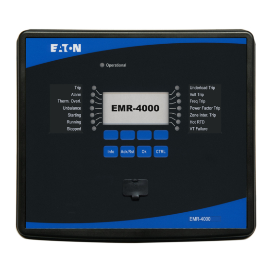
Page 129: Front Panel
EMR-4000 IM02602009E Front Panel The following illustration applies to protective devices with a small display: Programmable LEDs LED »System OK« Display Programmable LEDs Protective Device Softkeys OK-key Control INFO Key ACK/RST-key RS232 Interface (Signals/Messages) Connection) PowerPort-E www.eaton.com... - Page 130 EMR-4000 IM02602009E The following illustration applies to protective devices with a large display: Programmable LEDs LED »System OK« Display Programmable LEDs Protective Device Softkeys RS232 Interface INFO Key Control ACK/RST-key OK-key Connection) PowerPort-E (Signals/Messages) www.eaton.com...
- Page 131 EMR-4000 IM02602009E Item Graphic Name Description Group A: Basically, there are 14 Programmable programmable LEDs (7 on the LEDs left, 7 on the right side)provided for User to configure. The choice for each programmable LED can be any signal from the...
- Page 132 EMR-4000 IM02602009E Item Graphic Name Description Group B: Basically, there are 14 Programmable programmable LEDs (7 on the LEDs left, 7 on the right side)provided for User to configure. The choice for each programmable LED can be any signal from the...
- Page 133 EMR-4000 IM02602009E Item Graphic Name Description INFO Key Looking through the present (Signals/Messages LED assignment. The Direct Select key can be activated at any time. If the INFO key is actuated again, the User will leave the LED menu. Here only the first assignments of the LEDs will be shown.
- Page 134 EMR-4000 IM02602009E Item Graphic Name Description Used to abort changes and to »ACK/RST- Key« acknowledge messages as well as resetting counters. In order to reset, press the Soft- key »Wrench« and enter the password. The User can exit the reset menu by pressing the Softkey »Arrow-left«...
-
Page 135: Basic Menu Control
EMR-4000 IM02602009E Basic Menu Control The graphic user interface is equivalent to a hierarchical structured menu tree. For access to the individual sub-menus, the »SOFTKEYS«/Navigation Keys are used. The function of the »SOFTKEYS« can be found near the bottom of the display. -
Page 136: Powerport-E Keyboard Commands
EMR-4000 IM02602009E Keyboard Commands PowerPort-E The User can control PowerPort-E alternatively by means of keyboard commands (instead of the mouse). Description Move up within the navigation tree or parameter list. á â Move down within the navigation tree or parameter list. -
Page 137: Powerport-E
EMR-4000 IM02602009E PowerPort-E PowerPort-E is software that is used to configure a device and read data from a device. PowerPort-E provides the following: Menu controlled parameter setting including validity checks; Off-line configuration of all relay types; Reading and evaluation of statistical data and measuring values;... -
Page 138: Installation Of Powerport-E
Finish the installation procedure by mouse click on the »Complete« button. If the suggested installation folder was chosen in the procedure above, the User can now call up the program via [Start > Programs > Eaton Relays> PowerPort-E]. Uninstalling PowerPort-E Via the [Start>System Control >Software] menu, the PowerPort-E application can be uninstalled from the computer. -
Page 139: Setting Up The Connection Pc - Device
EMR-4000 IM02602009E Setting up the Connection PC - Device Set up a Connection via a Serial Interface After installation of the software, the »Connection PC/Notebook to the Device« has to be initially configured so that the User is able to read device data or re-write them into the device by means of the PowerPort-E application. - Page 140 EMR-4000 IM02602009E Parameter Setting and Evaluation via Serial/RS232 Device Example Protective Relay RS232 PowerPort-E www.eaton.com...
- Page 141 If your PC/notebook does not have an RS-232 interface, an USB-/RS232-Adapter+Null Modem Cable can be used. Only an adapter approved by Eaton Corporation may be used. First install the adapter (with the related driver that you can find on the CD) and then establish the connection (PowerPort-E =>...
- Page 142 EMR-4000 IM02602009E Set-up a Connection Via Ethernet - TCP/IP Warning: Mixing up IP Addresses (In case there is more than one protective device within the TCP/IP network or establishing an unintentional wrong connection to a protective device based on a wrong entered IP address.
- Page 143 EMR-4000 IM02602009E PowerPort-E TCP/IP Device Example Parameter Setting and Evaluation via TCP/IP www.eaton.com...
- Page 144 EMR-4000 IM02602009E PowerPort-E TCP/IP Ethernet TCP/IP TCP/IP TCP/IP Protective Protective Relay Relay Device Device Device Example Example Example Parameter Setting and Evaluation via TCP/IP www.eaton.com...
- Page 145 EMR-4000 IM02602009E Set-up a Connection Via Modbus Tunnel Establishing a connection via a Gateway (TCP/IP)/Modbus RTU to the device is only possible if your device is equipped with an Ethernet Interface (RJ45). Contact your IT administrator in order to establish the network connection.
- Page 146 EMR-4000 IM02602009E PowerPort-E TCP/IP Power Xpert Gateway IP-Address Modbus RTU Modbus RTU Modbus RTU Protective Protective Relay Relay Device Device Device Example Example Example Parameter Setting and Evaluation via Modbus Tunnel www.eaton.com...
- Page 147 Call up the menu »Internet options«. Call up the tab »Connections«. Click with the left hand mouse key on the button »Settings« on the right of the »Eaton Relays Direct Connection«. Set the check box »Use Proxy Server for this connection.
- Page 148 If a firewall is installed on your computer, TCP/IP port 52152 must have been released. If your computer does not have a serial interface, the User needs a USB-to-serial-adapter , approved by Eaton Corporation. This adapter has to be properly installed.
- Page 149 Call up the »Control Panel«. Choose »Network & Internet«. On the left side, click on »Manage Network Connections«. Right click on »Eaton Relays Direct Connection«. Choose »Delete« from the shortcut menu. Click on the »OK« button. Remove the (Virtual) Modem.
-
Page 150: Loading Of Device Data When Using Powerport-E
EMR-4000 IM02602009E Loading of Device Data When Using PowerPort-E Start the PowerPort-E application . Make sure the connection has been established properly. Connect your PC with the device via a null modem cable . Select »Receiving Data From The Device« in the »Device« menu. -
Page 151: Backup And Documentation When Using Powerport-E
EMR-4000 IM02602009E In order to (re-)transfer changed parameters into the device, select »Transfer all parameters into the device« in the »Device« menu. Confirm the safety inquiry »Shall the parameters be overwritten into the device?«. Enter the password for setting parameters in the pop-up window. - Page 152 EMR-4000 IM02602009E Printing of all opened working windows: The data shown on all windows are printed (i.e.: this applies only if more than one window is opened). Printing of the device parameter tree as from a shown position on: All data and parameters of the device parameter tree are printed as from the position/marking in the navigation window.
-
Page 153: Off-Line Device Planning Via Powerport-E
EMR-4000 IM02602009E Off-line Device Planning Via PowerPort-E In order to be able to transmit a parameter file (e.g.: created off-line) into the device, the following information must be located: Type code (written on the top of the device/type label); and Version of the device model (can be found in menu [Device Parameters\Version]. -
Page 154: Powerport-E Keyboard Commands
EMR-4000 IM02602009E PowerPort-E Keyboard Commands You can control PowerPort-E alternatively by means of keyboard commands (instead of the mouse) Description Moving up within the navigation tree or parameter list. á â Moving down within the navigation tree or parameter list. -
Page 155: Measuring Values
EMR-4000 IM02602009E Measuring Values Read Out Measured Values In the »Operation/Measured Values« menu, both measured and calculated values can be viewed. The measured values are ordered by »Standard values« and »Special values« (depending on the type of device). Read Out of Measured Values Via PowerPort-E If PowerPort-E is not running, please start the application. - Page 156 EMR-4000 IM02602009E HMI and PowerPort-E : Power Auto Scaling kW, kVAr or kVA MW, MVAr or MVA GW, GVAr or GVA www.eaton.com...
- Page 157 EMR-4000 IM02602009E Energy Units (applies only for devices with energy measurement) By means of the parameter » Energy Units« the User can determine how measured values are to be displayed within the HMI and PowerPort-E : Energy Auto Scaling kWh, kVArh or kVAh...
-
Page 158: Current - Measured Values
EMR-4000 IM02602009E Current - Measured Values If the device is not equipped with an voltage measuring card the first measuring input on the first current measuring card (slot with the lowest number) will be used as the reference angle (» IA«). - Page 159 EMR-4000 IM02602009E Value Description Menu path Angle IC Measured Value (Calculated): Angle of Phasor IC [Operation /Measured Values /Current Fund.] Angle IX meas Measured Value (Calculated): Angle of Phasor IX meas [Operation /Measured Values /Current Fund.] Angle IR calc Measured Value (Calculated): Angle of Phasor IR calc...
- Page 160 EMR-4000 IM02602009E Value Description Menu path %IB THD Measured Value (Calculated): IB Total Harmonic Distortion [Operation /Measured Values /Current RMS] %IC THD Measured Value (Calculated): IC Total Harmonic Distortion [Operation /Measured Values /Current RMS] IA THD Measured Value (Calculated): IA Total Harmonic Current...
-
Page 161: Voltage - Measured Values
EMR-4000 IM02602009E Voltage - Measured Values The first measuring input on the first measuring card (slot with the lowest number) is used as the reference angle. E.g. » VA« respectively » VAB« . Value Description Menu path Measured Value: Frequency... - Page 162 EMR-4000 IM02602009E Value Description Menu path V1 Fund. Measured value (calculated): Symmetrical components positive [Operation phase sequence voltage(Fundamental) /Measured Values /Voltage Fund.] V2 Fund. Measured value (calculated): Symmetrical components negative [Operation phase sequence voltage(Fundamental) /Measured Values /Voltage Fund.] VAB RMS...
- Page 163 EMR-4000 IM02602009E Value Description Menu path Angle VCA Measured Value (Calculated): Angle of Phasor VCA [Operation /Measured Values /Voltage Fund.] Angle VA Measured Value (Calculated): Angle of Phasor VA [Operation /Measured Values /Voltage Fund.] Angle VB Measured Value (Calculated): Angle of Phasor VB...
- Page 164 EMR-4000 IM02602009E Value Description Menu path %VCA THD Measured value (calculated): VCA Total Harmonic Distortion / [Operation fundamental /Measured Values /Voltage RMS] %VA THD Measured value (calculated): VA Total Harmonic Distortion / [Operation fundamental /Measured Values /Voltage RMS] %VB THD...
-
Page 165: Power - Measured Values
EMR-4000 IM02602009E Power - Measured Values Value Description Menu path Disp PF Measured Value (Calculated): 55D - Displacement Power Factor [Operation /Measured Values /Power] Wh Fwd Positive Active Power is consumed active energy [Operation /Measured Values /Energy] Wh Rev Negative Active Power (Fed Energy) - Page 166 EMR-4000 IM02602009E Value Description Menu path Syst VAr Fund. Measured VARs. Reactive power (Q- = Fed Reactive Power, Q+ = [Operation Consumpted Reactive Power) (Fundamental) /Measured Values /Power] Apt PF Measured Value (Calculated): 55A - Apparent Power Factor [Operation /Measured Values /Power] www.eaton.com...
-
Page 167: Energy Counter
EMR-4000 IM02602009E Energy Counter Global Parameters of the Energy Counter Module Parameter Description Setting range Default Menu path Power Units Power Units Power Auto Scaling, Power Auto [Operation Scaling kW/kVAr/kVA, /General Settings] MW/MVAr/MVA, GW/GVAr/GVA Energy Units Energy Units Energy Auto Sca-... - Page 168 EMR-4000 IM02602009E Signal Description Wh Rev Res Cr Signal: Wh Rev Reset Counter VArh Net Res Cr Signal: VArh Net Reset Counter VArh Lag Res Cr Signal: VArh Lag Reset Counter VArh Lead Res Cr Signal: VArh Lead Reset Counter...
-
Page 169: Statistics
EMR-4000 IM02602009E Statistics Statistics In menu »Operation/Statistics« the min., max. and mean values of the measured and calculated measured quantities can be found. Configuration of the Minimum and Maximum Values The calculation of the minimum and maximum values will be started:... -
Page 170: Configuration Of The Average Value Calculation
EMR-4000 IM02602009E Configuration of the Average Value Calculation Configuration of the Current Based Average Value Calculation* *=Availability depends on the ordered device code. Current based Average Values and Peak Values Time period for the Reset of the average and Start options... - Page 171 EMR-4000 IM02602009E Configuration of the Voltage Based Average Value Calculation* *=Availability depends on the ordered device code. Voltage based Average Values Time period for the Reset of the average and Start options calculation of the peak values average values Configuration Options...
-
Page 172: Direct Commands
EMR-4000 IM02602009E Direct Commands Parameter Description Setting range Default Menu path ResFc all Resetting of all Statistic values (Current Demand, Power Inactive, Inactive [Operation Demand, Min, Max) Active /Reset /Flags] ResFc I Demand Resetting of Statistics - Current Demand (avg, peak avg) Inactive,... - Page 173 EMR-4000 IM02602009E Parameter Description Setting range Default Menu path Start I Demand Fc Start of the calculation, if the assigned signal becomes 1..n, Assignment [Device Para true. List /Statistics Only available if: Start I Demand via: = StartFct /Demand /Current Demand] ResFc I Demand Resetting of Statistics - Current Demand (avg, peak avg) 1..n, Assignment...
- Page 174 EMR-4000 IM02602009E Parameter Description Setting range Default Menu path Start P Demand Fc Start of the calculation, if the assigned signal becomes 1..n, Assignment [Device Para true. List /Statistics Only available if: Start P Demand via: = StartFct /Demand /Power Demand]...
-
Page 175: States Of The Inputs Of The Statistics Module
EMR-4000 IM02602009E States of the Inputs of the Statistics Module Name Description Assignment via StartFc I Demand-I State of the module input: Start of Statistics of the Current Demand [Device Para (Update the displayed Demand ) /Statistics /Demand /Current Demand]... -
Page 176: Signals Of The Statistics Module
EMR-4000 IM02602009E Signals of the Statistics Module Signal Description ResFc all Signal: Resetting of all Statistic values (Current Demand, Power Demand, Min, Max) ResFc I Demand Signal: Resetting of Statistics - Current Demand (avg, peak avg) ResFc P Demand Signal: Resetting of Statistics - Power Demand (avg, peak avg) - Page 177 EMR-4000 IM02602009E Current - Statistic Values Value Description Menu path I1 max Fund. Maximum value positive phase sequence current (Fundamental) [Operation /Statistics /Max /CT] I1 min Fund. Minimum value positive phase sequence current (Fundamental) [Operation /Statistics /Min /CT] I2 max Fund.
- Page 178 EMR-4000 IM02602009E Value Description Menu path IB avg RMS IB average value (RMS) [Operation /Statistics /Demand /Current Demand] IB min RMS IB minimum value (RMS) [Operation /Statistics /Min /CT] IC max RMS IC maximum value (RMS) [Operation /Statistics /Max /CT]...
- Page 179 EMR-4000 IM02602009E Value Description Menu path %(I2/I1) max Measured value (calculated): I2/I1 maximum value, phase sequence [Operation will be taken into account automatically /Statistics /Max /CT] %(I2/I1) min Measured value (calculated): I2/I1 minimum value, phase sequence [Operation will be taken into account automatically...
- Page 180 EMR-4000 IM02602009E Voltage - Statistic Values Value Description Menu path f max Max. frequency value [Operation /Statistics /Max /Voltage] f min Min. frequency value [Operation /Statistics /Min /Voltage] V1 max Fund. Maximum value: Symmetrical components positive phase sequence [Operation voltage(Fundamental)
- Page 181 EMR-4000 IM02602009E Value Description Menu path VBC max RMS VBC maximum value (RMS) [Operation /Statistics /Max /Voltage] VBC min RMS VBC minimum value (RMS) [Operation /Statistics /Min /Voltage] VCA max RMS VCA maximum value (RMS) [Operation /Statistics /Max /Voltage] VCA min RMS...
- Page 182 EMR-4000 IM02602009E Value Description Menu path VC min RMS VC minimum value (RMS) [Operation /Statistics /Min /Voltage] VX meas max RMS Measured value: VX maximum value (RMS) [Operation /Statistics /Max /Voltage] VX meas min RMS Measured value: VX minimum value (RMS)
- Page 183 EMR-4000 IM02602009E Power - Statistic Values Value Description Menu path Disp PF max Maximum value of the 55D - Displacement Power Factor [Operation /Statistics /Max /Power] Disp PF min Minimum value of the 55D - Displacement Power Factor [Operation /Statistics...
- Page 184 EMR-4000 IM02602009E Value Description Menu path Syst VAr max Maximum value of the reactive power [Operation /Statistics /Max /Power] Syst VAr avg Average of the reactive power [Operation /Statistics /Demand /Power Demand] Syst VAr min Minimum value of the reactive power...
-
Page 185: System Alarms
EMR-4000 IM02602009E System Alarms Available Elements: SysA Within the System Alarms menu [SysA] the User can configure: General Settings (activate/inactivate the Demand Management, optional assign a signal, that will block the Demand Management); Power Protection (please refer to section 32, 32V, 32VA);... - Page 186 EMR-4000 IM02602009E Select a time base for the » window« . Determine if the window is » fixed« or » sliding «. The interval time (window) can be set to fixed or sliding. Example for a fixed window: If the range is set for 15 minutes, the protective device calculates the average current or power over the past 15 minutes and updates the value every 15 minutes.
- Page 187 EMR-4000 IM02602009E Window configuration = Sliding Duration t-Delay Average Calculation Pickup Sliding t-Delay Average Calculation Pickup Sliding t-Delay Average Calculation Pickup Window configuration = Fixed Average Calculation Average Calculation Average Calculation Average Calculation Duration Duration Duration Average Calculation Average Calculation...
-
Page 188: Peak Demand
EMR-4000 IM02602009E Step 2. In addition, the Demand specific settings have to be configured in the [System Para/System Alarms/Demand] menu: Determine if the demand should generate an alarm or if it should run in the silent mode (Alarm active/inactive); Set the threshold; and Where applicable, set a delay time for the alarm. -
Page 189: Device Planning Parameters Of The Demand Management
EMR-4000 IM02602009E Device Planning Parameters of the Demand Management Parameter Description Options Default Menu path Mode Mode Do not use, [Device Planning] Signals of the Demand Management (States of the Outputs) Signal Description Active Signal: Active ExBlo Signal: External Blocking... -
Page 190: Global Protection Parameter Of The Demand Management
EMR-4000 IM02602009E Global Protection Parameter of the Demand Management Parameter Description Setting range Default Menu path Function Permanent activation or deactivation of module/element. Inactive, Inactive [SysA Active /General Settings] ExBlo Fc Activate (allow) or inactivate (disallow) blocking of the 1..n, Assignment [SysA module/element. - Page 191 EMR-4000 IM02602009E Parameter Description Setting range Default Menu path Threshold Threshold (to be entered as primary value) 1 - 40000000kVA 10000kVA [SysA /Power /VA] t-Delay Tripping Delay 0 - 60min 0min [SysA /Power /VA] Alarm Alarm Inactive, Inactive [SysA Active...
- Page 192 EMR-4000 IM02602009E Parameter Description Setting range Default Menu path Threshold Threshold (to be entered as primary value) 1 - 40000000kVA 20000kVA [SysA /Demand /Power Demand /VA Demand] t-Delay Tripping Delay 0 - 60min 0min [SysA /Demand /Power Demand /VA Demand]...
- Page 193 EMR-4000 IM02602009E Parameter Description Setting range Default Menu path t-Delay Tripping Delay 0 - 3600s [SysA /THD /V THD] www.eaton.com...
-
Page 194: States Of The Inputs Of The Demand Management
EMR-4000 IM02602009E States of the Inputs of the Demand Management Name Description Assignment via ExBlo-I Module Input State: External Blocking [SysA /General Settings] www.eaton.com... -
Page 195: Resets
EMR-4000 IM02602009E Resets Collective Acknowledgments for Latched Signals: Collective Acknowledgments LEDs Relay Outputs SCADA Pending LEDs+ Trip Command Relay Outputs+ SCADA+ Pending Trip Command All LEDs at once: All Relay Outputs All SCADA signals All pending trip All at once:... - Page 196 EMR-4000 IM02602009E Options for Individual Acknowledgments for Latched Signals: Individual Acknowledgment LEDs Relay Output Pending Trip Command Via a signal from the Single LED: Relay Output: Pending Trip Command. assignment list (e.g.: a Where? digital Input), a single ... can...
-
Page 197: Manual Acknowledgment
EMR-4000 IM02602009E Manual Acknowledgment Press the »Ack/Rst« button on the panel. • Select the item to be acknowledged via the softkeys: • Relay Outputs; • LEDs; • SCADA; • A trip command; or • All the above mentioned items at once. -
Page 198: External Acknowledgments
EMR-4000 IM02602009E External Acknowledgments Within the [Ex Acknowledge] menu, the User can assign a signal (e.g.: the state of a digital input) from the assignment list that: Acknowledges all (acknowledgeable) LEDs at once; • Acknowledges all (acknowledgeable) Output Relays at once; or •... -
Page 199: External Led - Acknowledgment Signals
EMR-4000 IM02602009E External LED - Acknowledgment Signals The following signals can be used for external acknowledgment of latched LEDs. Name Description No assignment DI-8P X1.DI 1 Signal: Digital Input DI-8P X1.DI 2 Signal: Digital Input DI-8P X1.DI 3 Signal: Digital Input DI-8P X1.DI 4... - Page 200 EMR-4000 IM02602009E Name Description Logic.LE3.Gate Out Signal: Output of the logic gate Logic.LE3.Timer Out Signal: Timer Output Logic.LE3.Out Signal: Latched Output (Q) Logic.LE3.Out inverted Signal: Negated Latched Output (Q NOT) Logic.LE4.Gate Out Signal: Output of the logic gate Logic.LE4.Timer Out Signal: Timer Output Logic.LE4.Out...
- Page 201 EMR-4000 IM02602009E Name Description Logic.LE12.Timer Out Signal: Timer Output Logic.LE12.Out Signal: Latched Output (Q) Logic.LE12.Out inverted Signal: Negated Latched Output (Q NOT) Logic.LE13.Gate Out Signal: Output of the logic gate Logic.LE13.Timer Out Signal: Timer Output Logic.LE13.Out Signal: Latched Output (Q) Logic.LE13.Out inverted...
- Page 202 EMR-4000 IM02602009E Name Description Logic.LE21.Out Signal: Latched Output (Q) Logic.LE21.Out inverted Signal: Negated Latched Output (Q NOT) Logic.LE22.Gate Out Signal: Output of the logic gate Logic.LE22.Timer Out Signal: Timer Output Logic.LE22.Out Signal: Latched Output (Q) Logic.LE22.Out inverted Signal: Negated Latched Output (Q NOT) Logic.LE23.Gate Out...
- Page 203 EMR-4000 IM02602009E Name Description Logic.LE30.Out inverted Signal: Negated Latched Output (Q NOT) Logic.LE31.Gate Out Signal: Output of the logic gate Logic.LE31.Timer Out Signal: Timer Output Logic.LE31.Out Signal: Latched Output (Q) Logic.LE31.Out inverted Signal: Negated Latched Output (Q NOT) Logic.LE32.Gate Out Signal: Output of the logic gate Logic.LE32.Timer Out...
- Page 204 EMR-4000 IM02602009E Name Description Logic.LE40.Gate Out Signal: Output of the logic gate Logic.LE40.Timer Out Signal: Timer Output Logic.LE40.Out Signal: Latched Output (Q) Logic.LE40.Out inverted Signal: Negated Latched Output (Q NOT) Logic.LE41.Gate Out Signal: Output of the logic gate Logic.LE41.Timer Out Signal: Timer Output Logic.LE41.Out...
- Page 205 EMR-4000 IM02602009E Name Description Logic.LE49.Timer Out Signal: Timer Output Logic.LE49.Out Signal: Latched Output (Q) Logic.LE49.Out inverted Signal: Negated Latched Output (Q NOT) Logic.LE50.Gate Out Signal: Output of the logic gate Logic.LE50.Timer Out Signal: Timer Output Logic.LE50.Out Signal: Latched Output (Q) Logic.LE50.Out inverted...
- Page 206 EMR-4000 IM02602009E Name Description Logic.LE58.Out Signal: Latched Output (Q) Logic.LE58.Out inverted Signal: Negated Latched Output (Q NOT) Logic.LE59.Gate Out Signal: Output of the logic gate Logic.LE59.Timer Out Signal: Timer Output Logic.LE59.Out Signal: Latched Output (Q) Logic.LE59.Out inverted Signal: Negated Latched Output (Q NOT) Logic.LE60.Gate Out...
- Page 207 EMR-4000 IM02602009E Name Description Logic.LE67.Out inverted Signal: Negated Latched Output (Q NOT) Logic.LE68.Gate Out Signal: Output of the logic gate Logic.LE68.Timer Out Signal: Timer Output Logic.LE68.Out Signal: Latched Output (Q) Logic.LE68.Out inverted Signal: Negated Latched Output (Q NOT) Logic.LE69.Gate Out Signal: Output of the logic gate Logic.LE69.Timer Out...
- Page 208 EMR-4000 IM02602009E Name Description Logic.LE77.Gate Out Signal: Output of the logic gate Logic.LE77.Timer Out Signal: Timer Output Logic.LE77.Out Signal: Latched Output (Q) Logic.LE77.Out inverted Signal: Negated Latched Output (Q NOT) Logic.LE78.Gate Out Signal: Output of the logic gate Logic.LE78.Timer Out Signal: Timer Output Logic.LE78.Out...
-
Page 209: Manual Resets
EMR-4000 IM02602009E Manual Resets In the »Operation/Reset« menu, the User can: Reset counters; • Delete records (e.g.: waveform records); and • Reset special things (like statistics, thermal replica, etc.). • The description of the reset commands can be found within the corresponding modules. -
Page 210: Status Display
EMR-4000 IM02602009E Status Display In the status display within the »Operation« menu, the present state of all signals can be viewed. This means the User is able to see if the individual signals are active or inactive at that moment. The User can see all signals sorted by protective elements/modules. -
Page 211: Operating Panel (Hmi)
EMR-4000 IM02602009E Operating Panel (HMI) Special Parameters of the Panel The »Device Parameter/HMI« menu is used to define the contrast of the display, the maximum admissible edit time, and the menu language (after expiration, all unsaved parameter changes will be rejected). -
Page 212: Recorders
EMR-4000 IM02602009E Recorders Waveform Recorder Waveform rec The waveform recorder works with 32 samples per cycle. It can be started by one of eight start events (selection from the »Assignment list«/OR-Logic). The waveform record contains the measuring values including the pre-trigger time. By means of PowerPort-E/Quality Manager (option), the oscillographic curves of the analog (current, voltage) and digital channels/traces can be shown and evaluated in a graphical form. - Page 213 EMR-4000 IM02602009E Start: 1 Trigger Start: 2 Trigger Start: 3 Trigger Start: 4 Trigger Recording Start: 5 Trigger Start: 6 Trigger Start: 7 Trigger Start: 8 Trigger Man. Trigger www.eaton.com...
- Page 214 EMR-4000 IM02602009E Start 1 = Prot.Pickup Start 2 = -.- Start 3 = -.- Start 4 = -.- Start 5 = -.- Start 6 = -.- Start 7 = -.- Start 8 = -.- Auto overwriting = Active Post-trigger time = 25%...
- Page 215 EMR-4000 IM02602009E Start 1 = Prot.Trip Start 2 = -.- Start 3 = -.- Start 4 = -.- Start 5 = -.- Start 6 = -.- Start 7 = -.- Start 8 = -.- t-rec < Max file size Auto overwriting = Active...
- Page 216 EMR-4000 IM02602009E Read Out of Waveform Records Within the »Operation/Waveform rec« menu, the User can: Detect the accumulated waveform records. • Within the »Operation/Recorders/Man Trigger« menu, the User can trigger the waveform recorder manually. To Read Out the Waveform Recorder with PowerPort-E If PowerPort-E is not running, please start the application.
- Page 217 EMR-4000 IM02602009E Deleting Waveform Records Within the »Operation/Waveform rec« menu, the User can: Delete waveform records; Choose the waveform record that is to be deleted via »SOFTKEY« »up« and »SOFTKEY« »down«; Call up the detailed view of the waveform record via »SOFTKEY« »right«;...
- Page 218 EMR-4000 IM02602009E Direct Commands of the Waveform Recorder Module Parameter Description Setting range Default Menu path Man. Trigger Manual Trigger False, False [Operation True /Recorders /Man. Trigger] Res all rec Reset all records Inactive, Inactive [Operation Active /Reset /Flags] Global Protection Parameters of the Waveform Recorder Module...
- Page 219 EMR-4000 IM02602009E Parameter Description Setting range Default Menu path Start: 7 Start recording if the assigned signal is true. 1..n, Assignment [Device Para List /Recorders /Waveform rec] Start: 8 Start recording if the assigned signal is true. 1..n, Assignment [Device Para...
- Page 220 EMR-4000 IM02602009E Waveform Recorder Module Input States Name Description Assignment via Start1-I State of the module input:: Trigger event / start recording if: [Device Para /Recorders /Waveform rec] Start2-I State of the module input:: Trigger event / start recording if:...
- Page 221 EMR-4000 IM02602009E Waveform Recorder Module Signals Signal Description Recording Signal: Recording Memory full Signal: Memory Full Clear fail Signal: Clear Failure in Memory Res all rec Signal: All records deleted Res record Signal: Delete Record Man. Trigger Signal: Manual Trigger...
- Page 222 EMR-4000 IM02602009E Special Parameters of the Waveform Recorder Value Description Default Size Menu path Rec state Recording state Ready Ready, [Operation Recording, /Status display Writing file, /Recorders Trigger Blo /Waveform rec] Error code Error code [Operation Write err, /Status display...
-
Page 223: Fault Recorder
EMR-4000 IM02602009E Fault Recorder Fault rec Purpose of the Fault recorder The Fault Recorder provides compressed information about faults (e.g. Trip Causes). The compressed information can be read out also at the HMI. This might be helpful for fast fault analysis already at the HMI. After a fault, a popup window will be sent onto the display in order to draw the users attention to the fault. - Page 224 EMR-4000 IM02602009E Definitions Time to Trip: Time between First Alarm (Prot.Pickup) and First Trip (Prot.Trip) decision Fault Duration: «) signal up to the falling Time period from the rising edge of the General Pickup (»P ICKUP edge of the General Pickup Signal. Please note that General Pickup is an or-connection (disjunction) of all Pickup signals.
- Page 225 EMR-4000 IM02602009E Behaviour of the Fault recorder Who triggers the Fault Recorder? The Fault Recorder will be triggered by the rising edge of the »P « (General Pickup) signal. Please note that ICKUP « (General Pickup) is an or-connection of all Pickup signals. The first Pickup will trigger the Fault recorder.
- Page 226 EMR-4000 IM02602009E By using Softkey »OK«. How to find out fast, if a fault has lead to a trip or not? Faults that lead to a trip will be indicated by a flash icon (right side) within the overview menu of the fault recorder.
- Page 227 EMR-4000 IM02602009E Content of a Fault Record A fault record comprises information about: Date/Time Date and Time of the Fault FaultNr The number of the fault will be incremented with each fault (General Alarm or »P «) ICKUP Grid Fault No.
- Page 228 EMR-4000 IM02602009E How to set up the Fault Recorder The » Record-Mode« will determine if trips only cause a fault record or if also Alarms without a consecutively trip should cause a fault record. This parameter is to be set within menu [Device Para\Recorders\Fault rec]...
- Page 229 EMR-4000 IM02602009E How to Read Out the Fault Recorder Via PowerPort-E If PowerPort-E is not running, please start the application. If the device data have not been loaded, click »Receive Data From The Device« in the »Device« menu. Double click the »Operation« icon in the navigation tree.
- Page 230 EMR-4000 IM02602009E Direct Commands of the Fault Recorder Module Parameter Description Setting range Default Menu path Res all rec Reset all records Inactive, Inactive [Operation Active /Reset /Flags] Global Protection Parameters of the Fault Recorder Module Parameter Description Setting range...
- Page 231 EMR-4000 IM02602009E Fault Recorder Module Signals Signal Description Res record Signal: Delete Record www.eaton.com...
-
Page 232: Event Recorder
EMR-4000 IM02602009E Event Recorder Event rec The event recorder can register up to 300 events and the last 50 (minimum) saved events are stored in non-volatile memory, and therefore retained when power is lost to the unit. The following information is provided for any of the events. - Page 233 EMR-4000 IM02602009E Read Out the Event Recorder Call up the » main menu«. Call up the sub-menu »Operation/Recorders/Event rec« . Select an event. To Read Out the Event Recorder via PowerPort-E If PowerPort-E is not running, please start the application.
- Page 234 EMR-4000 IM02602009E Via the print menu, the User can export the data into a file. Please proceed as follows. •Call up the data as described above. •Call up the »File/Print« menu. •Choose »Print Actual Working Window« within the pop-up. •Press the »Print« button.
- Page 235 EMR-4000 IM02602009E Direct Commands of the Event Recorder Module Parameter Description Setting range Default Menu path Res all rec Reset all records Inactive, Inactive [Operation Active /Reset /Flags] Event Recorder Module Signals Signal Description Res all rec Signal: All records deleted...
-
Page 236: Trend Recorder
EMR-4000 IM02602009E Trend Recorder Available Elements: Trend rec Functional Description The Trend Data are data points stored by the Trend Recorder on the relay device over fixed intervals of time, and can be downloaded from the device using PowerPort-E. A Trend Record is viewable using the Quality Monitor software by selecting files saved by PowerPort-E with a file extension of “.ErTr”. - Page 237 EMR-4000 IM02602009E Selection List for Trending Name Description No assignment VT.VA RMS Measured value: Phase-to-neutral voltage (RMS) VT.VB RMS Measured value: Phase-to-neutral voltage (RMS) VT.VC RMS Measured value: Phase-to-neutral voltage (RMS) VT.VX meas RMS Measured value (measured): VX measured (RMS) VT.VAB RMS...
- Page 238 EMR-4000 IM02602009E Name Description CT.IA THD Measured Value (Calculated): IA Total Harmonic Current CT.IB THD Measured Value (Calculated): IB Total Harmonic Current CT.IC THD Measured Value (Calculated): IC Total Harmonic Current CT.%(I2/I1) Measured value (calculated): I2/I1, phase sequence will be taken into account automatically.
- Page 239 EMR-4000 IM02602009E Name Description ECr.Disp PF Measured Value (Calculated): 55D - Displacement Power Factor ECr.Apt PF Measured Value (Calculated): 55A - Apparent Power Factor ECr.VAh Net Net VA Hours www.eaton.com...
- Page 240 EMR-4000 IM02602009E Global Protection Parameters of the Trend Recorder Parameter Description Setting range Default Menu path Resolution Resolution (recording frequency) 60 min, 15 min [Device Para 30 min, /Recorders 15 min, /Trend rec] 10 min, 5 min Observed Value1 Observed Value1 1..n, TrendRecList...
- Page 241 EMR-4000 IM02602009E Parameter Description Setting range Default Menu path Observed Value10 Observed Value10 1..n, TrendRecList [Device Para /Recorders /Trend rec] www.eaton.com...
- Page 242 EMR-4000 IM02602009E Trend Recorder Module Signals (Output States) Signal Description Hand Reset Hand Reset Direct Commands of the Trend Recorder Parameter Description Setting range Default Menu path Reset Delete all entries Inactive, Inactive [Operation Active /Reset /Flags] Counter Values of the Trend Recorder...
-
Page 243: Motor Start Recorder
EMR-4000 IM02602009E Motor Start Recorder Available Elements: Start rec The Motor Start Recorder is accessed using PowerPort-E or via the front panel interface of the relay. This feature provides information recorded at the time of each start of the motor such as: Date of the motor start event;... - Page 244 EMR-4000 IM02602009E To permanently remove all start records within a device's start recorder, select the “Delete All Start Records” button also located in the upper left hand corner of the “Start Rec” window. This will remove all previously stored start records within the device to which the User is presently connected.
- Page 245 EMR-4000 IM02602009E Displaying Start Records When a Start Record is called up, a window with the following options pops up. View motor start data graphically in the Quality Manager software. In the Quality Manager software the User can view the RMS value of the phase currents, thermal capacity used, and temperatures measured by the URTD module if a URTD is installed and attached to the relay.
- Page 246 EMR-4000 IM02602009E Global Protection Parameters of the Motor Start Recorder Parameter Description Setting range Default Menu path Resolution Resolution (recording frequency) 50ms, 50ms [Device Para 100ms, /Recorders /Start rec] www.eaton.com...
- Page 247 EMR-4000 IM02602009E Motor Start Recorder Module Signals (Output States) Signal Description Storing Signal: Data are saved www.eaton.com...
- Page 248 EMR-4000 IM02602009E Direct Commands of the Motor Start Recorder Module Parameter Description Setting range Default Menu path Res StartRec Delete all start recorder records Inactive, Inactive [Operation Active /Reset /Flags] Res StatisticRec Delete all statistic recorder records (start trending) Inactive,...
-
Page 249: Statistic Recorder
EMR-4000 IM02602009E Statistic Recorder The Statistic Recorder shows motor specific statistical data on a monthly base. The Statistic Recorder can record up to 24 monthly reports. The reports are power fail safe stored. In order to view information from the Statistic Recorder, the User has to select [Operation/Recorder/Statisticrec] from the menu tree. -
Page 250: History Function
EMR-4000 IM02602009E History Function The History function, accessible under the Operations menu, can be utilized as a counter or log of specific occurrences monitored by the device. The types of occurrence that can be recorded include: Operations (OperationsCr); • Alarms (AlarmCr);... -
Page 251: Time Synchronization
EMR-4000 IM02602009E Time Synchronization TimeZones The device gives the User the ability to synchronize the device with a central time generator. This provides the following advantages: The time does not drift from the reference time. A continuously accumulating deviation of the reference time thereby will be balanced. -
Page 252: Accuracy Of Time Synchronization
EMR-4000 IM02602009E Accuracy of Time Synchronization The accuracy of the device's synchronized system time depends on different factors: Accuracy of the connected time generator; Synchronization protocol that is used; and At Modbus TCP and SNTP: Network load and data package transmission times Please consider the accuracy of the time generator used. - Page 253 EMR-4000 IM02602009E Selection of Timezone and Synchronisation Protocol The protection relay masters both UTC and local time. This means that the device can be synchronised with UTC time while using local time for user display. Time Synchronisation with UTC time (recommended): Time synchronisation is usually done using UTC time.
- Page 254 EMR-4000 IM02602009E Global Protection Parameters of the Time Synchronization Parameter Description Setting range Default Menu path DST offset Difference to wintertime -180 - 180min 60min [Device Para /Time /Timezone] DST manual Manual setting of the Daylight Saving Time Inactive, Active...
- Page 255 EMR-4000 IM02602009E Parameter Description Setting range Default Menu path Summertime w Place of selected day in month (for clock change First, Last [Device Para summertime) Second, /Time Only available if: DST manual = Active Third, /Timezone] Fourth, Last Summertime h...
- Page 256 EMR-4000 IM02602009E Parameter Description Setting range Default Menu path Wintertime h Hour of clock change wintertime 0 - 23h [Device Para /Time Only available if: DST manual = Active /Timezone] Wintertime min Minute of clock change wintertime 0 - 59min...
- Page 257 EMR-4000 IM02602009E Parameter Description Setting range Default Menu path Time Zones Time Zones UTC+14 Kiritimati, UTC+0 London [Device Para UTC+13 Rawaki, /Time UTC+12.75 Chat- /Timezone] ham Island, UTC+12 Wellington, UTC+11.5 Kingston, UTC+11 Port Vila, UTC+10.5 Lord Howe Island, UTC+10 Sydney, UTC+9.5 Adelaide,...
- Page 258 EMR-4000 IM02602009E Parameter Description Setting range Default Menu path TimeSync Time synchronization [Device Para IRIG-B, /Time SNTP, /TimeSync Modbus /TimeSync] www.eaton.com...
-
Page 259: Sntp
EMR-4000 IM02602009E SNTP SNTP Important pre-condition: The device needs to have access to an SNTP server via the connected network. This server preferably should be installed locally. Principle – General Use SNTP is a standard protocol for time synchronization via a network. At minimum, one SNTP server has to be integrated into the network. - Page 260 EMR-4000 IM02602009E Accuracy The accuracy of the SNTP server used and the accuracy of its reference clock influences the accuracy of the protection relay's clock. With each transmitted time information, the SNTP server sends information about its accuracy: Stratum: The stratum gives information on how close the SNTP server within the cluster is to other NTP servers that are connected to an atomic clock.
- Page 261 EMR-4000 IM02602009E Fault Analysis If there is no SNTP signal for more than 120 seconds., the SNTP status changes from “active” to “inactive” and an entry in the Event Recorder will be set. The SNTP functionality can be checked in the [Operation/Status Display/Time Sync./Sntp] menu.
- Page 262 EMR-4000 IM02602009E Device Planning Parameters of the SNTP Parameter Description Options Default Menu path Mode Mode Do not use, [Device Planning] Direct Commands of the SNTP Parameter Description Setting range Default Menu path Res Counter Reset all Counters. Inactive, Inactive...
- Page 263 EMR-4000 IM02602009E Parameter Description Setting range Default Menu path IP Byte4 IP1.IP2.IP3.IP4 0 - 255 [Device Para /Time /TimeSync /SNTP] Server2 Server 2 Inactive, Inactive [Device Para Active /Time /TimeSync /SNTP] IP Byte1 IP1.IP2.IP3.IP4 0 - 255 [Device Para /Time...
- Page 264 EMR-4000 IM02602009E Signals of the SNTP Signal Description SNTP active Signal: If there is no valid SNTP signal for 120 sec, SNTP is regarded as inactive. SNTP Counters Value Description Default Size Menu path NoOfSyncs Total Number of Synchronizations. 0 - 9999999999...
- Page 265 EMR-4000 IM02602009E Value Description Default Size Menu path NoOfHighOffs Service counter: Total Number of high Offsets. 0 - 9999999999 [Operation /Count and RevData /TimeSync /SNTP] NoOfIntTimeouts Service counter: Total Number of internal 0 - 9999999999 [Operation timeouts. /Count and RevData...
- Page 266 EMR-4000 IM02602009E Value Description Default Size Menu path NetConn Quality of Network Connection (GOOD, GOOD, [Operation SUFFICIENT, BAD). SUFFICENT, /Status display BAD, /TimeSync /SNTP] www.eaton.com...
-
Page 267: Irig-B00X
EMR-4000 IM02602009E IRIG-B00X IRIG-B Requirement: An IRIG-B00X time code generator is needed. IRIG-B004 and higher will support/transmit the “year information”. If you are using an IRIG time code that does not support the “year information” (IRIG-B000, IRIG-B001, IRIG-B002, IRIG-B003), you have to set the “year”... - Page 268 EMR-4000 IM02602009E IRIG-B Commissioning Activate the IRIG-B synchronization within menu [Device Para/ Time/ TimeSync]: Select » IRIG-B« in the time synchronisation menu. Set the time synchronization in the IRIG-B menu to » Active« . Select the IRIG-B type (choose B000 through B007).
- Page 269 EMR-4000 IM02602009E Device Planning Parameters of the IRIG-B00X Parameter Description Options Default Menu path Mode Mode Do not use, [Device Planning] Direct Commands of the IRIG-B00X Parameter Description Setting range Default Menu path Res IRIG-B Cr Resetting of the Diagnosis Counters: IRIG-B...
- Page 270 EMR-4000 IM02602009E Signals of the IRIG-B00X (Output States) Signal Description Active Signal: Active Inverted Signal: IRIG-B inverted Control Signal1 Signal: IRIG-B Control Signal Control Signal2 Signal: IRIG-B Control Signal Control Signal4 Signal: IRIG-B Control Signal Control Signal5 Signal: IRIG-B Control Signal...
- Page 271 EMR-4000 IM02602009E Value Description Default Size Menu path Edges Edges 0 - 65535 [Operation /Count and RevData /TimeSync /IRIG-B] www.eaton.com...
-
Page 272: Device Parameters
EMR-4000 IM02602009E Device Parameters Date and Time In the »Device parameters/Date/Time« menu, the User can set the date and time. The User cannot set time and date manually (manual changes will be ignored), if the clock of the protective device is synchronized automatically (e.g. via IRIG- B or SNTP). -
Page 273: Tcp/Ip Settings
EMR-4000 IM02602009E TCP/IP Settings Warning: Mixing up IP Addresses (In case there is more than one protective device within the TCP/IP network or establishing an unintentional wrong connection to a protective device based on a wrong entered IP address. Transferring parameters into the wrong protective device might lead to death, personal injury, or damage of electrical equipment. -
Page 274: Direct Commands Of The System Module
EMR-4000 IM02602009E Direct Commands of the System Module Parameter Description Setting range Default Menu path Ack RO LED Comm Reset the Relay Outputs, LEDs, Communication, and the Inactive, Inactive [Operation TCmd Trip Command. Active /Reset /Flags] Ack LED All acknowledgeable LEDs will be acknowledged. - Page 275 EMR-4000 IM02602009E Parameter Description Setting range Default Menu path MaintMode Arc Flash Reduction Maintenance Switch Mode: Manual Maint Mode inacti- Inactive [Service Manually Activation of the Arc Flash Reduction Mode /MaintMode Activation via Manually] Only available if: Maint Mode = Activation Manually...
-
Page 276: Global Protection Parameters Of The System
EMR-4000 IM02602009E Global Protection Parameters of the System Parameter Description Setting range Default Menu path PSet-Switch Switching Parameter Set PS1, PSS via Inp fct [Protection Para PS2, /PSet-Switch] PS3, PS4, PSS via Inp fct, PSS via Comm PS1: Activated by This Setting Group will be the active one if: The 1..n, PSS... - Page 277 EMR-4000 IM02602009E Parameter Description Setting range Default Menu path Remote Reset Enables or disables the option to acknowledge from Inactive, Active [Device Para external/remote via signals (assignments) and Active /Ex Acknowledge] Communication. Ack LED All acknowledgeable LEDs will be acknowledged if the 1..n, LEDAcknList...
-
Page 278: System Module Input States
EMR-4000 IM02602009E System Module Input States Name Description Assignment via Ack LED-I Module Input State: LEDs Acknowledgment by Digital Input. [Device Para /Ex Acknowledge] Ack RO-I Module Input State: Acknowledgment of the Relay Outputs. [Device Para /Ex Acknowledge] Ack Comm-I Module Input State: Acknowledge Communication via Digital Input. - Page 279 EMR-4000 IM02602009E Signal Description Maint Mode Active Signal: Arc Flash Reduction Maintenance Active Maint Mode Inactive Signal: Arc Flash Reduction Maintenance Inactive MaintMode Manually Signal: Arc Flash Reduction Maintenance Manual Mode Maint Mode Comm Signal: Arc Flash Reduction Maintenance Comm Mode...
-
Page 280: Special Values Of The System Module
EMR-4000 IM02602009E Special Values of the System Module Value Description Menu path Build Build [Device Para /Version] Version Version [Device Para /Version] Operating hours Cr Operating hours counter of the protective device [Operation /Count and RevData /Sys] Hours Counter Resettable device operation hours counter... -
Page 281: Communication Protocols
EMR-4000 IM02602009E Communication Protocols Modbus ® Modbus Modbus Protocol Configuration ® The time-controlled Modbus protocol is based on the master-slave working principle. This means that the substation ® control and protection system sends an inquiry or instruction to a certain device (slave address) that will then be answered or carried out accordingly. - Page 282 EMR-4000 IM02602009E Modbus RTU Part 1: Configuration of the Devices Call up »Device parameter/Modbus« and set the following communication parameters: Slave address, to allow clear identification of the device; and Baud rate. Also, select the RS485 interface-related parameters such as: Number of data bits;...
- Page 283 EMR-4000 IM02602009E Modbus TCP Establishing a connection via TCP/IP to the device is only possible if the device is equipped with an Ethernet Interface (RJ45). Contact your IT administrator in order to establish the network connection. Part 1: Setting the TCP/IP Parameters Call up »Device parameter/TCP/IP«...
- Page 284 EMR-4000 IM02602009E Direct Commands of the Modbus ® Parameter Description Setting range Default Menu path Res Diagn Cr All Modbus Diagnosis Counters will be reset. Inactive, Inactive [Operation Active /Reset /Counter] Global Protection Parameters of the Modbus ® Parameter Description...
- Page 285 EMR-4000 IM02602009E Parameter Description Setting range Default Menu path Physical Settings Digit 1: Number of bits. Digit 2: E=even parity, O=odd 8E1, [Device Para parity, N=no parity. Digit 3: Number of stop bits. More 8O1, /Modbus] information on the parity: It is possible that the last data...
- Page 286 EMR-4000 IM02602009E Modbus Module Signals (Output States) ® Some signals (that are active for a short time only) have to be acknowledged separately (e.g.: trip signals) by the communication system. Signal Description Transmission Signal: Communication Active Comm Cmd 1 Communication Command...
- Page 287 EMR-4000 IM02602009E Modbus Module Values ® Value Description Default Size Menu path NoOfRequestsTotal Total number of requests. Includes requests for 0 - 9999999999 [Operation other slaves. /Count and RevData /Modbus] NoOfRequestsForMe Total Number of requests for this slave. 0 - 9999999999...
-
Page 288: Iec 61850
EMR-4000 IM02602009E IEC 61850 IEC61850 Introduction To understand the functioning and mode of operation of a substation in an IEC 61850 automation environment, it is useful to compare the commissioning steps with those of a conventional substation in a Modbus TCP environment. In a conventional substation, the individual Intelligent Electronic Devices (IEDs) communicate in a vertical direction with the higher level control center via Communication. - Page 289 EMR-4000 IM02602009E Commissioning steps for a conventional substation with Commissioning steps for a substation with IEC 61850 modbus TCP environment: environment: Parameter setting of the IEDs; 1. Parameter setting of the IEDs • Ethernet installation; Ethernet installation • TCP/IP settings for the IEDs; and TCP/IP settings for the IEDs •...
- Page 290 Generation/Export of a Device Specific ICD File Each Eaton IEC 61850 capable device includes a description of its own functionality and communications skills in the form of an IED Capability Description (*.ICD) file. This file can be exported as follows and be used for the configuration of the substation.
- Page 291 EMR-4000 IM02602009E Import of the *.SCD File into the Device When the substation configuration is completed, the *.SCD file has to be transmitted to all connected devices. This has to be done as follows: 1. Connect the device with your PC/notebook.
- Page 292 EMR-4000 IM02602009E Device Planning Parameters of the IEC 61850 Parameter Description Options Default Menu path Mode Mode Do not use, [Device Planning] www.eaton.com...
- Page 293 EMR-4000 IM02602009E Direct Commands of the IEC 61850 Parameter Description Setting range Default Menu path ResetStatistic Reset of all IEC61850 diagnostic counters Inactive, Inactive [Operation Active /Reset /Counter] Global Protection Parameters of the IEC 61850 Parameter Description Setting range Default...
- Page 294 EMR-4000 IM02602009E Parameter Description Setting range Default Menu path VirtualOutput7 Virtual Output. This signal can be assigned or visualized 1..n, Assignment [Device Para via the SCD file to other devices within the IEC61850 List /IEC61850] substation. VirtualOutput8 Virtual Output. This signal can be assigned or visualized 1..n, Assignment...
- Page 295 EMR-4000 IM02602009E Parameter Description Setting range Default Menu path VirtualOutput17 Virtual Output. This signal can be assigned or visualized 1..n, Assignment [Device Para via the SCD file to other devices within the IEC61850 List /IEC61850] substation. VirtualOutput18 Virtual Output. This signal can be assigned or visualized 1..n, Assignment...
- Page 296 EMR-4000 IM02602009E Parameter Description Setting range Default Menu path VirtualOutput27 Virtual Output. This signal can be assigned or visualized 1..n, Assignment [Device Para via the SCD file to other devices within the IEC61850 List /IEC61850] substation. VirtualOutput28 Virtual Output. This signal can be assigned or visualized 1..n, Assignment...
- Page 297 EMR-4000 IM02602009E States of the Inputs of the IEC 61850 Name Description Assignment via VirtOut1-I Module input state: Binary state of the Virtual Output (GGIO) [Device Para /IEC61850] VirtOut2-I Module input state: Binary state of the Virtual Output (GGIO) [Device Para...
- Page 298 EMR-4000 IM02602009E Name Description Assignment via VirtOut18-I Module input state: Binary state of the Virtual Output (GGIO) [Device Para /IEC61850] VirtOut19-I Module input state: Binary state of the Virtual Output (GGIO) [Device Para /IEC61850] VirtOut20-I Module input state: Binary state of the Virtual Output (GGIO)
- Page 299 EMR-4000 IM02602009E IEC 61850 Module Signals (Output States) Signal Description VirtInp1 Signal: Virtual Input (IEC61850 GGIO Ind) VirtInp2 Signal: Virtual Input (IEC61850 GGIO Ind) VirtInp3 Signal: Virtual Input (IEC61850 GGIO Ind) VirtInp4 Signal: Virtual Input (IEC61850 GGIO Ind) VirtInp5 Signal: Virtual Input (IEC61850 GGIO Ind)
- Page 300 EMR-4000 IM02602009E IEC 61850 Module Values Value Description Default Size Menu path NoOfGooseRxAll Total number of received GOOSE messages 0 - 9999999999 [Operation including messages for other devices (subscribed /Count and RevData and not subscribed messages). /IEC61850] NoOfGooseRxSubscr Total Number of subscribed GOOSE messages...
- Page 301 EMR-4000 IM02602009E Value Description Default Size Menu path NoOfDataWrittenCorr Total Number of correctly written values by this 0 - 9999999999 [Operation device. /Count and RevData /IEC61850] NoOfDataChangeNot Number of detected changes within the datasets 0 - 9999999999 [Operation ification that are published with GOOSE messages.
- Page 302 EMR-4000 IM02602009E Values of the IEC 61850 Value Description Default Size Menu path GoosePublisherState State of the GOOSE Publisher (on or off) Off, [Operation /Status display Error /IEC61850] GooseSubscriberStat State of the GOOSE Subscriber (on or off) Off, [Operation /Status display...
-
Page 303: Parameters
EMR-4000 IM02602009E Parameters Parameter setting and planning can be done: Directly at the device; or By way of the PowerPort-E software application. Parameter Definitions Device Parameters Device Parameters are part of the “Device Parameter tree”. By modifying the Device Parameters, the User may (depending on the type of device): Configure digital inputs, Assign LEDs;... - Page 304 The manufacturer does not accept liability for any personal or material damage as a result of incorrect planning. Contact your Eaton Customer Service representative for more information. The protection parameters include the following protection parameter trees. Global Protection Parameters »Global Prot Para« : Here the User can find all protection parameters that are universally valid.
- Page 305 EMR-4000 IM02602009E Device Planning Parameters Device Planning Parameters are part of the “Device Parameter tree”. Improving the Usability (Clarity): All protection modules that are currently unused can be hidden (switched to invisible) through Device Planning. In the Device Planning menu, the User can adapt the scope of functionality of the protective device exactly as needed.
- Page 306 EMR-4000 IM02602009E Adaptive Parameter Sets www.eaton.com...
- Page 307 EMR-4000 IM02602009E Adaptive Parameter Sets are part of the “Device Parameter tree”. By means of Adaptive Parameter Sets , the User can temporarily modify single parameters within the Parameter Setting groups. Adaptive Parameters drop-out automatically if the acknowledged signal that has activated them has dropped-out.
- Page 308 EMR-4000 IM02602009E Adaptive Parameter Set Activation Signals Name Description No assignment 27M[1].Pickup Signal: Pickup Voltage Element 27M[2].Pickup Signal: Pickup Voltage Element 59M[1].Pickup Signal: Pickup Voltage Element 59M[2].Pickup Signal: Pickup Voltage Element 47[1].Pickup Signal: Pickup Voltage Asymmetry 47[2].Pickup Signal: Pickup Voltage Asymmetry DI-8P X1.DI 1...
- Page 309 EMR-4000 IM02602009E Name Description Logic.LE6.Gate Out Signal: Output of the logic gate Logic.LE6.Timer Out Signal: Timer Output Logic.LE6.Out Signal: Latched Output (Q) Logic.LE6.Out inverted Signal: Negated Latched Output (Q NOT) Logic.LE7.Gate Out Signal: Output of the logic gate Logic.LE7.Timer Out Signal: Timer Output Logic.LE7.Out...
- Page 310 EMR-4000 IM02602009E Name Description Logic.LE15.Timer Out Signal: Timer Output Logic.LE15.Out Signal: Latched Output (Q) Logic.LE15.Out inverted Signal: Negated Latched Output (Q NOT) Logic.LE16.Gate Out Signal: Output of the logic gate Logic.LE16.Timer Out Signal: Timer Output Logic.LE16.Out Signal: Latched Output (Q) Logic.LE16.Out inverted...
- Page 311 EMR-4000 IM02602009E Name Description Logic.LE24.Out Signal: Latched Output (Q) Logic.LE24.Out inverted Signal: Negated Latched Output (Q NOT) Logic.LE25.Gate Out Signal: Output of the logic gate Logic.LE25.Timer Out Signal: Timer Output Logic.LE25.Out Signal: Latched Output (Q) Logic.LE25.Out inverted Signal: Negated Latched Output (Q NOT) Logic.LE26.Gate Out...
- Page 312 EMR-4000 IM02602009E Name Description Logic.LE33.Out inverted Signal: Negated Latched Output (Q NOT) Logic.LE34.Gate Out Signal: Output of the logic gate Logic.LE34.Timer Out Signal: Timer Output Logic.LE34.Out Signal: Latched Output (Q) Logic.LE34.Out inverted Signal: Negated Latched Output (Q NOT) Logic.LE35.Gate Out Signal: Output of the logic gate Logic.LE35.Timer Out...
- Page 313 EMR-4000 IM02602009E Name Description Logic.LE43.Gate Out Signal: Output of the logic gate Logic.LE43.Timer Out Signal: Timer Output Logic.LE43.Out Signal: Latched Output (Q) Logic.LE43.Out inverted Signal: Negated Latched Output (Q NOT) Logic.LE44.Gate Out Signal: Output of the logic gate Logic.LE44.Timer Out Signal: Timer Output Logic.LE44.Out...
- Page 314 EMR-4000 IM02602009E Name Description Logic.LE52.Timer Out Signal: Timer Output Logic.LE52.Out Signal: Latched Output (Q) Logic.LE52.Out inverted Signal: Negated Latched Output (Q NOT) Logic.LE53.Gate Out Signal: Output of the logic gate Logic.LE53.Timer Out Signal: Timer Output Logic.LE53.Out Signal: Latched Output (Q) Logic.LE53.Out inverted...
- Page 315 EMR-4000 IM02602009E Name Description Logic.LE61.Out Signal: Latched Output (Q) Logic.LE61.Out inverted Signal: Negated Latched Output (Q NOT) Logic.LE62.Gate Out Signal: Output of the logic gate Logic.LE62.Timer Out Signal: Timer Output Logic.LE62.Out Signal: Latched Output (Q) Logic.LE62.Out inverted Signal: Negated Latched Output (Q NOT) Logic.LE63.Gate Out...
- Page 316 EMR-4000 IM02602009E Name Description Logic.LE70.Out inverted Signal: Negated Latched Output (Q NOT) Logic.LE71.Gate Out Signal: Output of the logic gate Logic.LE71.Timer Out Signal: Timer Output Logic.LE71.Out Signal: Latched Output (Q) Logic.LE71.Out inverted Signal: Negated Latched Output (Q NOT) Logic.LE72.Gate Out Signal: Output of the logic gate Logic.LE72.Timer Out...
- Page 317 EMR-4000 IM02602009E Name Description Logic.LE80.Gate Out Signal: Output of the logic gate Logic.LE80.Timer Out Signal: Timer Output Logic.LE80.Out Signal: Latched Output (Q) Logic.LE80.Out inverted Signal: Negated Latched Output (Q NOT) Sys.Maint Mode Active Signal: Arc Flash Reduction Maintenance Active Sys.Maint Mode Inactive Signal: Arc Flash Reduction Maintenance Inactive www.eaton.com...
-
Page 318: Access Authorizations (Access Areas)
EMR-4000 IM02602009E Access Authorizations (access areas) Passwords – Areas The following table shows the access areas and the authorization passwords that they require in order to access them. Area Symbol Authorization Password Access to: Read Only-Lv0 Level 0 provides Read Only access to all settings and parameters of the device. - Page 319 EMR-4000 IM02602009E If the device was not active within the parameter setting mode for a longer time (can be set between 20 – 3600 seconds) it changes into »Read Only-Lv0« mode automatically. This parameter (t-max-Edit) can be modified within menu [Device Para\HMI].
- Page 320 EMR-4000 IM02602009E During setting parameters the C-Button will be used for the cancelling of parameter changes. Because of that it is not possible, to acknowledge (LEDs, Output Relays...) as long as there are non saved (cached only) parameters. Acknowledgement can only be executed, when the upper right corner of the display shows this symbol: The passwords are part of the device (fixed assignments).
- Page 321 EMR-4000 IM02602009E Available Levels/Access Authorizations The access authorizations are designed in form of two hierachic strings. The supervisor (administrator) password provides access to all parameters and settings. Access Level for Protection Settings Access Level for Control Settings Supervisor-Lv3 Device Configuration...
-
Page 322: How To Find Out What Access Areas/Levels Are Unlocked
EMR-4000 IM02602009E How to find out what access areas/levels are unlocked? The menu [Device para\Access levels] provides the information, which access areas (authorizations) are currently unlocked. As soon as there is an unlocked access area (authorization) above »Read Only-Lv0« , this will be indicated by an unlocked lock symbol within the upper right corner of the device display. -
Page 323: Changing Passwords
EMR-4000 IM02602009E Changing Passwords Passwords can be changed at the device in menu [Device Para/Passwords] or by means of the Power-Port-E software. A password must be a user-defined combination of the numerics 1, 2, 3 and 4. All other characters and keys won´t be accepted. -
Page 324: Adaptive Parameters Via Hmi
EMR-4000 IM02602009E Adaptive Parameters via HMI The use of Adaptive Parameters via the HMI (panel) differs a bit to the use via PowerPort-E. Adaptive Parameters can be also used via the HMI (instead of using the recommended PowerPort-E ). The principle method of using them via the HMI is as follows. - Page 325 EMR-4000 IM02602009E Application Example During a “Switch-OnTo-Fault” condition, the User is usually requested to make the embedded protective function tripping of the faulted line faster, instantaneous, or sometimes non-directional. Such a “Switch-OnTo-Fault” application can easily be realized using the Adaptive Parameter features mentioned previously.
- Page 326 EMR-4000 IM02602009E The screen shot above shows the adaptive setting configurations following applications based on only one simple overcurrent protection element: Standard Set: Default settings; Adaptive Set 1: SOTF application (Switch-OnTo-Fault); Adaptive Set 2: CLPU application (Cold Load Pickup); Application Examples The output signal of the Switch OnTo Fault module can be used to activate an Adaptive Parameter Set that sensitizes the overcurrent protection.
-
Page 327: Access Authorizations (Access Areas)
EMR-4000 IM02602009E Access Authorizations (access areas) Passwords – Areas The following table shows the access areas and the authorization passwords that they require in order to access them. Area Symbol Authorization Password Access to: Read Only-Lv0 Level 0 provides Read Only access to all settings and parameters of the device. - Page 328 EMR-4000 IM02602009E If the device was not active within the parameter setting mode for a longer time (can be set between 20 – 3600 seconds) it changes into »Read Only-Lv0« mode automatically. This parameter (t-max-Edit) can be modified within menu [Device Para\HMI].
- Page 329 EMR-4000 IM02602009E Access Areas (Password Level): Supervisor-Lv3 Prot-Lv2 Control - Lv2 Prot-Lv1 Control - Lv1 You have to ensure, that the access authorizations are protected by secure passwords. These passwords have to be kept as a secret and to be known only by the authorized persons.
- Page 330 EMR-4000 IM02602009E The passwords are part of the device (fixed assignments). That means, passwords will not be overwritten, if a parameter file is transmitted into a device. Existing passwords are persistent (assined to a device). If an offline created parameter file is transmitted into a device, or if a parameter file is transmitted from one device to another, this will have no impact on existing passwords within the device.
-
Page 331: How To Find Out What Access Areas/Levels Are Unlocked
EMR-4000 IM02602009E Available Levels/Access Authorizations The access authorizations are designed in form of two hierachic strings. The supervisor (administrator) password provides access to all parameters and settings. Access Level for Protection Settings Access Level for Control Settings Supervisor-Lv3 Device Configuration... -
Page 332: Unlocking Access Areas
EMR-4000 IM02602009E Unlocking Access Areas Within the menu [Device Para\Access level] access areas can be unlocked or locked (at the HMI). Changing Passwords Passwords can be changed at the device in menu [Device Para/Passwords] or by means of the Power-Port-E s oftware. -
Page 333: Changing Passwords Via Power-Port-E
EMR-4000 IM02602009E Changing Passwords via Power-Port-E Download the parameter file from the device. Passwords can be changed by a double-click within menu [Device Para\Password\Change Password] on the corresponding password. Enter the old password and the new password twice Confirm the changes by a cklick on »OK«. -
Page 334: Parameter Setting At The Hmi
EMR-4000 IM02602009E Parameter Setting at the HMI Every parameter belongs to an access area. Editing and changing of a parameter requires a sufficient access authorization. The User can obtain the required access authorizations by unlocking access areas in advance of parameter changes or context-dependent. - Page 335 EMR-4000 IM02602009E In addition to the star trace to the temporary saved parameter changes, a general parameter changing symbol is faded-in at the left corner of the display, and so it is possible from each point of the menu tree to see that there are parameter changes still not adopted by the device.
- Page 336 EMR-4000 IM02602009E Option 2: Context-dependent Access Authorization Navigate to the parameter, that is to be changed. If the parameter is selected, the lower right corner of the display shows a » Key« -Symbol. This symbol indicates, that the device is still within the »Read Only Lv0« -Level, or that the current level does not provide sufficient access rights to allow editing of this parameter.
- Page 337 EMR-4000 IM02602009E Plausibility check: In order to prevent obvious wrong settings the device monitors constantly all temporary saved parameter changes. If the device detects an implausibility, this is indicated by a question mark in front of the respective parameter. In order to make things easier to follow up, especially where complex...
-
Page 338: Parameter Setting Via Power-Port-E
EMR-4000 IM02602009E Parameter Setting via Power-Port-E Power-Port-E shows within the windows, where parameters are edited also the required access level for the parameters and settings. The required access authorizations will be verified when the parameter file should be transferred into the protective device. For the transmission, two options are available. - Page 339 EMR-4000 IM02602009E Close this window by clicking the »OK« key. A star symbol in front of the changed parameters indicates that the alterations have only been saved temporarily. They are not yet finally stored and adopted by the software/device. In order to make things easier to follow, especially where complex parameter changes are involved, on every superior/higher menu level, the intended change of the parameter is indicated by the star symbol (star trace).
- Page 340 EMR-4000 IM02602009E Additional parameters can be changed if required. There are two options available to transfer changed parameters into the device within menu »Device«. 1. »Transfer all Parameters into the Device«. This always requires the Supervisor (administrator) password. 2. »Transfer only modified parameters into the Device«. For this parameter transfer the User needs passwords that provide sufficient access authorization for all parameters that are to be transferred.
-
Page 341: Setting Groups
EMR-4000 IM02602009E Setting Groups Setting Group Switch Within the »Protection Para/P-Set Switch« menu, the User has the following possibilities: To manually set one of the four setting groups active; To assign a signal to each setting group that sets this group to active; and Scada switches the setting groups. - Page 342 EMR-4000 IM02602009E Signals that can be used for PSS Name Description No assignment DI-8P X1.DI 1 Signal: Digital Input DI-8P X1.DI 2 Signal: Digital Input DI-8P X1.DI 3 Signal: Digital Input DI-8P X1.DI 4 Signal: Digital Input DI-8P X1.DI 5 Signal: Digital Input DI-8P X1.DI 6...
- Page 343 EMR-4000 IM02602009E Name Description Logic.LE7.Out Signal: Latched Output (Q) Logic.LE7.Out inverted Signal: Negated Latched Output (Q NOT) Logic.LE8.Gate Out Signal: Output of the logic gate Logic.LE8.Timer Out Signal: Timer Output Logic.LE8.Out Signal: Latched Output (Q) Logic.LE8.Out inverted Signal: Negated Latched Output (Q NOT) Logic.LE9.Gate Out...
- Page 344 EMR-4000 IM02602009E Name Description Logic.LE16.Out inverted Signal: Negated Latched Output (Q NOT) Logic.LE17.Gate Out Signal: Output of the logic gate Logic.LE17.Timer Out Signal: Timer Output Logic.LE17.Out Signal: Latched Output (Q) Logic.LE17.Out inverted Signal: Negated Latched Output (Q NOT) Logic.LE18.Gate Out Signal: Output of the logic gate Logic.LE18.Timer Out...
- Page 345 EMR-4000 IM02602009E Name Description Logic.LE26.Gate Out Signal: Output of the logic gate Logic.LE26.Timer Out Signal: Timer Output Logic.LE26.Out Signal: Latched Output (Q) Logic.LE26.Out inverted Signal: Negated Latched Output (Q NOT) Logic.LE27.Gate Out Signal: Output of the logic gate Logic.LE27.Timer Out Signal: Timer Output Logic.LE27.Out...
- Page 346 EMR-4000 IM02602009E Name Description Logic.LE35.Timer Out Signal: Timer Output Logic.LE35.Out Signal: Latched Output (Q) Logic.LE35.Out inverted Signal: Negated Latched Output (Q NOT) Logic.LE36.Gate Out Signal: Output of the logic gate Logic.LE36.Timer Out Signal: Timer Output Logic.LE36.Out Signal: Latched Output (Q) Logic.LE36.Out inverted...
- Page 347 EMR-4000 IM02602009E Name Description Logic.LE44.Out Signal: Latched Output (Q) Logic.LE44.Out inverted Signal: Negated Latched Output (Q NOT) Logic.LE45.Gate Out Signal: Output of the logic gate Logic.LE45.Timer Out Signal: Timer Output Logic.LE45.Out Signal: Latched Output (Q) Logic.LE45.Out inverted Signal: Negated Latched Output (Q NOT) Logic.LE46.Gate Out...
- Page 348 EMR-4000 IM02602009E Name Description Logic.LE53.Out inverted Signal: Negated Latched Output (Q NOT) Logic.LE54.Gate Out Signal: Output of the logic gate Logic.LE54.Timer Out Signal: Timer Output Logic.LE54.Out Signal: Latched Output (Q) Logic.LE54.Out inverted Signal: Negated Latched Output (Q NOT) Logic.LE55.Gate Out Signal: Output of the logic gate Logic.LE55.Timer Out...
- Page 349 EMR-4000 IM02602009E Name Description Logic.LE63.Gate Out Signal: Output of the logic gate Logic.LE63.Timer Out Signal: Timer Output Logic.LE63.Out Signal: Latched Output (Q) Logic.LE63.Out inverted Signal: Negated Latched Output (Q NOT) Logic.LE64.Gate Out Signal: Output of the logic gate Logic.LE64.Timer Out Signal: Timer Output Logic.LE64.Out...
- Page 350 EMR-4000 IM02602009E Name Description Logic.LE72.Timer Out Signal: Timer Output Logic.LE72.Out Signal: Latched Output (Q) Logic.LE72.Out inverted Signal: Negated Latched Output (Q NOT) Logic.LE73.Gate Out Signal: Output of the logic gate Logic.LE73.Timer Out Signal: Timer Output Logic.LE73.Out Signal: Latched Output (Q) Logic.LE73.Out inverted...
- Page 351 EMR-4000 IM02602009E Setting Group Switch Via PowerPort-E If PowerPort-E is not running, please start the application. If the device data have not been loaded, click »Receive Data From The Device« in the »Device« menu. Double click the »Protection Para« icon in the navigation tree.
- Page 352 EMR-4000 IM02602009E Copying Setting Groups (Parameter Sets) Via PowerPort-E Setting groups can only be copied if there are no conflicts (no red question marks). For applications using multiple settings groups, one can use the configuration file from the first group to create the second group.
-
Page 353: Comparing Parameter Files Via Powerport-E
EMR-4000 IM02602009E Comparing Parameter Files Via PowerPort-E With the help of PowerPort-E, the User can simply compare/differentiate the currently open parameter/device file against a file on the hard disk. The precondition is that the versions and type of devices match. To compare the parameter files, please proceed as follows. -
Page 354: Converting Parameter Files Via Powerport-E
EMR-4000 IM02602009E Converting Parameter Files Via PowerPort-E Parameter files of the same type can be converted. During this process, the new parameter file will keep all active settings from the source parameter file and, at the same time, remove all inactive settings. As many parameters as possible will be converted. -
Page 355: Program Mode
EMR-4000 IM02602009E Program Mode By means of the Program Mode , parameter settings can be locked against any changes as long as one or all of the breaker(s) are in the » CLOSED« position. The Program Mode can be activated within the [System Para/General Settings/Program Mode Bypass] menu. -
Page 356: System Parameters
EMR-4000 IM02602009E System Parameters System Para Within the system parameters, the User can set all parameters that are relevant for the primary side and the mains operational method like frequency, primary and secondary values, and the star point treatment. General System Parameters... -
Page 357: System Parameters - Current Related
EMR-4000 IM02602009E System Parameters – Current Related Parameter Description Setting range Default Menu path CT con Current transformer connection 3-wire, 3-wire [System Para] 4th CT IN, 4th CT IG CT pri Nominal current of the primary side of the current... -
Page 358: System Parameters - Voltage Related
EMR-4000 IM02602009E System Parameters – Voltage Related Parameter Description Setting range Default Menu path Main VT pri Enter the primary phase to phase voltage of the VTs 60 - 500000V 12000V [System Para] Main VT sec Enter the secondary phase to phase voltage of the VTs 60.00 - 600.00V... -
Page 359: Blocking
EMR-4000 IM02602009E Blocking The device provides a function for temporary blocking of the complete protection functionality or of single protections. Make absolutely sure that no illogical or even life-threatening blockings are allocated. Make sure not to carelessly deactivate protection functions that have to be available according to the protection concept. - Page 360 EMR-4000 IM02602009E To Block a Complete Protection Module Temporarily by an Active Assignment In order to establish a temporary blockage of a protection module, the parameter »ExBlo Fc« of the module has to be set to »Active« . This gives the permission: »This module can be blocked«.
-
Page 361: To Activate Or Deactivate The Tripping Command Of A Protection Module
EMR-4000 IM02602009E To Activate or Deactivate the Tripping Command of a Protection Module www.eaton.com... -
Page 362: Activate, Deactivate Respectively To Block Temporary Protection Functions
EMR-4000 IM02602009E Activate, Deactivate Respectively to Block Temporary Protection Functions www.eaton.com... - Page 363 EMR-4000 IM02602009E Current protective functions cannot only be blocked permanently (»F unction = Inactive« ) or temporarily by any blocking signal from the »Assignment list«, but also by »Reverse Interlocking« . All other protection functions can be activated, deactivated, or blocked in the same manner.
-
Page 364: Protection (Prot) Module
EMR-4000 IM02602009E Protection (Prot) Module Prot The »Protection« module serves as the outer frame for all other protection modules (i.e.: they are all enclosed by the »Protection« Module). In the case where the »Protection« module is blocked, the complete protective function of the device is disabled. - Page 365 EMR-4000 IM02602009E www.eaton.com...
- Page 366 EMR-4000 IM02602009E Each protection element generates its own pickup and trip signals, which are automatically passed onto the »Prot« module where the phase based and general (collective) pickup and trip signals are generated. The »Prot« module serves as a top level and a common place to group all pickups and trips from each individual protection element.
- Page 367 EMR-4000 IM02602009E www.eaton.com...
- Page 368 EMR-4000 IM02602009E www.eaton.com...
- Page 369 EMR-4000 IM02602009E *=Depending on the type of device www.eaton.com...
- Page 370 EMR-4000 IM02602009E *=Depending on the type of device www.eaton.com...
-
Page 371: Direct Commands Of The Protection Module
EMR-4000 IM02602009E Direct Commands of the Protection Module Parameter Description Setting range Default Menu path Res Fault a Mains Resetting of fault number and number of grid faults. Inactive, Inactive [Operation Active /Reset /Counter] Global Protection Parameters of the Protection Module... -
Page 372: Protection Module Input States
EMR-4000 IM02602009E Protection Module Input States Name Description Assignment via ExBlo1-I Module Input State: External Blocking1 [Protection Para /Global Prot Para /Prot] ExBlo2-I Module Input State: External Blocking2 [Protection Para /Global Prot Para /Prot] Protection Module Signals (Output States) Signal... -
Page 373: Values Of The Protection Module
EMR-4000 IM02602009E Values of the Protection Module Parameter Description FaultNo Waveform No. No of grid faults Number of grid faults: A grid fault, e.g. a short circuit, might cause several faults with trip and autoreclosing, each fault being identified by an increased fault number. In this case, the grid fault number remains the same. -
Page 374: Switchgear/Breaker - Manager
EMR-4000 IM02602009E Switchgear/Breaker - Manager WARNING: Misconfiguration of the Breaker could result in death or serious injury. Breaker Configuration For the configuration of the breaker, great attention has to be payed to the following steps: Wiring • Switching Authority •... - Page 375 EMR-4000 IM02602009E Switching Authority For the Switching Authority [Control\General Settings], the following general settings are possible: None: No switching authority (switching not allowed); Local: Switching only via push buttons at the panel; Remote: Switching only via SCADA, digital inputs, or internal signals; and Local and Remote: Switching via push buttons, SCADA, digital inputs, or internal signals.
-
Page 376: Single Line Diagram
EMR-4000 IM02602009E Single Line Diagram The single line diagram includes the graphically description of the switchgear and its designation (name) as well as its features (short circuit proof or not ...). For displaying in the devices software, the switchgear' designations (e. g. QA1, QA2, instead of SG[x]) will be taken from the single line diagram (configuration file). - Page 377 EMR-4000 IM02602009E POS Indicators wiring In the menu [Control/Breaker/Pos Indicators wiring], the signals for the switchgear status indication (position and ready) are to be assigned. Position Indication with two contacts - 52a and 52b (recommended) To identify the current position of the switchgear, the switchgear contact outputs have to be used (called 52a/52b at a breaker).
- Page 378 EMR-4000 IM02602009E The following table shows how breaker positions are validated based on 52a and 52b: States of the Digital Inputs Validated Breaker Positions CinBkr52a-I CinBkr52b-I Pos CLOSE Pos OPEN Pos Indeterm Pos Disturb Breaker State (while a Moving (while a Moving...
- Page 379 EMR-4000 IM02602009E If for any reason only one breaker contact (52a or 52b) is wired, the Single Contact Indication can be used. Single Contact Indication The moving time supervision works only in one direction. If the 52a signal is connected to the device, only the “CLOSE command”...
- Page 380 EMR-4000 IM02602009E Single Contact Indication – 52b only If only the 52b signal is used for the monitoring of the “OPEN command”, the switch command will start the moving timer. The Position Indication will indicate an INTERMEDIATE position. If the moving time elapsed before the switchgear has reached the OPEN position, the switching operation was not successful and the Position Indication will change to Pos DISTURB.
- Page 381 EMR-4000 IM02602009E General Settings In the menu [Control/Breaker/General Settings], the moving times for opening and closing of the breaker can be set. Trip Manager In the Trip Manger all tripping commands are combined by an “OR” logic. The actual tripping command to the breaker is exclusively given by the Trip Manager.
- Page 382 EMR-4000 IM02602009E Name Description 27A[1].TripCmd Signal: Trip Command 27A[2].TripCmd Signal: Trip Command 59A[1].TripCmd Signal: Trip Command 59A[2].TripCmd Signal: Trip Command 46[1].TripCmd Signal: Trip Command 46[2].TripCmd Signal: Trip Command 47[1].TripCmd Signal: Trip Command 47[2].TripCmd Signal: Trip Command 81[1].TripCmd Signal: Trip Command 81[2].TripCmd...
- Page 383 EMR-4000 IM02602009E Signal Breaker CLOSE Breaker OPEN Command Signal Breaker OPEN Breaker CLOSE Command Signal Breaker Ready Protection Trip Command Trigger [x] Trigger [x] Position Indication: OPEN, CLOSE, Trigger [x] Indeterminated, Disturbed Trip Command 50P[x] SCADA Trip Command 51P[x] Autoreclosure CLOSE...
- Page 384 EMR-4000 IM02602009E www.eaton.com...
- Page 385 EMR-4000 IM02602009E Interlockings There are three interlocking inputs for each switching direction (OPEN/CLOSE) available. Switching into the corresponding switching direction can be inhibited via these inputs. Please note: The Protection Trip commands and the reclosure command of the auto reclosure module will be issued without interlocking. In cases when the breaker must not be opened, the protection trip command has to be inhibited by a separate blocking signal.
- Page 386 EMR-4000 IM02602009E Trip command Interlockings assigned and configured within the Trip manager www.eaton.com...
- Page 387 EMR-4000 IM02602009E Ex OPEN/CLOSE If the breaker should be opened or closed by an external signal, the User can assign one signal that will trigger the CLOSE and one signal that will trigger the OPEN command (e.g.: digital inputs or output signals of the Logics).
- Page 388 EMR-4000 IM02602009E Direct Commands of the Switchgear/Breaker Parameter Description Setting range Default Menu path Res Bwear Sl Resetting the slow breaker alarm Inactive, Inactive [Operation Breaker Active /Reset /Counter] Ack TripCmd Acknowledge Trip Command Inactive, Inactive [Operation Active /Reset /Flags]...
- Page 389 EMR-4000 IM02602009E Global Protection Parameters of the Switchgear/Breaker Parameter Description Setting range Default Menu path CinBkr-52a The breaker is in CLOSE-position if the state of the 1..n, Dig Inputs [Control assigned signal is true (52a). /Bkr /Pos Indicatrs Wirng] CinBkr-52b The breaker is in OPEN-position if the state of the 1..n, Dig Inputs...
- Page 390 EMR-4000 IM02602009E Parameter Description Setting range Default Menu path SC OPEN Switching OPEN Command, e.g. the state of the Logics 1..n, DI-LogicList [Control or the state of the digital input /Bkr /Ex OPEN/CLOSE Cmd] t-TripCmd Minimum hold time of the OPEN-command (Breaker, 0 - 300.00s...
- Page 391 EMR-4000 IM02602009E Parameter Description Setting range Default Menu path Trigger8 Open Command to the Breaker if the state of the 1..n, Trip Cmds 50X[2].TripCmd [Control assigned signal becomes true. /Bkr /Trip Manager] Trigger9 Open Command to the Breaker if the state of the 1..n, Trip Cmds...
- Page 392 EMR-4000 IM02602009E Parameter Description Setting range Default Menu path Trigger19 Open Command to the Breaker if the state of the 1..n, Trip Cmds 27A[1].TripCmd [Control assigned signal becomes true. /Bkr /Trip Manager] Trigger20 Open Command to the Breaker if the state of the 1..n, Trip Cmds...
- Page 393 EMR-4000 IM02602009E Parameter Description Setting range Default Menu path Trigger30 Open Command to the Breaker if the state of the 1..n, Trip Cmds 81[3].TripCmd [Control assigned signal becomes true. /Bkr /Trip Manager] Trigger31 Open Command to the Breaker if the state of the 1..n, Trip Cmds...
- Page 394 EMR-4000 IM02602009E Parameter Description Setting range Default Menu path Trigger41 Open Command to the Breaker if the state of the 1..n, Trip Cmds 49.TripCmd [Control assigned signal becomes true. /Bkr /Trip Manager] Trigger42 Open Command to the Breaker if the state of the 1..n, Trip Cmds...
- Page 395 EMR-4000 IM02602009E Parameter Description Setting range Default Menu path Trigger52 Open Command to the Breaker if the state of the 1..n, Trip Cmds [Control assigned signal becomes true. /Bkr /Trip Manager] Trigger53 Open Command to the Breaker if the state of the 1..n, Trip Cmds...
- Page 396 EMR-4000 IM02602009E Switchgear/Breaker Input States Name Description Assignment via CinBkr-52a-I Module Input State: Feed-back signal of the Bkr (52a) [Control /Bkr /Pos Indicatrs Wirng] CinBkr-52b-I Module Input State: Feed-back signal of the Bkr. (52b) [Control /Bkr /Pos Indicatrs Wirng] Ready-I...
- Page 397 EMR-4000 IM02602009E Name Description Assignment via SC OPEN-I State of the module input: Switching OPEN Command, e.g. the [Control state of the Logics or the state of the digital input /Bkr /Ex OPEN/CLOSE Cmd] Switchgear/Breaker Signals (Output States) Signal Description SI SingleContactInd Signal: The Position of the Switchgear is detected by one auxiliary contact (pole) only.
- Page 398 EMR-4000 IM02602009E Signal Description OPEN Cmd Signal: OPEN command issued to the switchgear. Depending on the setting the signal may include the OPEN command of the Prot module. CLOSE Cmd manual Signal: CLOSE Cmd manual OPEN Cmd manual Signal: OPEN Cmd manual...
-
Page 399: Switching The Breaker At The Panel
EMR-4000 IM02602009E Switching the Breaker at the Panel Manually switching a switchgear at the device panel is possible at the following switching authorities: Local Local and Remote Assumed the device displays the main screen: 1. Press the »Menu« softkey. 2. Select the »Control« menu by using the »up« or »down« softkeys and press the »right« arrow softkey button. - Page 400 EMR-4000 IM02602009E Direct Commands of the Switching Authority Parameter Description Setting range Default Menu path Switching Authority Switching Authority None, Local [Control Local, /General Settings] Remote, Local and Remote Signals of the Switching Authority Signal Description Local Switching Authority: Local...
-
Page 401: Breaker Wear
EMR-4000 IM02602009E Breaker Wear The protective relay offers the following Breaker Wear features: Monitoring of the accumulated interrupted currents. • Slow breaker alarm • Calculation of the Breaker Open Capacity » Bkr OPEN capacity« . 100% means that breaker maintenance is •... - Page 402 EMR-4000 IM02602009E Breaker Wear Curve In order to keep the breaker in good working condition, the breaker needs to be monitored. The breaker health (operation life) depends above all on: The number of CLOSE/OPEN cycles and The amplitudes of the interrupting currents.
- Page 403 EMR-4000 IM02602009E Global Protection Parameters of the Breaker Wear Module Parameter Description Setting range Default Menu path Operations Alarm Service Alarm, too many Operations 1 - 100000 9999 [Control /Bkr /Bwear] Isum Intr Alarm Alarm, the Sum (Limit) of interrupting currents has been 0.00 - 2000.00kA...
- Page 404 EMR-4000 IM02602009E Parameter Description Setting range Default Menu path Count2 Open Counts Allowed #2 1 - 32000 10000 [Control /Bkr Only available if:Bwear Curve Fc = Active /Bwear] Current3 Interrupted Current Level #3 0.00 - 2000.00kA 1.15kA [Control /Bkr Only available if:Bwear Curve Fc = Active...
- Page 405 EMR-4000 IM02602009E Parameter Description Setting range Default Menu path Current8 Interrupted Current Level #8 0.00 - 2000.00kA 16.00kA [Control /Bkr Only available if:Bwear Curve Fc = Active /Bwear] Count8 Open Counts Allowed #8 1 - 32000 [Control /Bkr Only available if:Bwear Curve Fc = Active...
- Page 406 EMR-4000 IM02602009E Breaker Wear Signals (Output States) Signal Description Operations Alarm Signal: Service Alarm, too many Operations Isum Intr trip: IA Signal: Maximum permissible Summation of the interrupting (tripping) currents exceeded: IA Isum Intr trip: IB Signal: Maximum permissible Summation of the interrupting (tripping) currents exceeded: IB...
- Page 407 EMR-4000 IM02602009E Direct Commands of the Breaker Wear Module Parameter Description Setting range Default Menu path Res TripCmdCr Resetting of the Counter: total number of trip commands Inactive, Inactive [Operation Active /Reset /Counter] Res Isum trip Reset summation of the tripping currents...
- Page 408 EMR-4000 IM02602009E Optional External Switching Signals The following list of signals can be used as signals for external switching. Name Description No assignment DI-8P X1.DI 1 Signal: Digital Input DI-8P X1.DI 2 Signal: Digital Input DI-8P X1.DI 3 Signal: Digital Input DI-8P X1.DI 4...
- Page 409 EMR-4000 IM02602009E Name Description Logic.LE7.Gate Out Signal: Output of the logic gate Logic.LE7.Timer Out Signal: Timer Output Logic.LE7.Out Signal: Latched Output (Q) Logic.LE7.Out inverted Signal: Negated Latched Output (Q NOT) Logic.LE8.Gate Out Signal: Output of the logic gate Logic.LE8.Timer Out Signal: Timer Output Logic.LE8.Out...
- Page 410 EMR-4000 IM02602009E Name Description Logic.LE16.Timer Out Signal: Timer Output Logic.LE16.Out Signal: Latched Output (Q) Logic.LE16.Out inverted Signal: Negated Latched Output (Q NOT) Logic.LE17.Gate Out Signal: Output of the logic gate Logic.LE17.Timer Out Signal: Timer Output Logic.LE17.Out Signal: Latched Output (Q) Logic.LE17.Out inverted...
- Page 411 EMR-4000 IM02602009E Name Description Logic.LE25.Out Signal: Latched Output (Q) Logic.LE25.Out inverted Signal: Negated Latched Output (Q NOT) Logic.LE26.Gate Out Signal: Output of the logic gate Logic.LE26.Timer Out Signal: Timer Output Logic.LE26.Out Signal: Latched Output (Q) Logic.LE26.Out inverted Signal: Negated Latched Output (Q NOT) Logic.LE27.Gate Out...
- Page 412 EMR-4000 IM02602009E Name Description Logic.LE34.Out inverted Signal: Negated Latched Output (Q NOT) Logic.LE35.Gate Out Signal: Output of the logic gate Logic.LE35.Timer Out Signal: Timer Output Logic.LE35.Out Signal: Latched Output (Q) Logic.LE35.Out inverted Signal: Negated Latched Output (Q NOT) Logic.LE36.Gate Out Signal: Output of the logic gate Logic.LE36.Timer Out...
- Page 413 EMR-4000 IM02602009E Name Description Logic.LE44.Gate Out Signal: Output of the logic gate Logic.LE44.Timer Out Signal: Timer Output Logic.LE44.Out Signal: Latched Output (Q) Logic.LE44.Out inverted Signal: Negated Latched Output (Q NOT) Logic.LE45.Gate Out Signal: Output of the logic gate Logic.LE45.Timer Out Signal: Timer Output Logic.LE45.Out...
- Page 414 EMR-4000 IM02602009E Name Description Logic.LE53.Timer Out Signal: Timer Output Logic.LE53.Out Signal: Latched Output (Q) Logic.LE53.Out inverted Signal: Negated Latched Output (Q NOT) Logic.LE54.Gate Out Signal: Output of the logic gate Logic.LE54.Timer Out Signal: Timer Output Logic.LE54.Out Signal: Latched Output (Q) Logic.LE54.Out inverted...
- Page 415 EMR-4000 IM02602009E Name Description Logic.LE62.Out Signal: Latched Output (Q) Logic.LE62.Out inverted Signal: Negated Latched Output (Q NOT) Logic.LE63.Gate Out Signal: Output of the logic gate Logic.LE63.Timer Out Signal: Timer Output Logic.LE63.Out Signal: Latched Output (Q) Logic.LE63.Out inverted Signal: Negated Latched Output (Q NOT) Logic.LE64.Gate Out...
- Page 416 EMR-4000 IM02602009E Name Description Logic.LE71.Out inverted Signal: Negated Latched Output (Q NOT) Logic.LE72.Gate Out Signal: Output of the logic gate Logic.LE72.Timer Out Signal: Timer Output Logic.LE72.Out Signal: Latched Output (Q) Logic.LE72.Out inverted Signal: Negated Latched Output (Q NOT) Logic.LE73.Gate Out Signal: Output of the logic gate Logic.LE73.Timer Out...
-
Page 417: Control - Example: Switching Of A Breaker
EMR-4000 IM02602009E Control - Example: Switching of a Breaker Ctrl The following example shows how to switch a breaker via the HMI at the device. Change into the menu »Control« by pushing the »right arrow« softkey. Change to the control page by pushing the »right arrow« softkey. - Page 418 EMR-4000 IM02602009E Pushing the softkey »Mode« leads to the menu »General Settings«. In this menu the switching authority can be changed. Select between »Local« or »Local and Remote«. Now it is possible to execute switching commands at the HMI. Push the »right arrow« softkey to get to the control page.
- Page 419 EMR-4000 IM02602009E The switching command will be given to the breaker. The display shows the intermediate position of the switchgear. It will be shown on the display when the switchgear reaches the new end position. Further possible switching operations (OPEN) will be displayed by softkeys.
-
Page 420: Protective Elements
EMR-4000 IM02602009E Protective Elements IOC Function Elements: IOC Function Functional Description The instantaneous overcurrent function (IOC) or 50P[x] is intended to protect in the event of a high-current fault. The example IOC setting used in the Motor Protection Curve (see the Motor Protection Curve Examples in the Ultimate Trip Current Section) is 12 times (1,200%) of FLA. -
Page 421: Load Shedding
EMR-4000 IM02602009E Load Shedding Available elements: Functional Description In some applications, the protective device can forestall a JAM alarm or trip, or a thermal trip, by sending a signal to the process to reduce loading. The load shedding function, if enabled, closes or opens a relay contact to shed process load when the motor load current goes above the Load Shed Drop threshold, for a time exceeding the Drop Delay t. - Page 422 EMR-4000 IM02602009E Device Planning Parameters of the Load Shedding Parameter Description Options Default Menu path Mode Mode Do not use, [Device Planning] Global Protection Parameters of the Load Shedding Parameter Description Setting range Default Menu path ExBlo1 External blocking of the module, if blocking is activated 1..n, Assignment...
- Page 423 EMR-4000 IM02602009E Setting Group Parameters of the Load Shedding Parameter Description Setting range Default Menu path Function Permanent activation or deactivation of module/element. Inactive, Inactive [Protection Para Active /<1..4> /MLS] ExBlo Fc Activate (allow) or inactivate (disallow) blocking of the...
- Page 424 EMR-4000 IM02602009E Load Shedding Input States Name Description Assignment via ExBlo1-I Module Input State: External Blocking1 [Protection Para /Global Prot Para /MLS] ExBlo2-I Module Input State: External Blocking2 [Protection Para /Global Prot Para /MLS] www.eaton.com...
- Page 425 EMR-4000 IM02602009E Load Shedding Signals (Output States) Signal Description Active Signal: Active ExBlo Signal: External Blocking Pickup Signal: Pickup Trip Signal: Trip www.eaton.com...
-
Page 426: Jam
EMR-4000 IM02602009E Elements 50J[1] ,50J[2] Functional Description When the motor is running, a current increase above normal load may be an indication of a malfunction in the load. JAM protection recognizes mechanical problems, such as broken drive gears. Refer to the JAM protection limit (the right vertical line in the “Underload and JAM Trip Function” curve example). In this curve example, the JAM trip is set at 150% of FLA. - Page 427 EMR-4000 IM02602009E to use 50J[1] for JAM trip, and 50J[2] for JAM alarm. Each can be disabled by entering the JAM setting menu and then selecting “Inactive”. It can also be blocked by various blocking elements set by the User under the >>Global Prot Par / JAM<<...
- Page 428 EMR-4000 IM02602009E Device Planning Parameters for JAM Protection Parameter Description Options Default Menu path Mode Mode Do not use, [Device Planning] Global Protection Parameters for JAM Protection Parameter Description Setting range Default Menu path ExBlo1 External blocking of the module, if blocking is activated 1..n, Assignment...
- Page 429 EMR-4000 IM02602009E Setting Group Parameters for JAM Protection Parameter Description Setting range Default Menu path Function Permanent activation or deactivation of module/element. Inactive, Inactive [Protection Para Active /<1..4> /JAM-Prot /50J[1]] ExBlo Fc Activate (allow) or inactivate (disallow) blocking of the...
- Page 430 EMR-4000 IM02602009E JAM Protection Module Input States Name Description Assignment via ExBlo1-I Module Input State: External Blocking1 [Protection Para /Global Prot Para /JAM-Prot /50J[1]] ExBlo2-I Module Input State: External Blocking2 [Protection Para /Global Prot Para /JAM-Prot /50J[1]] ExBlo TripCmd-I Module Input State: External Blocking of the Trip Command...
- Page 431 EMR-4000 IM02602009E JAM Protection Signals (Output States) Signal Description Active Signal: Active ExBlo Signal: External Blocking Blo TripCmd Signal: Trip Command blocked ExBlo TripCmd Signal: External Blocking of the Trip Command Pickup Signal: Pickup Trip Signal: Trip TripCmd Signal: Trip Command...
-
Page 432: Locked Rotor Protection
Settings for the LRC (Locked Rotor Current) can be found under the System Parameters. The LRC value is a multiplier of the Full Load amps (FLA) setting and ranges from 300 to 1200 % of FLA. The value of K = 6.01 should be used to mimic the thermal model of Eaton's MP3000 and MP4000 motor relays. www.eaton.com... -
Page 433: Motor Starting And Control Module
EMR-4000 IM02602009E Motor Starting and Control Module Available elements: MStart General – Principle Use The motor start control logic is the core control and protective function for a protective device. The logic includes the motor operation state monitoring, motor state transition control, starts limit monitoring, state transition trip, and emergency override. - Page 434 EMR-4000 IM02602009E Motor Start Blocked A Motor Start can be blocked by certain events, if any of the following conditions are noted - motor starts limit, starting frequency, thermal and mechanical constraints. The User may choose to use the states to block the motor from starting or use it as an alarm or indication.
- Page 435 EMR-4000 IM02602009E Motor Start / Transition Trips The Motor will be tripped during the start phase, in case that: The Start Control detects an unsuccessful Start. (Please see section Start Control Module) There is an Incomplete Start Sequence. The device detects via an digital input, that the external process is not properly started.
- Page 436 EMR-4000 IM02602009E www.eaton.com...
- Page 437 EMR-4000 IM02602009E Motor State Transition Start Control Module The Start Control Module drawing shows an example of how the protective device reacts to a normal operating-cycle current profile. Initially, the motor is stopped and the current is zero. As long as the protective device is not in a trip state, it permits contactor energization by closing its trip contact in series with the contactor.
- Page 438 Note that the generic start delays are not tied to anything, and they can be used to block anything at the User’s choice. Eaton E-Series Motor Relays that have the ability to measure Voltage also have the following additional start delay...
- Page 439 EMR-4000 IM02602009E Start Limits Because motor starting consumes a considerable amount of thermal energy compared to its normal load conditions, the number of starts in a given time period must be monitored and controlled. The protective device has three functions that contribute to the start limits monitoring.
- Page 440 EMR-4000 IM02602009E Thermal Block Besides the previously mentioned start monitoring and controlling means, the motor can be blocked if the thermal capacity used exceeds the alarm level. It is the User’s choice to turn on or off this feature and set an appropriate alarm level in the thermal model module.
- Page 441 EMR-4000 IM02602009E Zero Speed Switch (ZSS ON or OFF) ZSS enables the function that verifies if the motor begins to physically spin after a start. It requires a zero-speed switch on the motor, which is closed at rest and opens as the rotor reaches (5%-10%) its normal speed. Connect the zero- speed switch contact to one of the protective device Discrete Inputs.
- Page 442 EMR-4000 IM02602009E Turn OFF LAT unless the application specifically demands it. Use a zero speed switch with LAT. Using an LAT setting greater than locked rotor time without a zero speed switch temporarily defeats thermal protection and damages the motor if the rotor actually is locked.
- Page 443 EMR-4000 IM02602009E Starting Profile Plot versus Protection Limits By means of PowerPort-E the user can call up the average current of the last five starting cycles and plot it against the protection limits of the phase overcurrent elements that are working based on definite time tripping curves.
- Page 444 EMR-4000 IM02602009E Global Protection Parameters of the Motor Start Module Parameter Description Setting range Default Menu path Reversing Reversing or non reversing starter. This option will affect Inactive, Inactive [System Para] the sequence current calculations. Active Full load current (amperes). Set to maximum stator...
- Page 445 EMR-4000 IM02602009E Parameter Description Setting range Default Menu path ThermBlo Fc ThermBlo Fc Inactive, Inactive [Protection Para Active /Global Prot Para /MStart /Start Control] TRN Criteria Start transition criterion TRN I, TRN T and I [Protection Para TRN TIME, /Global Prot Para...
- Page 446 EMR-4000 IM02602009E Parameter Description Setting range Default Menu path INSQReportFrom INcomplete SeQuence report time starting point Inactive, Inactive [Protection Para InSq Start2Run, /Global Prot Para InSq Stop2Start /MStart /Start Control] INSQReportTime INSQ Report back time 1 - 240s [Protection Para...
- Page 447 EMR-4000 IM02602009E Parameter Description Setting range Default Menu path EMGOVR Emergency override options. Signal has to be active in Inactive, Inactive [Protection Para order to release the thermal capacity of the motor. Please /Global Prot Para notice that by doing this you run the risk of damaging the motor.
- Page 448 EMR-4000 IM02602009E Parameter Description Setting range Default Menu path t-Blo-UnderLoad Underload Start Delay. 37[x] elements are blocked for the 0 - 1200s [Protection Para time programmed under this parameter, while the motor /Global Prot Para is starting /MStart /Start Delay Timer] t-Blo-IUnbalance Current Unbalance Start Delay.
- Page 449 EMR-4000 IM02602009E Parameter Description Setting range Default Menu path t-Blo-Generic1 t-Blo-Generic1 0 - 1200s [Protection Para /Global Prot Para /MStart /Start Delay Timer] t-Blo-Generic2 t-Blo-Generic2 0 - 1200s [Protection Para /Global Prot Para /MStart /Start Delay Timer] t-Blo-Generic3 t-Blo-Generic3 0 - 1200s...
- Page 450 EMR-4000 IM02602009E Motor Start Module Input States Name Description Assignment via RemStartBlock-I State of the module input: Remote Motor Start Blocking [Protection Para /Global Prot Para /MStart /Motor Inputs] EmgOvr-I State of the module input: Emergency Override. Signal has to be [Protection Para active in order to release the thermal capacity of the motor.
- Page 451 EMR-4000 IM02602009E Motor Start Module Signals (Output States) Signal Description Active Signal: Active Blo TripCmd Signal: Trip Command blocked Trip Signal: Trip TripCmd Signal: Trip Command Start Signal: Motor is in start mode Signal: Motor is in run mode Stop...
- Page 452 EMR-4000 IM02602009E Signal Description Blo-Generic2 Generic Start Delay. This value can be used to block any protective element.2 Blo-Generic3 Generic Start Delay. This value can be used to block any protective element.3 Blo-Generic4 Generic Start Delay. This value can be used to block any protective element.4 Blo-Generic5 Generic Start Delay.
- Page 453 EMR-4000 IM02602009E Direct Commands of the Motor Start Module Parameter Description Setting range Default Menu path EmergOverHMI Emergency override through front display Inactive, Inactive [Operation Active /Reset Only available if: EMGOVR = Active /EMGOVR] RstForcedStart Reset Forced Start flag Inactive,...
- Page 454 EMR-4000 IM02602009E Motor Start Module Counter Values Value Description Default Size Menu path WaitTimeStarts Wait time between starts remained 0 - 9999999999s [Operation /Measured Values /Motor Values] ColdStartPermit Number of cold starts remaining 0 - 9999999999 [Operation /Measured Values /Motor Values]...
- Page 455 EMR-4000 IM02602009E Value Description Default Size Menu path HighestStartI Highest starting phase current. The time stamp 0 - 99999999A [Operation indicates the point in time when the maximum /History current has occured. Resettable with "Sys. Res Operations Cr" or "All".
- Page 456 EMR-4000 IM02602009E Motor Start Module Values Value Description Menu path I3 PRMS avg Average RMS current of all 3 phases [Operation /Measured Values /Current RMS] RunTime Motor Operation time since last reset. Resettable with "Sys. Res [Operation Operations Cr" or "All".
- Page 457 EMR-4000 IM02602009E Value Description Menu path IB avg FLA IB average value multiples of FLA [Operation /Statistics /Demand /Current Demand] IB min FLA IB minimum value multiples of FLA [Operation /Statistics /Min /CT] IC max FLA IC maximum value multiples of FLA...
-
Page 458: Motor Wellness
EMR-4000 IM02602009E Motor Wellness Available elements: Motor Diagnosis Broken Rotor Bar Detection If there are enough broken rotor bars within a motor, the motor may not be able to develop sufficient accelerating torque to start. The presence of broken rotor bars precipitates deterioration in other components that can result in the need for time-consuming and expensive repairs. - Page 459 EMR-4000 IM02602009E “UNSTABLED_SIGNAL”; - The stability of the signal is required. • “UNSTABLED_FREQUENCY”; - The stability of the frequency is required. • “INSUFFICIENT_LOAD” - At least 85% of the full load is required. • The time between the BBD is selectable. The default is 3600 sec.
- Page 460 EMR-4000 IM02602009E Device Planning Parameters of the Motor Wellnes Parameter Description Options Default Menu path Mode Mode Do not use, [Device Planning] Global Protection Parameters of the Motor Wellnes Parameter Description Setting range Default Menu path ExBlo1 External blocking of the module, if blocking is activated 1..n, Assignment...
- Page 461 EMR-4000 IM02602009E Parameter Description Setting range Default Menu path Rotor Length The Length of rotor 0.1 - 10 [Protection Para /Global Prot Para /Motor Diagnosis /BRB Detection] FFTBreakTime The idle time between two broken rotor bar detections -in 120 - 60000...
- Page 462 EMR-4000 IM02602009E Motor Wellnes Input States Name Description Assignment via ExBlo1-I Module Input State: External Blocking1 [Protection Para /Global Prot Para /Motor Diagnosis /BRB Detection] ExBlo2-I Module Input State: External Blocking2 [Protection Para /Global Prot Para /Motor Diagnosis /BRB Detection]...
- Page 463 EMR-4000 IM02602009E Motor Wellnes Signals (Output States) Signal Description Active Signal: Active ExBlo Signal: External Blocking BRBAlarm Signal: BRBAlarm BRBReliable Signal: Indicates if signal is valid for a broken bar detection. www.eaton.com...
- Page 464 EMR-4000 IM02602009E Special Parameters of the Motor Wellnes Value Description Default Size Menu path BRBStatus Status of broken rotor bar detection (ok, yellow, Green No error, [Operation broken) and reason of yellow Read again, /Count and RevData Invalid /Motor Diagnosis]...
-
Page 465: Thermal Model
General – Principle Use Thermal Protection and Alarm This protective device provides a thermal model that is similar to Eaton’s MP-3000 motor relay to approximate the thermal capacity used. The thermal model can work with or without the URTD. The RTD-based direct temperature trips and alarms are independent of the thermal model. - Page 466 EMR-4000 IM02602009E In addition, at least one of these winding temperatures must be valid. Knowing the maximum steady stator temperature qS (°C), the thermal capacity used can be estimated by the following formula. ∗50 %= ITH ∗FLA when ...
- Page 467 EMR-4000 IM02602009E Thermal Replica Model Limit and Trip Curves without RTD Thermal Replica Model Limit and Trip Curves with RTD www.eaton.com...
- Page 468 EMR-4000 IM02602009E In the Thermal Replica Model Trip Curves with and without RTD, the unmarked lines are the thermal limit curves and the marked lines are the trip curves. From the curve without RTD, it can be seen that one can change the thermal current threshold to shift the upper portion of the trip curve right to allow the motor to run at a higher overload condition than is specified with the service factor.
- Page 469 EMR-4000 IM02602009E Global Protection Parameters of the Thermal Model Parameter Description Setting range Default Menu path ExBlo1 External blocking of the module, if blocking is activated 1..n, Assignment [Protection Para (allowed) within a parameter set and if the state of the...
- Page 470 EMR-4000 IM02602009E Setting Group Parameters of the Thermal Model Parameter Description Setting range Default Menu path Function Permanent activation or deactivation of module/element. Inactive, Active [Protection Para Active /<1..4> /49] ExBlo Fc Activate (allow) or inactivate (disallow) blocking of the...
- Page 471 EMR-4000 IM02602009E Parameter Description Setting range Default Menu path Alarm Delay Thermal capacity used alarm delay 1 - 360min 1min [Protection Para /<1..4> Only available if: Alarm Function = Active /49] www.eaton.com...
- Page 472 EMR-4000 IM02602009E Thermal Model Module Input States Name Description Assignment via ExBlo1 Module Input State: External Blocking [Protection Para /Global Prot Para /49] ExBlo2 Module Input State: External Blocking [Protection Para /Global Prot Para /49] ExBlo TripCmd Module Input State: External Blocking of the Trip Command...
- Page 473 EMR-4000 IM02602009E Thermal Model Module Signals (Output States) Signal Description Alarm Pickup Signal: Alarm Pickup Alarm Timeout Signal: Alarm Timeout RTD effective RTD effective Load above SF Load above Service Factor Active Signal: Active ExBlo Signal: External Blocking Blo TripCmd...
- Page 474 EMR-4000 IM02602009E Direct Commands of the Thermal Model Module Parameter Description Setting range Default Menu path Res I2T Used Reset thermal capacity used. Inactive, Inactive [Operation Active /Reset /Flags] www.eaton.com...
- Page 475 EMR-4000 IM02602009E Thermal Model Module Counter Values Value Description Default Size Menu path I2T Used Thermal capacity used. 0 - 1000% [Operation /Measured Values /Thermal Capacity] I2T Remained Thermal capacity remained. 0 - 1000% [Operation /Measured Values /Thermal Capacity] nTripCmds Number of trip commands since last reset.
-
Page 476: Ultimate Trip Current
EMR-4000 IM02602009E Ultimate Trip Current Elements: Ultimate Trip Current Functional Description The Ultimate Trip Current (UTC) sets the current level at which a trip eventually occurs and is settable to a value as a percentage of Full Load Amps (FLA). This value represents the vertical line on the upper portion of the non-RTD as shown in the protection trip curve labeled Motor Protection Curve Example 2 ( with out RTD). - Page 477 EMR-4000 IM02602009E Motor Protection Curves Motor Protection Curve (Example 1) www.eaton.com...
- Page 478 EMR-4000 IM02602009E Motor Protection Curve (Example 2 - without RTDs) www.eaton.com...
- Page 479 EMR-4000 IM02602009E Motor Protection Curve (Example 3 - with RTDs) www.eaton.com...
-
Page 480: Underload Module
EMR-4000 IM02602009E Underload Module Elements 37[1] ,37[2] ,37[3] Functional Description When the motor is running, a current reduction might indicate a malfunction in the load. Underload protection recognizes mechanical problems, such as a blocked flow or loss of back pressure in a pump, or a broken drive belt or drive shaft. - Page 481 EMR-4000 IM02602009E Use the start delay to block tripping until the load stabilizes after a start. Use run delays to avoid nuisance alarms or trips for load transients. To configure this function for operation under an alarm condition, the User must assign the functions pickup ( for example 50J[1].Pickup) to an output relay, under >>Device Parm / Relay Outs<<...
- Page 482 EMR-4000 IM02602009E Device Planning Parameters of the Underload Module Parameter Description Options Default Menu path Mode Mode Do not use, 37[1]: Use [Device Planning] 37[2]: Use 37[3]: Do not use Global Protection Parameters of the Underload Module Parameter Description Setting range...
- Page 483 EMR-4000 IM02602009E Setting Group Parameters of the Underload Module Parameter Description Setting range Default Menu path Function Permanent activation or deactivation of module/element. Inactive, Inactive [Protection Para Active /<1..4> /Underload-Prot /37[1]] ExBlo Fc Activate (allow) or inactivate (disallow) blocking of the...
- Page 484 EMR-4000 IM02602009E Parameter Description Setting range Default Menu path CTS Blo Measuring Circuit Supervision Current Inactive, Inactive [Protection Para Active /<1..4> /Underload-Prot /37[1]] www.eaton.com...
- Page 485 EMR-4000 IM02602009E Underload Module Input States Name Description Assignment via ExBlo1-I Module Input State: External Blocking1 [Protection Para /Global Prot Para /Underload-Prot /37[1]] ExBlo2-I Module Input State: External Blocking2 [Protection Para /Global Prot Para /Underload-Prot /37[1]] ExBlo TripCmd-I Module Input State: External Blocking of the Trip Command...
- Page 486 EMR-4000 IM02602009E Underload Module Signals (Output States) Signal Description Active Signal: Active ExBlo Signal: External Blocking Blo TripCmd Signal: Trip Command blocked ExBlo TripCmd Signal: External Blocking of the Trip Command Pickup Signal: Pickup Trip Signal: Trip TripCmd Signal: Trip Command...
-
Page 487: 50P - Deft Overcurrent Protection
EMR-4000 IM02602009E Underload Module Counter Values Value Description Default Size Menu path nPickups Number of alarms since last reset. 0 - 9999999999 [Operation /History /PickupCr] nTripCmds Number of trip commands since last reset. 0 - 9999999999 [Operation /History /TripCmdCr] 50P - DEFT Overcurrent Protection... - Page 488 EMR-4000 IM02602009E *=Applies only to devices that offer Inrush Protection www.eaton.com...
- Page 489 EMR-4000 IM02602009E Device Planning Parameters of the 50P Module Parameter Description Options Default Menu path Mode Mode 50P[1]: Non-directional Non-directional [Device Planning] 50P[2]: Non-directional 50P[3]: Do not use, Non-directional Global Protection Parameters of the 50P Module Parameter Description Setting range...
- Page 490 EMR-4000 IM02602009E Parameter Description Setting range Default Menu path ExBlo3 External blocking of the module, if blocking is activated -.-, MStart.IOCStartBl [Protection Para (allowed) within a parameter set and if the state of the MStart.GOCStart- /Global Prot Para assigned signal is true.
- Page 491 EMR-4000 IM02602009E Parameter Description Setting range Default Menu path Rvs Blo Reverse Blocking, if Reverse Blocking is activated 1..n, Assignment [Protection Para (allowed) within a parameter set and if the state of the List /Global Prot Para assigned signal is true.
- Page 492 EMR-4000 IM02602009E Setting Group Parameters of the 50P Module Parameter Description Setting range Default Menu path Function Permanent activation or deactivation of module/element. Inactive, 50P[1]: Active [Protection Para Active 50P[2]: Active /<1..4> 50P[3]: Inactive /I-Prot /50P[1]] ExBlo Fc Activate (allow) or inactivate (disallow) blocking of the...
- Page 493 EMR-4000 IM02602009E Parameter Description Setting range Default Menu path Tripping delay 0.00 - 300.00s 50P[1]: 0s [Protection Para 50P[2]: 0.25s /<1..4> Only available if: Characteristic = DEFT 50P[3]: 0.25s /I-Prot /50P[1]] www.eaton.com...
- Page 494 EMR-4000 IM02602009E 50P Module Input States Name Description Assignment via ExBlo1-I Module Input State: External Blocking1 [Protection Para /Global Prot Para /I-Prot /50P[1]] ExBlo2-I Module Input State: External Blocking2 [Protection Para /Global Prot Para /I-Prot /50P[1]] ExBlo TripCmd-I Module Input State: External Blocking of the Trip Command...
- Page 495 EMR-4000 IM02602009E 50P Module Signals (Output States) Signal Description Active Signal: Active ExBlo Signal: External Blocking Rvs Blo Signal: Reverse Blocking Blo TripCmd Signal: Trip Command blocked ExBlo TripCmd Signal: External Blocking of the Trip Command Pickup IA Signal: Pickup IA...
- Page 496 EMR-4000 IM02602009E 50P Module Counter Values Value Description Default Size Menu path nPickups Number of alarms since last reset. 0 - 9999999999 [Operation /History /PickupCr] nTripCmds Number of trip commands since last reset. 0 - 9999999999 [Operation /History /TripCmdCr] www.eaton.com...
- Page 497 3 x single-phase and 1 x three-phase. Eaton recommends measuring the total tripping time instead of the tripping delay. The tripping delay should be specified by the User. The total tripping time is measured at the position signaling contact of the breaker (not at the relay output contacts!).
-
Page 498: Overcurrent Protection [51, 51C, 51V]
EMR-4000 IM02602009E 51P - Overcurrent Protection [51, 51C, 51V] Available stages: 51P[1] ,51P[2] ,51P[3] If you are using inrush blockings the tripping delay of the current protection functions must be at least 30ms or more in order to prevent faulty trippings. - Page 499 EMR-4000 IM02602009E Criterion - Measuring Mode For all protection elements it can be determined, whether the measurement is done on basis of the » Fundamental« or if » TrueRMS« measurement is used. Voltage restraint overcurrent protection 51V When the Parameter » VRestraint« is set to active the overcurrent protection element works voltage restraint. That means, the overcurrent pickup threshold will be lowered during voltage drops.
- Page 500 EMR-4000 IM02602009E 51P – Phase Overcurrent *=Applies only to devices that offer Inrush Protection Application ANSI 51P www.eaton.com...
- Page 501 EMR-4000 IM02602009E 51V - Voltage Restraint Overcurrent 51V[1]...[n] Name = 51V[1]...[n] Name.IH2 Blo* Please Refer to Diagram: Blockings** Name.Pickup IA (Element is not deactivated and no active blocking signals ) Name.Pickup IB Name.Pickup IC Name.Pickup Name.IH2 Blo Inactive Name.Trip Phase A...
- Page 502 EMR-4000 IM02602009E For activating this function, the parameter » VRestraint« has to be set to active in the parameter set of the corresponding overcurrent element I[x]. The 51V protection function restrains operation which reduces pickup levels. This allows the User to lower the pickup value of the 51V protection function with the corresponding phase input voltage (phase-to-phase or phase-to-ground, depending on the setting of »...
- Page 503 EMR-4000 IM02602009E Definition of Vn: Vn is dependent on the »Measuring Channel« setting in the current protection modules. In case that this parameter is set to "Phase to Phase": Vn=MainVT sec In case that this parameter is set to "Phase to Neutral": Main VT sec √...
- Page 504 EMR-4000 IM02602009E Device Planning Parameters of the 51P Module Parameter Description Options Default Menu path Mode Mode 51P[1]: Non-directional Non-directional [Device Planning] 51P[2]: Do not use, Non-directional 51P[3]: Do not use, Non-directional Global Protection Parameters of the 51P Module Parameter...
- Page 505 EMR-4000 IM02602009E Parameter Description Setting range Default Menu path AdaptSet 3 Assignment Adaptive Parameter 3 AdaptSet [Protection Para /Global Prot Para /I-Prot /51P[1]] AdaptSet 4 Assignment Adaptive Parameter 4 AdaptSet [Protection Para /Global Prot Para /I-Prot /51P[1]] www.eaton.com...
- Page 506 EMR-4000 IM02602009E Setting Group Parameters of the 51P Module Parameter Description Setting range Default Menu path Function Permanent activation or deactivation of module/element. Inactive, 51P[1]: Active [Protection Para Active 51P[2]: Active /<1..4> 51P[3]: Inactive /I-Prot /51P[1]] ExBlo Fc Activate (allow) or inactivate (disallow) blocking of the...
- Page 507 EMR-4000 IM02602009E Parameter Description Setting range Default Menu path Curve Shape Characteristic IEC NINV, ANSI MINV [Protection Para IEC VINV, /<1..4> IEC EINV, /I-Prot IEC LINV, /51P[1]] ANSI MINV, ANSI VINV, ANSI EINV, Therm Flat, I2T, t-multiplier Time multiplier/tripping characteristic factor. The setting 0.02 - 20.00...
- Page 508 EMR-4000 IM02602009E Parameter Description Setting range Default Menu path VRestraint max Maximum voltage restraint level. Definition of Vn: Vn is 0.04 - 1.30Vn 1.00Vn [Protection Para dependent on the System Parameter setting of "Main VT /<1..4> con". When the System Parameters "Main VT con" is set to "Open-Delta"...
- Page 509 EMR-4000 IM02602009E 51P Module Input States Name Description Assignment via ExBlo1-I Module Input State: External Blocking1 [Protection Para /Global Prot Para /I-Prot /51P[1]] ExBlo2-I Module Input State: External Blocking2 [Protection Para /Global Prot Para /I-Prot /51P[1]] ExBlo TripCmd-I Module Input State: External Blocking of the Trip Command...
- Page 510 EMR-4000 IM02602009E 51P Module Signals (Output States) Signal Description Active Signal: Active ExBlo Signal: External Blocking Rvs Blo Signal: Reverse Blocking Blo TripCmd Signal: Trip Command blocked ExBlo TripCmd Signal: External Blocking of the Trip Command Pickup IA Signal: Pickup IA...
- Page 511 EMR-4000 IM02602009E Commissioning: Overcurrent Protection, non-directional [50, 51] Object to be tested Signals to be measured for each current protection element, the threshold values, total tripping time (recommended), or alternatively tripping delays and the dropout ratios; each time 3 x single-phase and 1 x three-phase.
- Page 512 EMR-4000 IM02602009E Commissioning: Overcurrent Protection, Non-directional [ANSI 51V] Object to be tested: Signals to be measured for Voltage Restraint protection function: the threshold values, total tripping time (recommended), or alternatively tripping delays and the dropout ratios; each time 3 x single-phase and 1 x three-phase.
- Page 513 EMR-4000 IM02602009E Voltage Controlled Overcurrent Protection [51C] When a sort circuit is near the generator, the voltage might drop down. By means of Adaptive Parameters (Please refer to chapter Parameter) the tripping times or tripping characteristics can be modified by the output signal of a voltage element (depending on a threshold).
-
Page 514: 50R Deft Calculated Ground Fault Protection Module
EMR-4000 IM02602009E 50R DEFT Calculated Ground Fault Protection Module Elements 50R[1] ,50R[2] If using inrush blockings, the tripping delay of the ground current protection functions must be at least 30 ms or more in order to prevent faulty trippings. All ground current elements are identically structured. - Page 515 EMR-4000 IM02602009E *=Applies only to devices that offer Inrush Protection www.eaton.com...
- Page 516 EMR-4000 IM02602009E Device Planning Parameters of the 50R Ground Fault Protection Parameter Description Options Default Menu path Mode Mode Non-directional Non-directional [Device Planning] Global Protection Parameters of the 50R Ground Fault Protection Parameter Description Setting range Default Menu path ExBlo1 External blocking of the module, if blocking is activated 1..n, Assignment...
- Page 517 EMR-4000 IM02602009E Parameter Description Setting range Default Menu path ExBlo3 External blocking of the module, if blocking is activated -.-, MStart.GOCStart [Protection Para (allowed) within a parameter set and if the state of the Block MStart.GOCStart- /Global Prot Para assigned signal is true.
- Page 518 EMR-4000 IM02602009E Parameter Description Setting range Default Menu path Rvs Blo Reverse Blocking, if Reverse Blocking is activated 1..n, Assignment [Protection Para (allowed) within a parameter set and if the state of the List /Global Prot Para assigned signal is true.
- Page 519 EMR-4000 IM02602009E Setting Group Parameters of the 50R Ground Fault Protection Parameter Description Setting range Default Menu path Function Permanent activation or deactivation of module/element. Inactive, Active [Protection Para Active /<1..4> /I-Prot /50R[1]] ExBlo Fc Activate (allow) or inactivate (disallow) blocking of the...
- Page 520 EMR-4000 IM02602009E Parameter Description Setting range Default Menu path Tripping delay 0.00 - 300.00s 0.5s [Protection Para /<1..4> Only available if: Characteristic = DEFT /I-Prot /50R[1]] www.eaton.com...
- Page 521 EMR-4000 IM02602009E 50R Ground Fault Protection Input States Name Description Assignment via ExBlo1-I Module Input State: External Blocking1 [Protection Para /Global Prot Para /I-Prot /50R[1]] ExBlo2-I Module Input State: External Blocking2 [Protection Para /Global Prot Para /I-Prot /50R[1]] ExBlo TripCmd-I...
- Page 522 EMR-4000 IM02602009E 50R Ground Fault Protection Signals (Output States) Signal Description Active Signal: Active ExBlo Signal: External Blocking Rvs Blo Signal: Reverse Blocking Blo TripCmd Signal: Trip Command blocked ExBlo TripCmd Signal: External Blocking of the Trip Command Pickup Signal: Pickup IX or IR...
- Page 523 EMR-4000 IM02602009E 50R Ground Fault Protection Module Counter Values Value Description Default Size Menu path nPickups Number of alarms since last reset. 0 - 9999999999 [Operation /History /PickupCr] nTripCmds Number of trip commands since last reset. 0 - 9999999999 [Operation...
- Page 524 EMR-4000 IM02602009E Commissioning: Ground Fault Protection – Non-directional [ANSI 50R] Please test the non-directional ground overcurrent using the procedure for non-directional phase overcurrent protection. www.eaton.com...
-
Page 525: 51R Inv Calculated Ground Fault Protection
EMR-4000 IM02602009E 51R INV Calculated Ground Fault Protection Elements 51R[1] ,51R[2] All ground current elements are identically structured. For each element the following characteristics are available: NINV (IEC/XInv); • VINV (IEC/XInv); • LINV (IEC/XInv); • EINV (IEC/XInv); • MINV (ANSI/XInv);... - Page 526 EMR-4000 IM02602009E *=Applies only to devices that offer Inrush Protection www.eaton.com...
- Page 527 EMR-4000 IM02602009E Device Planning Parameters of the 51R Ground Fault Protection Parameter Description Options Default Menu path Mode Mode 51R[1]: Non-directional Non-directional [Device Planning] 51R[2]: Do not use, Non-directional Global Protection Parameters of the 51R Ground Fault Protection Parameter Description...
- Page 528 EMR-4000 IM02602009E Parameter Description Setting range Default Menu path AdaptSet 3 Assignment Adaptive Parameter 3 AdaptSet [Protection Para /Global Prot Para /I-Prot /51R[1]] AdaptSet 4 Assignment Adaptive Parameter 4 AdaptSet [Protection Para /Global Prot Para /I-Prot /51R[1]] www.eaton.com...
- Page 529 EMR-4000 IM02602009E Setting Group Parameters of the 51R Ground Fault Protection Parameter Description Setting range Default Menu path Function Permanent activation or deactivation of module/element. Inactive, Active [Protection Para Active /<1..4> /I-Prot /51R[1]] ExBlo Fc Activate (allow) or inactivate (disallow) blocking of the...
- Page 530 EMR-4000 IM02602009E Parameter Description Setting range Default Menu path Curve Shape Characteristic IEC NINV, ANSI MINV [Protection Para IEC VINV, /<1..4> IEC EINV, /I-Prot IEC LINV, /51R[1]] ANSI MINV, ANSI VINV, ANSI EINV, Therm Flat, I2T, t-multiplier Time multiplier/tripping characteristic factor. The setting 0.02 - 20.00...
- Page 531 EMR-4000 IM02602009E 51R Ground Fault Protection Input States Name Description Assignment via ExBlo1-I Module Input State: External Blocking1 [Protection Para /Global Prot Para /I-Prot /51R[1]] ExBlo2-I Module Input State: External Blocking2 [Protection Para /Global Prot Para /I-Prot /51R[1]] ExBlo TripCmd-I...
- Page 532 EMR-4000 IM02602009E 51R Ground Fault Protection Signals (Output States) Signal Description Active Signal: Active ExBlo Signal: External Blocking Rvs Blo Signal: Reverse Blocking Blo TripCmd Signal: Trip Command blocked ExBlo TripCmd Signal: External Blocking of the Trip Command Pickup Signal: Pickup IX or IR...
- Page 533 EMR-4000 IM02602009E 51R Ground Fault Protection Counter Values Value Description Default Size Menu path nPickups Number of alarms since last reset. 0 - 9999999999 [Operation /History /PickupCr] nTripCmds Number of trip commands since last reset. 0 - 9999999999 [Operation /History /TripCmdCr] www.eaton.com...
- Page 534 EMR-4000 IM02602009E Commissioning: Ground Fault Protection – Non-directional [ANSI 51R] Please test the non-directional ground overcurrent analog to the non-directional phase overcurrent protection. www.eaton.com...
-
Page 535: 50X Deft Measured Ground Fault Protection
EMR-4000 IM02602009E 50X DEFT Measured Ground Fault Protection Elements 50X[1] ,50X[2] If using inrush blockings, the tripping delay of the ground current protection functions must be at least 30 ms or more in order to prevent faulty trippings. All ground current elements are identically structured. - Page 536 EMR-4000 IM02602009E *=Applies only to devices that offer Inrush Protection www.eaton.com...
- Page 537 EMR-4000 IM02602009E Device Planning Parameters of the 50X Ground Fault Protection Parameter Description Options Default Menu path Mode Mode Non-directional Non-directional [Device Planning] Global Protection Parameters of the 50X Ground Fault Protection Parameter Description Setting range Default Menu path ExBlo1 External blocking of the module, if blocking is activated 1..n, Assignment...
- Page 538 EMR-4000 IM02602009E Parameter Description Setting range Default Menu path ExBlo3 External blocking of the module, if blocking is activated -.-, MStart.GOCStart [Protection Para (allowed) within a parameter set and if the state of the Block MStart.GOCStart- /Global Prot Para assigned signal is true.
- Page 539 EMR-4000 IM02602009E Parameter Description Setting range Default Menu path Rvs Blo Reverse Blocking, if Reverse Blocking is activated 1..n, Assignment [Protection Para (allowed) within a parameter set and if the state of the List /Global Prot Para assigned signal is true.
- Page 540 EMR-4000 IM02602009E Setting Group Parameters of the 50X Ground Fault Protection Parameter Description Setting range Default Menu path Function Permanent activation or deactivation of module/element. Inactive, Active [Protection Para Active /<1..4> /I-Prot /50X[1]] ExBlo Fc Activate (allow) or inactivate (disallow) blocking of the...
- Page 541 EMR-4000 IM02602009E Parameter Description Setting range Default Menu path Pickup (sensitive) If the pickup value is exceeded, the module/element will 0.002 - 2.000In 0.02In [Protection Para be started. /<1..4> /I-Prot /50X[1]] Tripping delay 0.00 - 300.00s 0.5s [Protection Para /<1..4>...
- Page 542 EMR-4000 IM02602009E 50X Ground Fault Protection Input States Name Description Assignment via ExBlo1-I Module Input State: External Blocking1 [Protection Para /Global Prot Para /I-Prot /50X[1]] ExBlo2-I Module Input State: External Blocking2 [Protection Para /Global Prot Para /I-Prot /50X[1]] ExBlo TripCmd-I...
- Page 543 EMR-4000 IM02602009E 50X Ground Fault Protection Signals (Output States) Signal Description Active Signal: Active ExBlo Signal: External Blocking Rvs Blo Signal: Reverse Blocking Blo TripCmd Signal: Trip Command blocked ExBlo TripCmd Signal: External Blocking of the Trip Command Pickup Signal: Pickup IX or IR...
- Page 544 EMR-4000 IM02602009E 50X Ground Fault Protection Counter Values Value Description Default Size Menu path nPickups Number of alarms since last reset. 0 - 9999999999 [Operation /History /PickupCr] nTripCmds Number of trip commands since last reset. 0 - 9999999999 [Operation /History /TripCmdCr] www.eaton.com...
- Page 545 EMR-4000 IM02602009E Commissioning: Ground Fault Protection – Non-directional [ANSI 50X] Please test the non-directional ground overcurrent analog to the non-directional phase overcurrent protection. www.eaton.com...
-
Page 546: 51X Inv Measured Ground Fault Protection
EMR-4000 IM02602009E 51X INV Measured Ground Fault Protection Elements 51X[1] ,51X[2] All ground current elements are identically structured. For each element the following characteristics are available: NINV (IEC/XInv); • VINV (IEC/XInv); • LINV (IEC/XInv); • EINV (IEC/XInv); • MINV (ANSI/XInv);... - Page 547 EMR-4000 IM02602009E *=Applies only to devices that offer Inrush Protection www.eaton.com...
- Page 548 EMR-4000 IM02602009E Device Planning Parameters of the 51X Ground Fault Protection Parameter Description Options Default Menu path Mode Mode 51X[1]: Non-directional Non-directional [Device Planning] 51X[2]: Do not use, Non-directional Global Protection Parameters of the 51X Ground Fault Protection Parameter Description...
- Page 549 EMR-4000 IM02602009E Parameter Description Setting range Default Menu path AdaptSet 3 Assignment Adaptive Parameter 3 AdaptSet [Protection Para /Global Prot Para /I-Prot /51X[1]] AdaptSet 4 Assignment Adaptive Parameter 4 AdaptSet [Protection Para /Global Prot Para /I-Prot /51X[1]] www.eaton.com...
- Page 550 EMR-4000 IM02602009E Setting Group Parameters of the 51X Ground Fault Protection Parameter Description Setting range Default Menu path Function Permanent activation or deactivation of module/element. Inactive, Active [Protection Para Active /<1..4> /I-Prot /51X[1]] ExBlo Fc Activate (allow) or inactivate (disallow) blocking of the...
- Page 551 EMR-4000 IM02602009E Parameter Description Setting range Default Menu path Pickup (sensitive) If the pickup value is exceeded, the module/element will 0.002 - 2.000In 0.02In [Protection Para be started. /<1..4> /I-Prot /51X[1]] Curve Shape Characteristic IEC NINV, ANSI MINV [Protection Para IEC VINV, /<1..4>...
- Page 552 EMR-4000 IM02602009E 51X Ground Fault Protection Input States Name Description Assignment via ExBlo1-I Module Input State: External Blocking1 [Protection Para /Global Prot Para /I-Prot /51X[1]] ExBlo2-I Module Input State: External Blocking2 [Protection Para /Global Prot Para /I-Prot /51X[1]] ExBlo TripCmd-I...
- Page 553 EMR-4000 IM02602009E 51X Ground Fault Protection Signals (Output States) Signal Description Active Signal: Active ExBlo Signal: External Blocking Rvs Blo Signal: Reverse Blocking Blo TripCmd Signal: Trip Command blocked ExBlo TripCmd Signal: External Blocking of the Trip Command Pickup Signal: Pickup IX or IR...
- Page 554 EMR-4000 IM02602009E 51X Ground Fault Protection Counter Values Value Description Default Size Menu path nPickups Number of alarms since last reset. 0 - 9999999999 [Operation /History /PickupCr] nTripCmds Number of trip commands since last reset. 0 - 9999999999 [Operation /History /TripCmdCr] www.eaton.com...
- Page 555 EMR-4000 IM02602009E Commissioning: Ground Fault Protection – Non-directional [ANSI 51X] Please test the non-directional ground overcurrent analog to the non-directional phase overcurrent protection. www.eaton.com...
-
Page 556: Ground Fault Protection
EMR-4000 IM02602009E Ground Fault Protection Elements: Ground Fault Protection Functional Description This CT has a large primary window through which all three-phase conductors can pass. The most common ground fault CTs have a ratio of 50:5 or 50:1. The protective device is recognized to UL 1053, Ground Fault Protective Device standard. This may eliminate the need for a separate ground fault protector in many applications that formerly required one. -
Page 557: Zi - Zone Interlocking
EMR-4000 IM02602009E ZI - Zone Interlocking Elements Principle – General Use The purpose of zone interlocking is to speed up tripping for some faults without sacrificing the coordination of the system and interjecting nuisance trips into the system. Zone interlocking devices can communicate across distribution zones to determine whether or not a device sees a fault condition. - Page 558 EMR-4000 IM02602009E Small trip delay (about three cycles – settable) to wait for downstream devices interlocking signals. Zone interlocking trip signal only possible by absence of zone interlocking INPUT signals. Configurable zone interlocking trip functions (protective functions serve as zone interlocking trip functions).
- Page 559 EMR-4000 IM02602009E Device Planning Parameters of the Zone Interlocking Parameter Description Options Default Menu path Mode Mode [Device Planning] www.eaton.com...
- Page 560 EMR-4000 IM02602009E Global Protection Parameters of the Zone Interlocking In the global parameter menu for zone interlocking, two external blocking inputs (» Ex Block1/Ex Block2«), as with other protection modules, can be assigned to the input of the zone interlocking function so that the zone interlock function can be blocked by an assigned function.
- Page 561 EMR-4000 IM02602009E Setting Group Parameters of the Zone Interlocking The zone interlocking Setting Group Parameters consists of three groups of setting to configure the zone interlocking module to adapt to various application philosophies accordingly: General: This group comprises the settings used to control the general usage of the zone interlocking module.
- Page 562 EMR-4000 IM02602009E Parameter Description Setting range Default Menu path ExBlo Fc Activate (allow) or inactivate (disallow) blocking of the Inactive, Inactive [Protection Para module/element. This parameter is only effective if a Active /<1..4> signal is assigned to the corresponding global protection parameter.
- Page 563 EMR-4000 IM02602009E Zone Interlocking Output Logic [X2] The following current protective function elements serve as the Phase Zone Interlock OUTPUT start functions: 51P[1]; 50P[1]; and 50P[2]. The following current protective function serves as the Ground Zone Interlock OUTPUT start functions: 51X[1];...
- Page 564 EMR-4000 IM02602009E Zone Interlocking OUTPUT Logic Timing 51P[1].Pickup 51P[1].Trip Reset Timer 10 Cycles ZI.Bkr Blo ZI.OUT STATE STANDBY STARTED TRIPPED RESET STANDBY TRANSFER www.eaton.com...
- Page 565 EMR-4000 IM02602009E www.eaton.com...
- Page 566 EMR-4000 IM02602009E Zone Interlocking Trip Logic [X2] The following overcurrent protection elements trigger Phase Zone-Interlock trip functions: 1.5 * 51P[1]; 50P[1]; and 50P[2]. The following overcurrent protection elements trigger Ground Zone Interlock trip functions: 51X[1]; 50X[1]; 50X[2]; 51R[1]; 50R[1], and 50R[2].
- Page 567 EMR-4000 IM02602009E Zone Interlocking TRIP Logic Timing 51P[1].Pickup ZI.IN Trip Delay Timer 3 Cycles ZI.Pickup ZI.Trip STANDBY STARTED TRIPPED STANDBY INTERLOCKED STANDBY STATE TRANSFER www.eaton.com...
- Page 568 EMR-4000 IM02602009E www.eaton.com...
- Page 569 EMR-4000 IM02602009E Zone Interlocking Input States Name Description Assignment via ExBlo1-I Module Input State: External Blocking1 [Protection Para /Global Prot Para /ZI] ExBlo2-I Module Input State: External Blocking2 [Protection Para /Global Prot Para /ZI] ExBlo TripCmd-I Module Input State: External Blocking of the Trip Command...
- Page 570 EMR-4000 IM02602009E Zone Interlocking Signals (Output States) Signal Description Active Signal: Active ExBlo Signal: External Blocking Blo TripCmd Signal: Trip Command blocked ExBlo TripCmd Signal: External Blocking of the Trip Command Bkr Blo Signal: Blocked by Breaker Failure Phase Pickup...
- Page 571 EMR-4000 IM02602009E Zone Interlocking Wiring The ZI Outputs are for use with connection to electronic inputs only. The zone interlocking connection between relays is done by means of a twisted shielded cable. Downstream zone interlock outputs may be paralleled from up to ten devices (FP-5000 or DT-3000 or a combination of both) for connection to upstream zone interlocked relays.
- Page 572 EMR-4000 IM02602009E Zone 1 FP-X000 Zone 2 EDR-X000 FP-X000 Shield Shield Zone 3 DT-3000 EDR-X000 FP-X000 Ground Shield Phase Shield www.eaton.com...
- Page 573 IM02602009E Hardware Terminals for Zone Interlocking By means of the zone interlocking terminals, the device can be connected to other Eaton protective devices such as an FP5000, DT3000, etc. As an upstream device, the terminals - Phase/Ground IN should be connected to the OUT terminals of up to ten downstream device(s) by means of a dedicated cable wired in parallel.
- Page 574 EMR-4000 IM02602009E Terminal Marking X2 for Device: EDR-3000 IRIG-B+ IRIG-B- Terminal Marking X2 for Device: EDR-4000, EDR-5000, EMR-4000, EMR-5000, EGR-4000 and EGR-5000 Do not use Do not use www.eaton.com...
-
Page 575: 46 - Current Unbalance Protection
EMR-4000 IM02602009E 46 - Current Unbalance Protection Elements: 46[1] ,46[2] This is the 46 device Current Unbalance setting, which works similar to the 47 device Voltage Unbalance setting. The positive and negative sequence currents are calculated from the 3-phase currents. The Threshold setting defines a minimum operating current magnitude of either I1 or I2 for the 46 function to operate, which insures that the relay has a solid basis for initiating a current unbalance trip. - Page 576 EMR-4000 IM02602009E www.eaton.com...
- Page 577 EMR-4000 IM02602009E Device Planning Parameters of the Current Unbalance Module Parameter Description Options Default Menu path Mode Mode Do not use, [Device Planning] Global Protection Parameters of the Current Unbalance Module Parameter Description Setting range Default Menu path ExBlo1 External blocking of the module, if blocking is activated 1..n, Assignment...
- Page 578 EMR-4000 IM02602009E Setting Group Parameters of the Current Unbalance Module Parameter Description Setting range Default Menu path Function Permanent activation or deactivation of module/element. Inactive, Inactive [Protection Para Active /<1..4> /Unbalance-Prot /46[1]] ExBlo Fc Activate (allow) or inactivate (disallow) blocking of the...
- Page 579 EMR-4000 IM02602009E Current Unbalance Module Input States Name Description Assignment via ExBlo1-I Module Input State: External Blocking1 [Protection Para /Global Prot Para /Unbalance-Prot /46[1]] ExBlo2-I Module Input State: External Blocking2 [Protection Para /Global Prot Para /Unbalance-Prot /46[1]] ExBlo TripCmd-I Module Input State: External Blocking of the Trip Command...
- Page 580 EMR-4000 IM02602009E Current Unbalance Module Counter Values Value Description Default Size Menu path nPickups Number of alarms since last reset. 0 - 9999999999 [Operation /History /PickupCr] nTripCmds Number of trip commands since last reset. 0 - 9999999999 [Operation /History /TripCmdCr]...
- Page 581 EMR-4000 IM02602009E Commissioning: Current Unbalance Module Object to be tested: Test of the unbalanced load protection function. Necessary means: Three-phase current source with adjustable current unbalance; and Timer. Procedure: Check the phase sequence: Ensure that the phase sequence is the same as that set in the field parameters.
- Page 582 EMR-4000 IM02602009E Apply a balanced three-phase current system (nominal currents). Switch off IA (the threshold value » Threshold« for » I2 Fund.« must be below 33%). Measure the tripping time. The present current unbalance » I2 Fund.« corresponds with 1/3 of the existing phase current displayed.
- Page 583 EMR-4000 IM02602009E Testing the threshold values Configure minimum » %(I2/I1)« setting (2%) and an arbitrary threshold value » Threshold« (I2 Fund.). For testing the threshold value, a current has to be fed to phase A which is lower than three times the adjusted threshold value »...
-
Page 584: 27M - Undervoltage Protection
EMR-4000 IM02602009E 27M - Undervoltage Protection Available elements: 27M[1] ,27M[2] M is for “Main” referring to protection metered by the Main Voltage transformer in the System Configuration. All undervoltage elements are identically structured. Definition of Vn: Vn is dependent on the System Parameter setting of "Main VT con". - Page 585 EMR-4000 IM02602009E If the VT measurement location is not at the bus bar side but at the output side, the following has to be taken into account. When disconnecting the line, it has to be ensured by an »External Blocking« that undervoltage tripping cannot happen.
- Page 586 EMR-4000 IM02602009E If phase voltages are applied to the measuring inputs of the device and field parameter » Main VT Con « is set to » Wye « , the messages issued by the voltage protection module in case of actuation or trip should be interpreted as follows: A«...
- Page 587 EMR-4000 IM02602009E www.eaton.com...
- Page 588 EMR-4000 IM02602009E Device Planning Parameters of the Undervoltage Protection Module Parameter Description Options Default Menu path Mode Mode Do not use, [Device Planning] Global Protection Parameters of the Undervoltage Protection Module Parameter Description Setting range Default Menu path ExBlo1 External blocking of the module, if blocking is activated 1..n, Assignment...
- Page 589 EMR-4000 IM02602009E Setting Group Parameters of the Undervoltage Protection Module Parameter Description Setting range Default Menu path Function Permanent activation or deactivation of module/element. Inactive, Inactive [Protection Para Active /<1..4> /Main-V-Prot /27M[1]] ExBlo Fc Activate (allow) or inactivate (disallow) blocking of the...
- Page 590 EMR-4000 IM02602009E Parameter Description Setting range Default Menu path V< Drop Out Drop Out (is in percent of setting) 101 - 110% 103% [Protection Para /<1..4> Only available if: Device Planning: V.Mode = V< /Main-V-Prot /27M[1]] Tripping delay 0.00 - 3000.00s 0.00s...
- Page 591 EMR-4000 IM02602009E Undervoltage Protection Module Input States Name Description Assignment via ExBlo1-I Module Input State: External Blocking1 [Protection Para /Global Prot Para /Main-V-Prot /27M[1]] ExBlo2-I Module Input State: External Blocking2 [Protection Para /Global Prot Para /Main-V-Prot /27M[1]] ExBlo TripCmd-I Module Input State: External Blocking of the Trip Command...
- Page 592 EMR-4000 IM02602009E Values of the Undervoltage Protection Module Value Description Default Size Menu path nPickups Number of alarms since last reset. 0 - 9999999999 [Operation /History /PickupCr] nTripCmds Number of trip commands since last reset. 0 - 9999999999 [Operation /History /TripCmdCr] www.eaton.com...
- Page 593 EMR-4000 IM02602009E Commissioning: Undervoltage Protection [27M] This test can be carried out similar to the test for overvoltage protection 59M (by using the related undervoltage values). Please consider the following deviations: For testing the threshold values, the test voltage has to be decreased until the relay is activated.
-
Page 594: 59M - Overvoltage Protection
EMR-4000 IM02602009E 59M - Overvoltage Protection Available elements: 59M[1] ,59M[2] M is for “Main” referring to protection metered by the Main Voltage transformer in the System Configuration. All elements are identically structured. Definition of Vn: Vn is dependent on the System Parameter setting of "Main VT con". - Page 595 EMR-4000 IM02602009E If phase voltages are applied to the measuring inputs of the device and field parameter »Main VT con« is set to »Wye« , the messages issued by the voltage protection module in case of actuation or trip should be interpreted as follows: A«...
- Page 596 EMR-4000 IM02602009E www.eaton.com...
- Page 597 EMR-4000 IM02602009E Device Planning Parameters of the Overvoltage Protection Module Parameter Description Options Default Menu path Mode Mode Do not use, [Device Planning] Global Protection Parameters of the Overvoltage Protection Module Parameter Description Setting range Default Menu path ExBlo1 External blocking of the module, if blocking is activated 1..n, Assignment...
- Page 598 EMR-4000 IM02602009E Setting Group Parameters of the Overvoltage Protection Module Parameter Description Setting range Default Menu path Function Permanent activation or deactivation of module/element. Inactive, Inactive [Protection Para Active /<1..4> /Main-V-Prot /59M[1]] ExBlo Fc Activate (allow) or inactivate (disallow) blocking of the...
- Page 599 EMR-4000 IM02602009E Parameter Description Setting range Default Menu path V> Drop Out Drop Out (is in percent of setting) 80 - 99% [Protection Para /<1..4> /Main-V-Prot /59M[1]] Tripping delay 0.00 - 3000.00s 0.00s [Protection Para /<1..4> /Main-V-Prot /59M[1]] www.eaton.com...
- Page 600 EMR-4000 IM02602009E Overvoltage Protection Module Input States Name Description Assignment via ExBlo1-I Module Input State: External Blocking1 [Protection Para /Global Prot Para /Main-V-Prot /59M[1]] ExBlo2-I Module Input State: External Blocking2 [Protection Para /Global Prot Para /Main-V-Prot /59M[1]] ExBlo TripCmd-I Module Input State: External Blocking of the Trip Command...
- Page 601 EMR-4000 IM02602009E Values of the Overvoltage Protection Module Value Description Default Size Menu path nPickups Number of alarms since last reset. 0 - 9999999999 [Operation /History /PickupCr] nTripCmds Number of trip commands since last reset. 0 - 9999999999 [Operation /History /TripCmdCr] www.eaton.com...
- Page 602 EMR-4000 IM02602009E Commissioning: Overvoltage Protection [59M] Object to be tested: Test of the overvoltage protection elements, 3 x single-phase and 1 x three-phase (for each element). Necessary means: Three phase AC voltage source; Timer for measuring of the tripping time; and Voltmeter.
-
Page 603: 27A - Auxiliary Undervoltage Protection
EMR-4000 IM02602009E 27A - Auxiliary Undervoltage Protection Available elements: 27A[1] ,27A[2] All elements are identically structured. This is the 27A device Undervoltage setting for the Auxiliary VT. This device setting works exactly the same as the 27M except it is a single-phase element only operating from the Auxiliary VT input. The Alarm Delay is the time period a LOP must occur before the device initiates a »LOP B... - Page 604 EMR-4000 IM02602009E www.eaton.com...
- Page 605 EMR-4000 IM02602009E Device Planning Parameters of the Aux. Undervoltage Module Parameter Description Options Default Menu path Mode Mode Do not use, [Device Planning] Global Protection Parameters of the Aux. Undervoltage Module Parameter Description Setting range Default Menu path ExBlo1 External blocking of the module, if blocking is activated 1..n, Assignment...
- Page 606 EMR-4000 IM02602009E Setting Group Parameters of the Aux. Undervoltage Module Parameter Description Setting range Default Menu path Function Permanent activation or deactivation of module/element. Inactive, Inactive [Protection Para Active /<1..4> /Aux-V-Prot /27A[1]] ExBlo Fc Activate (allow) or inactivate (disallow) blocking of the...
- Page 607 EMR-4000 IM02602009E Aux. Undervoltage Module Input States Name Description Assignment via ExBlo1-I Module Input State: External Blocking1 [Protection Para /Global Prot Para /Aux-V-Prot /27A[1]] ExBlo2-I Module Input State: External Blocking2 [Protection Para /Global Prot Para /Aux-V-Prot /27A[1]] ExBlo TripCmd-I Module Input State: External Blocking of the Trip Command...
- Page 608 EMR-4000 IM02602009E Aux. Undervoltage Module Signals (Output States) Signal Description Active Signal: Active ExBlo Signal: External Blocking Blo TripCmd Signal: Trip Command blocked ExBlo TripCmd Signal: External Blocking of the Trip Command Pickup Signal: Pickup Residual Voltage Supervision-Element Trip Signal: Trip...
- Page 609 EMR-4000 IM02602009E Commissioning: Aux. Undervoltage Object to be tested: Aux. undervoltage protection elements. Necessary components: One-phase AC voltage source; Timer for measuring of the tripping time; and Voltmeter. Procedure (for each element): Testing the threshold values For testing the threshold and dropout values, the test voltage at the measuring input for the residual voltage has to be decreased until the relay is activated.
-
Page 610: 59A - Auxiliary Overvoltage Protection
EMR-4000 IM02602009E 59A - Auxiliary Overvoltage Protection Available elements: 59A[1] ,59A[2] All elements are identically structured. This is the 59 device Overvoltage setting for the Auxiliary VT. This device setting works exactly the same as the 59M, except it is a single-phase element only operating from the Auxiliary VT input (this element works based on True RMS). - Page 611 EMR-4000 IM02602009E www.eaton.com...
- Page 612 EMR-4000 IM02602009E Device Planning Parameters of the Aux. Overvoltage Module Parameter Description Options Default Menu path Mode Mode Do not use, [Device Planning] Global Protection Parameters of the Aux. Overvoltage Module Parameter Description Setting range Default Menu path ExBlo1 External blocking of the module, if blocking is activated 1..n, Assignment...
- Page 613 EMR-4000 IM02602009E Setting Group Parameters of the Aux. Overvoltage Module Parameter Description Setting range Default Menu path Function Permanent activation or deactivation of module/element. Inactive, Inactive [Protection Para Active /<1..4> /Aux-V-Prot /59A[1]] ExBlo Fc Activate (allow) or inactivate (disallow) blocking of the...
- Page 614 EMR-4000 IM02602009E Aux. Overvoltage Module Input States Name Description Assignment via ExBlo1-I Module Input State: External Blocking1 [Protection Para /Global Prot Para /Aux-V-Prot /59A[1]] ExBlo2-I Module Input State: External Blocking2 [Protection Para /Global Prot Para /Aux-V-Prot /59A[1]] ExBlo TripCmd-I Module Input State: External Blocking of the Trip Command...
- Page 615 EMR-4000 IM02602009E Aux. Overvoltage Module Signals (Output States) Signal Description Active Signal: Active ExBlo Signal: External Blocking Blo TripCmd Signal: Trip Command blocked ExBlo TripCmd Signal: External Blocking of the Trip Command Pickup Signal: Pickup Residual Voltage Supervision-Element Trip Signal: Trip...
- Page 616 EMR-4000 IM02602009E Commissioning: Aux. Overvoltage Object to be tested: Aux. Overvoltage protection elements. Necessary components: One-phase AC voltage source; Timer for measuring of the tripping time; and Voltmeter. Procedure (for each element): Testing the threshold values For testing the threshold and dropout values, the test voltage at the measuring input for the voltage has to be increased until the relay is activated.
-
Page 617: 47 - Voltage Unbalance Protection
EMR-4000 IM02602009E 47 - Voltage Unbalance Protection Available elements: 47[1] ,47[2] This is the 47 device Voltage Unbalance setting, which consists of the Threshold, %(V2/V1), and Delay settings. The voltage unbalance function is based on the Main VT system 3-phase voltages. - Page 618 EMR-4000 IM02602009E www.eaton.com...
- Page 619 EMR-4000 IM02602009E Device Planning Parameters of the Voltage Unbalance Module Parameter Description Options Default Menu path Mode Unbalance Protection: Supervision of the Voltage Do not use, [Device Planning] System Global Protection Parameters of the Voltage Unbalance Module Parameter Description Setting range...
- Page 620 EMR-4000 IM02602009E Parameter Set Parameters of the Voltage Unbalance Module Parameter Description Setting range Default Menu path Function Permanent activation or deactivation of module/element. Inactive, Inactive [Protection Para Active /<1..4> /Unbalance-Prot /47[1]] ExBlo Fc Activate (allow) or inactivate (disallow) blocking of the...
- Page 621 EMR-4000 IM02602009E Parameter Description Setting range Default Menu path LOP Blo Activates the use of the measuring circuit supervision. In Inactive, Inactive [Protection Para this case the module will be blocked if a measuring circuit Active /<1..4> supervision module (e.g. LOP, VTS) signals a disturbed measuring circuit (e.g.
- Page 622 EMR-4000 IM02602009E Values of the Voltage Unbalance Module Value Description Default Size Menu path nPickups Number of alarms since last reset. 0 - 9999999999 [Operation /History /PickupCr] nTripCmds Number of trip commands since last reset. 0 - 9999999999 [Operation /History /TripCmdCr] www.eaton.com...
- Page 623 EMR-4000 IM02602009E Commissioning: Voltage Unbalance Module Object to be tested: Test of the unbalanced load protection function. Necessary means: Three-phase AC voltage source with adjustable voltage unbalance; and Timer. Procedure: Check the phase sequence: Ensure that the phase sequence is the same as that set in the field parameters.
- Page 624 EMR-4000 IM02602009E Testing the trip delay: Apply a balanced three-phase voltage system (nominal voltages). Switch off VA (the threshold value » Threshold« for » V2 Fund.« must be below 33% of the nominal voltage Vn). Measure the tripping time. The present voltage unbalance » V2 Fund.« corresponds with 1/3 of the existing phase voltage displayed.
- Page 625 EMR-4000 IM02602009E Having tripped the relay in the previous test, now decrease the phase A voltage. The dropout of » %(V2/V1)« has to be 1% below the » %(V2/V1)« setting. Successful test result: The measured trip delays, threshold values, and dropout ratios are within the permitted deviations/tolerances, specified under Technical Data.
-
Page 626: 81O/U, 81R, 78V - Frequency Protection
EMR-4000 IM02602009E 81O/U, 81R, 78V - Frequency Protection Available elements: 81[1] ,81[2] ,81[3] ,81[4] ,81[5] ,81[6] All frequency protective elements are identically structured. Frequency - Measuring Principle The frequency is calculated as the average of the measured values of the three phase frequencies. - Page 627 EMR-4000 IM02602009E 81R – Rate of Change of Frequency (df/dt); • 81UR – Underfrequency and Rate of Change of Frequency (df/dt); • 81OR – Overfrequency and Rate of Change of Frequency (df/dt); • 81UΔR – Underfrequency and DF/DT (absolute frequency change per definite time interval);...
- Page 628 EMR-4000 IM02602009E 81U – Underfrequency This protection element provides a pickup threshold and a tripping delay. If the frequency falls below the set pickup threshold, an alarm will be issued instantaneously. If the frequency remains under the set pickup threshold until the tripping delay has elapsed, a tripping command will be issued.
- Page 629 EMR-4000 IM02602009E www.eaton.com...
- Page 630 EMR-4000 IM02602009E 81R Rate of Change of Frequency (df/dt) Electrical generators running in parallel with the mains (e. g.: industrial internal power supply plants) should be separated from the mains when failure in the intra-system occurs for the following reasons: Damage to electrical generators must be prevented when mains voltage is recovering asynchronously (e.
- Page 631 EMR-4000 IM02602009E www.eaton.com...
- Page 632 EMR-4000 IM02602009E 81UR – Underfrequency and Rate of Change of Frequency (df/dt) With this setting, the frequency element supervises if the frequency falls below a set pickup threshold and if the frequency gradient exceeds a set threshold at the same time.
- Page 633 EMR-4000 IM02602009E www.eaton.com...
- Page 634 EMR-4000 IM02602009E 81U Δ R – Underfrequency and DF/DT With this setting, the frequency element supervises the frequency and the absolute frequency difference during a definite time interval. In the selected frequency parameter set 81[X], an underfrequency pickup threshold f<, a threshold for the absolute frequency difference (frequency decrease) DF and supervision interval DT can be set.
- Page 635 EMR-4000 IM02602009E www.eaton.com...
- Page 636 EMR-4000 IM02602009E www.eaton.com...
- Page 637 EMR-4000 IM02602009E 78V Vector Surge The vector surge supervision protects synchronous generators in mains parallel operation due to very fast decoupling in case of mains failure. Very dangerous are mains auto reclosings for synchronous generators. The mains voltage returning typically after 300 ms can hit the generator in asynchronous position. A very fast decoupling is also necessary in case of long time mains failures.
- Page 638 EMR-4000 IM02602009E Measuring Principle of Vector Surge Supervision Equivalent circuit at synchronous generator in parallel with the mains. V = I * j Xd Grid Voltage vectors at mains parallel operation. V = I * j Xd Grid/Load Generator The rotor displacement angle between stator and rotor is dependent on the mechanical moving torque of the generator shaft.
- Page 639 EMR-4000 IM02602009E Equivalent circuit at mains failure. V´ = I´ * j Xd V´ Grid In case of mains failure or auto-reclosing, the generator suddenly feeds a very high load. The rotor displacement angle is decreased repeatedly and the voltage vector V1 changes its direction (V1').
- Page 640 EMR-4000 IM02602009E Voltage vector surge. Voltage Vector Surge V(t) V(t) V(t)` Trip 78V vector surge As shown in the voltage/time diagram, the instantaneous value of the voltage jumps to another value and the phase position changes. This is called phase or vector surge.
- Page 641 EMR-4000 IM02602009E www.eaton.com...
- Page 642 EMR-4000 IM02602009E Device Planning Parameters of the Frequency Protection Module Parameter Description Options Default Menu path Mode Mode Do not use, 81[1]: 81O-Over [Device Planning] 81U-Under, 81[2]: 81O-Over 81O-Over, 81[3]: 81U-Under 81UR- Under & df/dt, 81[4]: 81U-Under 81OR- Over & df/dt,...
- Page 643 EMR-4000 IM02602009E Setting Group Parameters of the Frequency Protection Module Parameter Description Setting range Default Menu path Function Permanent activation or deactivation of module/element. Inactive, Inactive [Protection Para Active /<1..4> /Freq-Prot /81[1]] ExBlo Fc Activate (allow) or inactivate (disallow) blocking of the...
- Page 644 EMR-4000 IM02602009E Parameter Description Setting range Default Menu path Tripping delay 0.00 - 3600.00s 1.00s [Protection Para /<1..4> Only available if: Device Planning: 81.Mode = 81U-Under Or 81O-OverOr 81OR- Over & df/dt Or 81UR- Under & /Freq-Prot df/dt /81[1]] 81R-Rate of Measured value (calculated): Rate-of-frequency-change.
- Page 645 EMR-4000 IM02602009E Frequency Protection Module Input States Name Description Assignment via ExBlo1-I Module Input State: External Blocking1 [Protection Para /Global Prot Para /Freq-Prot /81[1]] ExBlo2-I Module Input State: External Blocking2 [Protection Para /Global Prot Para /Freq-Prot /81[1]] ExBlo TripCmd-I Module Input State: External Blocking of the Trip Command...
- Page 646 EMR-4000 IM02602009E Values of the Frequency Protection Module Value Description Default Size Menu path nPickups Number of alarms since last reset. 0 - 9999999999 [Operation /History /PickupCr] nTripCmds Number of trip commands since last reset. 0 - 9999999999 [Operation /History /TripCmdCr] www.eaton.com...
- Page 647 EMR-4000 IM02602009E Commissioning: Overfrequency [ANSI 81O] Object to be tested: All configured overfrequency protection stages. Necessary means: Three-phase voltage source with variable frequency; and Timer Procedure: Testing the threshold values Keep on increasing the frequency until the respective frequency element is activated;...
- Page 648 EMR-4000 IM02602009E Commissioning: 81R Rate of Change (df/dt) Object to be tested: All frequency protection stages that are projected as df/dt. Necessary means: Three-phase voltage source and Frequency generator that can generate and measure a linear, defined rate of change of frequency.
- Page 649 EMR-4000 IM02602009E Commissioning: 81U and Rate of Change (f< and -df/dt) Object to be tested: All frequency protection stages that are projected as f< and -df/dt. Necessary means: Three-phase voltage source and Frequency generator that can generate and measure a linear, defined rate of change of frequency.
- Page 650 EMR-4000 IM02602009E Commissioning: 81UΔR – Underfrequency and DF/DT Object to be tested: All frequency protection stages that are projected as f< and Df/Dt. Necessary means: Three-phase voltage source and Frequency generator that can generate and measure a defined frequency change.
- Page 651 EMR-4000 IM02602009E Commissioning: Vector Surge 78V Object to be tested: All frequency protection stages that are projected as vector surge (78V). Necessary means: Three-phase voltage source that can generate a definite step (sudden change) of the voltage pointers (phase shift).
-
Page 652: 32 - Power Protection
EMR-4000 IM02602009E 32 - Power Protection Available Elements: 32[1] ,32[2] ,32[3] This is the 32 device Power Protection setting. Each element can be set to one of five settings: Do Not Use; Over Forward Power (P>); Under Forward Power (P<);... - Page 653 EMR-4000 IM02602009E 32 - Forward Power - Over and Under No Trip Trip Region Pickup P> Trip Region No Trip Pickup P< www.eaton.com...
- Page 654 EMR-4000 IM02602009E 32 - Reverse Power - Over and Under No Trip Trip Region Pickup Pr> No Trip Trip Region Pickup Pr< www.eaton.com...
- Page 655 EMR-4000 IM02602009E www.eaton.com...
- Page 656 EMR-4000 IM02602009E Device Planning Parameters of the Power Protection Module Parameter Description Options Default Menu path Mode Mode Do not use, 32[1]: Over [Device Planning] forward Over forward, 32[2]: Under Over reverse, forward Under forward, 32[3]: Over reverse Under reverse...
- Page 657 EMR-4000 IM02602009E Parameter Set Parameters of the Power Protection Module Parameter Description Setting range Default Menu path Function Permanent activation or deactivation of module/element. Inactive, Inactive [Protection Para Active /<1..4> /Power-Prot /32[1]] ExBlo Fc Activate (allow) or inactivate (disallow) blocking of the...
- Page 658 EMR-4000 IM02602009E Parameter Description Setting range Default Menu path Pickup P< Under(load) Active Power Pickup Value (e.g.: caused by 0.003 - 10.000VAn 0.80VAn [Protection Para idling motors). Definition for VAn is as follows: VAn = /<1..4> SQRT(3) * VT secondary rating * CT secondary rating...
- Page 659 EMR-4000 IM02602009E Name Description Assignment via ExBlo TripCmd-I Module Input State: External Blocking of the Trip Command [Protection Para /Global Prot Para /Power-Prot /32[1]] www.eaton.com...
- Page 660 EMR-4000 IM02602009E Signals of the Power Protection module (states of the outputs) Signal Description Active Signal: Active ExBlo Signal: External Blocking Blo TripCmd Signal: Trip Command blocked ExBlo TripCmd Signal: External Blocking of the Trip Command Pickup Signal: Pickup Power Protection...
- Page 661 EMR-4000 IM02602009E Commissioning Examples for the Power Protection Module Object to be tested: Testing the projected Power Protection Modules: P>; P<; Pr>; and Pr<. Necessary means: 3-phase AC voltage source ; 3-phase AC current source; and Timer. Procedure – Testing the wiring: Feed rated voltage and rated current to the measuring inputs of the relay.
- Page 662 EMR-4000 IM02602009E P> Testing the threshold values (Example, Threshold 1.1 Pn) Feed rated voltage and 0.9 times rated current in phase to the measuring inputs of the relay (PF=1). The measured values for the active power „P“ must show a positive algebraic sign.
- Page 663 EMR-4000 IM02602009E P< Testing the threshold values (Example, Threshold 0.3 Pn) Feed rated voltage and 0.5 times rated current in phase to the measuring inputs of the relay (PF=1). The measured values for the active power „P“ must show a positive algebraic sign.
- Page 664 EMR-4000 IM02602009E Pr> Testing the threshold values (Example, Threshold 1.1 Pn) Feed rated voltage and 0.9 times rated current with 180 degree phase angle between voltage and current pointers to the measuring inputs of the relay. The measured values for the active power „P“ must show a negative algebraic sign.
- Page 665 EMR-4000 IM02602009E Pr< Testing the threshold values (Example, Threshold 0.3 Pn) Feed rated voltage and 0.5 times rated current with 180 degree phase shift between voltage and current pointers to the measuring inputs of the relay. The measured values for the active power „P“ must show a negative algebraic sign.
-
Page 666: 32V - Reactive Power Protection
EMR-4000 IM02602009E 32V - Reactive Power Protection Available Elements: 32V[1] ,32V[2] ,32V[3] This is the 32V device Reactive Power Protection setting. Each element can be set to one of five settings: Do Not Use; Over Forward Reactive Power (Q>); Under Forward Reactive Power (Q<);... - Page 667 EMR-4000 IM02602009E 32V Forward Reactive Power - Over and Under Trip Region Pickup Q> No Trip No Trip Pickup Q< Trip Region www.eaton.com...
- Page 668 EMR-4000 IM02602009E 32V Reverse Reactive Power - Over and Under No Trip Pickup Qr> Trip Region Trip Region Pickup Qr< No Trip www.eaton.com...
- Page 669 EMR-4000 IM02602009E www.eaton.com...
- Page 670 EMR-4000 IM02602009E Device Planning Parameters of the Reactive Power Protection Module Parameter Description Options Default Menu path Mode Mode Do not use, 32V[1]: Over [Device Planning] forward Over forward, 32V[2]: Under Over reverse, forward Under forward, 32V[3]: Over reverse Under reverse...
- Page 671 EMR-4000 IM02602009E Parameter Set Parameters of the Reactive Power Protection Module Parameter Description Setting range Default Menu path Function Permanent activation or deactivation of module/element. Inactive, Inactive [Protection Para Active /<1..4> /Power-Prot /32V[1]] ExBlo Fc Activate (allow) or inactivate (disallow) blocking of the...
- Page 672 EMR-4000 IM02602009E Parameter Description Setting range Default Menu path Pickup Q> Over(load) Reactive Power Pickup Value. Monitoring the 0.003 - 10.000VAn 1.20VAn [Protection Para maximum allowed reactive power of the electrical /<1..4> equipment like transformers or overhead lines). If the...
- Page 673 EMR-4000 IM02602009E States of the Inputs of the Reactive Power Protection Module Name Description Assignment via ExBlo1-I Module Input State: External Blocking [Protection Para /Global Prot Para /Power-Prot /32V[1]] ExBlo2-I Module Input State: External Blocking [Protection Para /Global Prot Para...
- Page 674 EMR-4000 IM02602009E Commissioning Examples for the Reactive Power Protection Module Object to be tested: Testing the projected Power Protection Modules. Q>; Q<; Qr>; and Qr<. Necessary means: 3-phase AC voltage source; 3-phase AC current source; and Timer. Procedure – Testing the wiring: Feed rated voltage and rated current to the measuring inputs of the relay.
- Page 675 EMR-4000 IM02602009E Q> Testing the threshold values (Example, Threshold 1,1 Qn) Feed rated voltage and 0.9 times rated current (90 degrees phase shift) to the measuring inputs of the relay (PF=0). The measured values for the active power „Q“ must show a positive algebraic sign.
- Page 676 EMR-4000 IM02602009E Q< Testing the threshold values (Example, Threshold 0.3 Qn) Feed rated voltage and 0.5 times rated current (90 degree phase shift) to the measuring inputs of the relay (PF=0). The measured values for the active power „Q“ must show a positive algebraic sign.
- Page 677 EMR-4000 IM02602009E Qr> Testing the threshold values (Example, Threshold 1.1 Qn) Feed rated voltage and 0.9 times rated current with -90 degree phase shift between voltage and current pointers to the measuring inputs of the relay. The measured values for the active power „Q“ must show a negative algebraic sign.
- Page 678 EMR-4000 IM02602009E Qr< Testing the threshold values (Example, Threshold 0.3 Qn) Feed rated voltage and 0.5 times rated current with -90 degree phase shift between voltage and current pointers to the measuring inputs of the relay. The measured values for the active power „Q“ must show a negative algebraic sign.
-
Page 679: 55A And 55D - Pf Protection
EMR-4000 IM02602009E 55A and 55D - PF Protection* Available elements: PF-55D[1] ,PF-55D[2] ,PF-55A[1] ,PF-55A[2] *=Please Note: Some devices, depending on the ordered device, offer 55-Measurement. Some devices, depending on the ordered device, offer 55-Measurement and Protection. Definition Apparent Power Factor 55A (RMS - Includes Harmonics): The Apparent Power Factor is computed by dividing real power (watts) by volt-amperes. - Page 680 EMR-4000 IM02602009E leading lagging PF<0 PF>0 90°<phi<180° 0°<phi<90° lagging leading PF>0 PF<0 180°<phi<270° 270°<phi<360° www.eaton.com...
- Page 681 EMR-4000 IM02602009E Apparent Power Factor 55A www.eaton.com...
- Page 682 EMR-4000 IM02602009E Displacement Power Factor 55D www.eaton.com...
- Page 683 EMR-4000 IM02602009E Device Planning Parameters of the Power Factor Module Parameter Description Options Default Menu path Mode Mode Do not use, [Device Planning] Global Protection Parameter of the Power Factor Module Parameter Description Setting range Default Menu path ExBlo1 External blocking of the module, if blocking is activated 1..n, Assignment...
- Page 684 EMR-4000 IM02602009E Set Parameters of the Power Factor Module Parameter Description Setting range Default Menu path Function Permanent activation or deactivation of module/element. Inactive, Inactive [Protection Para Active /<1..4> /Power Factor-Prot /PF-55D[1]] ExBlo Fc Activate (allow) or inactivate (disallow) blocking of the...
- Page 685 EMR-4000 IM02602009E Parameter Description Setting range Default Menu path Reset-PF This setting is the power factor, at which the relay will 0.5 - 0.99 [Protection Para reset the power factor trip. It is like setting a hysteresis /<1..4> for the Trigger setting.
- Page 686 EMR-4000 IM02602009E Signals of the Power Factor Module (States of the Outputs) Signal Description Active Signal: Active ExBlo Signal: External Blocking Blo TripCmd Signal: Trip Command blocked ExBlo TripCmd Signal: External Blocking of the Trip Command Pickup Signal: Pickup Power Factor...
- Page 687 EMR-4000 IM02602009E Commissioning: Power Factor Object to be tested: Testing the projected Power Factor Modules. • Necessary means: Three-phase AC voltage source; • Three-phase AC current source; and • Timer. • Procedure – Testing the wiring: Feed the rated voltage and rated current to the measuring inputs of the relay.
- Page 688 EMR-4000 IM02602009E Testing the trip delay (PF Trigger: Example = 0.86 lagging): Feed the rated voltage and rated current in phase to the measuring inputs of the relay (PF=1). • Adjust the angle between voltage and current (current pointer lagging) with an abrupt change to •...
-
Page 689: Rt - Remote Trip
EMR-4000 IM02602009E RT - Remote Trip Available elements: Remote Trip All elements of the Remote Trip are identically structured. By means of these elements, the protective device can detect and execute pickups and trips that are issued by other external devices. This can be helpful, for logging purposes, if the other device is not equipped with an event or waveform recorder. - Page 690 EMR-4000 IM02602009E www.eaton.com...
- Page 691 EMR-4000 IM02602009E Device Planning Parameters of the Remote Trip Module Parameter Description Options Default Menu path Mode Mode Do not use, [Device Planning] Global Protection Parameters of the Remote Trip Module Parameter Description Setting range Default Menu path ExBlo1 External blocking of the module, if blocking is activated 1..n, Assignment...
- Page 692 EMR-4000 IM02602009E Setting Group Parameters of the Remote Trip Module Parameter Description Setting range Default Menu path Function Permanent activation or deactivation of module/element. Inactive, Inactive [Protection Para Active /<1..4> /Remote Trip] ExBlo Fc Activate (allow) or inactivate (disallow) blocking of the...
- Page 693 EMR-4000 IM02602009E Remote Trip Module Input States Name Description Assignment via ExBlo1-I Module Input State: External Blocking1 [Protection Para /Global Prot Para /Remote Trip] ExBlo2-I Module Input State: External Blocking2 [Protection Para /Global Prot Para /Remote Trip] ExBlo TripCmd-I Module Input State: External Blocking of the Trip Command...
- Page 694 EMR-4000 IM02602009E Value Description Default Size Menu path nTripCmds Number of trip commands since last reset. 0 - 9999999999 [Operation /History /TripCmdCr] www.eaton.com...
- Page 695 EMR-4000 IM02602009E Commissioning: Remote Trip Object to be tested: Test of the External Protection Module. Necessary means: Dependent on the application. Procedure: Simulate the functionality of the External Protection (pickup, trip, and blockings) by (de-)energizing the digital inputs. Successful test result: All external pickups, external trips, and external blockings are correctly recognized and processed by the device.
-
Page 696: Exp - External Protection
EMR-4000 IM02602009E ExP - External Protection Available elements: ExP[1] ,ExP[2] ,ExP[3] ,ExP[4] All elements of the external protection ExP[1]...[4] are identically structured. By means of these elements, the protective device can detect and execute pickups and trips that are issued by other external devices. - Page 697 EMR-4000 IM02602009E www.eaton.com...
- Page 698 EMR-4000 IM02602009E Device Planning Parameters of the External Protection Module Parameter Description Options Default Menu path Mode Mode Do not use, Do not use [Device Planning] Global Protection Parameters of the External Protection Module Parameter Description Setting range Default Menu path...
- Page 699 EMR-4000 IM02602009E Setting Group Parameters of the External Protection Module Parameter Description Setting range Default Menu path Function Permanent activation or deactivation of module/element. Inactive, Inactive [Protection Para Active /<1..4> /ExP /ExP[1]] ExBlo Fc Activate (allow) or inactivate (disallow) blocking of the...
- Page 700 EMR-4000 IM02602009E External Protection Module Input States Name Description Assignment via ExBlo1-I Module Input State: External Blocking1 [Protection Para /Global Prot Para /ExP /ExP[1]] ExBlo2-I Module Input State: External Blocking2 [Protection Para /Global Prot Para /ExP /ExP[1]] ExBlo TripCmd-I Module Input State: External Blocking of the Trip Command...
- Page 701 EMR-4000 IM02602009E Counter Values of the External Protection Value Description Default Size Menu path nPickups Number of alarms since last reset. 0 - 9999999999 [Operation /History /PickupCr] nTripCmds Number of trip commands since last reset. 0 - 9999999999 [Operation /History /TripCmdCr] www.eaton.com...
- Page 702 EMR-4000 IM02602009E Commissioning: External Protection Object to be tested: Test of the External Protection Module. Necessary means: Dependent on the application. Procedure: Simulate the functionality of the External Protection (pickup, trip, and blockings) by (de-)energizing the digital inputs. Successful test result: All external pickups, external trips, and external blockings are correctly recognized and processed by the device.
-
Page 703: Ex87 - External Differential Protection
EMR-4000 IM02602009E Ex87 - External Differential Protection Available elements: Ex87 All elements of the external differential protection are identically structured. By means of these elements, the protective device can detect and execute pickups and trips that are issued by other external devices. - Page 704 EMR-4000 IM02602009E www.eaton.com...
- Page 705 EMR-4000 IM02602009E Device Planning Parameters of the External Differential Protection Parameter Description Options Default Menu path Mode Mode Do not use, [Device Planning] www.eaton.com...
- Page 706 EMR-4000 IM02602009E Global Protection Parameters of the External Differential Protection Parameter Description Setting range Default Menu path ExBlo1 External blocking of the module, if blocking is activated 1..n, Assignment [Protection Para (allowed) within a parameter set and if the state of the...
- Page 707 EMR-4000 IM02602009E Setting Group Parameters of the External Differential Protection Module Parameter Description Setting range Default Menu path Function Permanent activation or deactivation of module/element. Inactive, Inactive [Protection Para Active /<1..4> /Ex87] ExBlo Fc Activate (allow) or inactivate (disallow) blocking of the...
- Page 708 EMR-4000 IM02602009E External Differential Protection Module Input States Name Description Assignment via ExBlo1-I Module Input State: External Blocking1 [Protection Para /Global Prot Para /Ex87] ExBlo2-I Module Input State: External Blocking2 [Protection Para /Global Prot Para /Ex87] ExBlo TripCmd-I Module Input State: External Blocking of the Trip Command...
- Page 709 EMR-4000 IM02602009E Values of the External Differential Value Description Default Size Menu path nPickups Number of alarms since last reset. 0 - 9999999999 [Operation /History /PickupCr] nTripCmds Number of trip commands since last reset. 0 - 9999999999 [Operation /History /TripCmdCr]...
- Page 710 EMR-4000 IM02602009E Commissioning: External Differential Protection Object to be tested: Test of the External Protection Module. Necessary means: Dependent on the application. Procedure: Simulate the functionality of the External Differential Protection (pickup, trip, and blockings) by (de-)energizing the digital inputs.
-
Page 711: Rtd Protection Module
The protective device provides tripping and alarming functions based on the direct temperature measurements read from Eaton’s (URTD) device that has 11 temperature sensor channels or Eaton’s (URTDII) device that has 11 or 12 temperature sensor channels. Each channel will have one trip function without an intended delay and one alarm function with a delay. - Page 712 EMR-4000 IM02602009E their individual threshold settings, a Vote trip will occur. Please note that the voting trips are not included within the RTD trips. In order to have voting trips, the User has to assign them to a Trip Input of an External Trip module. The External Trip has to be assigned then within the trip manager to the Breaker.
- Page 713 EMR-4000 IM02602009E www.eaton.com...
- Page 714 EMR-4000 IM02602009E Device Planning Parameters of the RTD Temperature Protection Module Parameter Description Options Default Menu path Mode Mode Do not use, [Device Planning] www.eaton.com...
- Page 715 EMR-4000 IM02602009E Global Protection Parameters of the RTD Temperature Protection Module Parameter Description Setting range Default Menu path ExBlo1 External blocking of the module, if blocking is activated 1..n, Assignment [Protection Para (allowed) within a parameter set and if the state of the...
- Page 716 EMR-4000 IM02602009E Setting Group Parameters of the RTD Temperature Protection Module Parameter Description Setting range Default Menu path Function Permanent activation or deactivation of module/element. Inactive, Inactive [Protection Para Active /<1..4> /Temp-Prot /RTD /General Settings] ExBlo Fc Activate (allow) or inactivate (disallow) blocking of the...
- Page 717 EMR-4000 IM02602009E Parameter Description Setting range Default Menu path WD 1 Alarm Winding 1 Threshold for Temperature Alarm 0 - 200°C 80°C [Protection Para /<1..4> Only available if: Device Planning: Alarm Function = Use /Temp-Prot /RTD /WD 1] WD 1 t-Delay...
- Page 718 EMR-4000 IM02602009E Parameter Description Setting range Default Menu path WD 2 Trip Winding 2 Threshold for Temperature Trip 0 - 200°C 100°C [Protection Para /<1..4> Only available if: Device Planning: Trip Function = Use /Temp-Prot /RTD /WD 2] WD 3 Alarm...
- Page 719 EMR-4000 IM02602009E Parameter Description Setting range Default Menu path WD 4 Trip Function Winding 4 Trip Function Inactive, Active [Protection Para Active /<1..4> /Temp-Prot /RTD /WD 4] WD 4 Alarm Winding 4 Threshold for Temperature Alarm 0 - 200°C 80°C [Protection Para /<1..4>...
- Page 720 EMR-4000 IM02602009E Parameter Description Setting range Default Menu path WD 5 t-Delay Winding 5 If this time is expired a Temperature Alarm will 0 - 360min 1min [Protection Para be generated. /<1..4> Only available if: Device Planning: Alarm Function = Use...
- Page 721 EMR-4000 IM02602009E Parameter Description Setting range Default Menu path MB 1 Alarm Motor Bearing 1 Alarm Function Inactive, Active [Protection Para Function Active /<1..4> /Temp-Prot /RTD /MB 1] MB 1 Trip Function Motor Bearing 1 Trip Function Inactive, Active [Protection Para Active /<1..4>...
- Page 722 EMR-4000 IM02602009E Parameter Description Setting range Default Menu path MB 2 Alarm Motor Bearing 2 Threshold for Temperature Alarm 0 - 200°C 80°C [Protection Para /<1..4> Only available if: Device Planning: Alarm Function = Use /Temp-Prot /RTD /MB 2] MB 2 t-Delay...
- Page 723 EMR-4000 IM02602009E Parameter Description Setting range Default Menu path LB 1 Trip Load Bearing 1 Threshold for Temperature Trip 0 - 200°C 80°C [Protection Para /<1..4> Only available if: Device Planning: Trip Function = Use /Temp-Prot /RTD /LB 1] LB 2 Alarm Function Load Bearing 2 Alarm Function...
- Page 724 EMR-4000 IM02602009E Parameter Description Setting range Default Menu path Aux1 Trip Function Auxiliary 1 Trip Function Inactive, Active [Protection Para Active /<1..4> /Temp-Prot /RTD /Aux1] Aux1 Alarm Auxiliary 1 Threshold for Temperature Alarm 0 - 200°C 80°C [Protection Para /<1..4>...
- Page 725 EMR-4000 IM02602009E Parameter Description Setting range Default Menu path Aux2 t-Delay Auxiliary 2 If this time is expired a Temperature Alarm will 0 - 360min 1min [Protection Para be generated. /<1..4> Only available if: Device Planning: Alarm Function2 = /Temp-Prot...
- Page 726 EMR-4000 IM02602009E Parameter Description Setting range Default Menu path MB Alarm Function Motor Bearing Alarm Function Inactive, Inactive [Protection Para Active /<1..4> /Temp-Prot /RTD /MB Group] MB Trip Function Motor Bearing Trip Function Inactive, Inactive [Protection Para Active /<1..4> /Temp-Prot...
- Page 727 EMR-4000 IM02602009E Parameter Description Setting range Default Menu path LB Alarm Load Bearing Threshold for Temperature Alarm 0 - 200°C 80°C [Protection Para /<1..4> Only available if: Device Planning: Alarm Function = Use /Temp-Prot /RTD /LB Group] LB t-Delay Load Bearing If this time is expired a Temperature Alarm...
- Page 728 EMR-4000 IM02602009E Parameter Description Setting range Default Menu path Aux Trip Auxiliary Threshold for Temperature Trip 0 - 200°C 100°C [Protection Para /<1..4> Only available if: Device Planning: Aux = Use /Temp-Prot /RTD /Aux Group] Function Permanent activation or deactivation of module/element. Inactive,...
- Page 729 EMR-4000 IM02602009E Parameter Description Setting range Default Menu path WD 5 Winding 5 [Protection Para /<1..4> /Temp-Prot /RTD /Voting1] WD 6 Winding 6 [Protection Para /<1..4> /Temp-Prot /RTD /Voting1] MB 1 Motor Bearing 1 [Protection Para /<1..4> /Temp-Prot /RTD /Voting1]...
- Page 730 EMR-4000 IM02602009E Parameter Description Setting range Default Menu path Aux2 Auxiliary2 [Protection Para /<1..4> /Temp-Prot /RTD /Voting1] Function Permanent activation or deactivation of module/element. Inactive, Inactive [Protection Para Active /<1..4> /Temp-Prot /RTD /Voting2] Voting 2 Voting: This parameter defines how many of the selected...
- Page 731 EMR-4000 IM02602009E Parameter Description Setting range Default Menu path WD 5 Winding 5 [Protection Para /<1..4> /Temp-Prot /RTD /Voting2] WD 6 Winding 6 [Protection Para /<1..4> /Temp-Prot /RTD /Voting2] MB 1 Motor Bearing 1 [Protection Para /<1..4> /Temp-Prot /RTD /Voting2]...
- Page 732 EMR-4000 IM02602009E Parameter Description Setting range Default Menu path Aux2 Auxiliary2 [Protection Para /<1..4> /Temp-Prot /RTD /Voting2] www.eaton.com...
- Page 733 EMR-4000 IM02602009E RTD Temperature Protection Module Input States Name Description Assignment via ExBlo1-I Module Input State: External Blocking1 [Protection Para /Global Prot Para /Temp-Prot /RTD] ExBlo2-I Module Input State: External Blocking2 [Protection Para /Global Prot Para /Temp-Prot /RTD] ExBlo TripCmd-I...
- Page 734 EMR-4000 IM02602009E RTD Temperature Protection Module Signals (Output States) Signal Description Active Signal: Active ExBlo Signal: External Blocking Blo TripCmd Signal: Trip Command blocked ExBlo TripCmd Signal: External Blocking of the Trip Command Alarm Alarm RTD Temperature Protection Trip Signal: Trip...
- Page 735 EMR-4000 IM02602009E Signal Description MB 1 Trip Motor Bearing 1 Signal: Trip MB 1 Alarm Motor Bearing 1 Alarm RTD Temperature Protection MB 1 Timeout Alarm Motor Bearing 1 Timeout Alarm MB 1 Invalid Motor Bearing 1 Signal: Invalid Temperature Measurement Value (e.g caused by an defective or...
- Page 736 EMR-4000 IM02602009E Signal Description Trip LB Group Trip all Load Bearings Alarm LB Group Alarm all Load Bearings TimeoutAlmLBGrp Timeout Alarm all Load Bearings LB Group Invalid Load Bearing Group Signal: Invalid Temperature Measurement Value (e.g caused by an defective...
- Page 737 EMR-4000 IM02602009E RTD Temperature Protection Module Counter Values Value Description Default Size Menu path Hottest WD Hottest motor winding temperature in degrees C. 0°C 0 - 200°C [Operation /Measured Values /URTD] Hottest MB Hottest motor bearing temperature in degrees C.
- Page 738 EMR-4000 IM02602009E Value Description Default Size Menu path nLbAlarms Number of load bearing temperature alarms since 0 - 65535 [Operation last reset. Resettable with "Sys Res Alarm" or /History "All". /PickupCr] nAuxAlarms Number of auxilary temperature alarms since last 0 - 65535 [Operation reset.
-
Page 739: Urtdii Module Interface
12 RTDs embedded in the motor, generator, transformer, or cable connector and driven equipment (see Eaton I.L. IL02602013E). The temperature data will be shown as measured values and statistics in the Operating Data menu. In addition, each channel will be monitored. The measured data provided by the URTDII Module can also be used for temperature protection (please refer to the Temperature Protection section). - Page 740 Uncut Fiber HBFR-EUS (Length) The optical fiber is the only method of transmitting temperature data from the URTDII Module to the protective device. Preassembled plastic optical fibers with connectors can be ordered from Eaton, or from any distributor of Agilent www.eaton.com...
- Page 741 EMR-4000 IM02602009E Technologies ® optical fiber products. In addition, these same distributors offer long rolls of cable with connectors that can be installed in the field. Some distributors will make custom lengths to order. Force is 11 pounds (50 Newtons).
- Page 742 EMR-4000 IM02602009E Wiring RTDs to the URTDII Module RTD Control URTDII Connection Terminals Transformer Temperature Monitoring Name Point RTD1: J2-1, J2-2 W1-A – Transformer Winding 1, Alarm Functional Phase A RTD Temperature. Trip Functional W1-A Alarm W1-A t-Delay W1-A Trip...
- Page 743 EMR-4000 IM02602009E RTD Control URTDII Connection Terminals Transformer Temperature Monitoring Name Point RTD8: J10B-15, J10B-16 AMB2 - Transformer Ambient RTD Alarm Functional Temperature (2). Trip Functional Amb2 Alarm Amb2 t-Delay Amb2 Trip RTD9: J10B-12, J10B-13 AUX1 – User Defined RTD Alarm Functional Temperature.
- Page 744 EMR-4000 IM02602009E Consult the URTDII Module Instruction Leaflet (I.L. IL02602013E) for complete instructions. Three URTD terminals are provided for each RTD input. The three terminals for any unused RTD input channel should be wired together. For example, if MW5 and MW6 are unused, MW5 terminals J2-15, J2-16, and J2-17 should be wired together and MW6 terminals J2-19, J2-20, J2- 21 should be separately wired together.
- Page 745 EMR-4000 IM02602009E Direct Commands of the URTD Module Parameter Description Setting range Default Menu path Function Permanent activation or deactivation of module/element. Inactive, Inactive [Service Active /Test Mode (Prot inhibit) /WARNING! Cont? /URTD] Force WD1 Force Winding 1 0 - 392...
- Page 746 EMR-4000 IM02602009E Parameter Description Setting range Default Menu path Force MB1 Force Motor Bearing 1 0 - 392 [Service /Test Mode (Prot inhibit) /WARNING! Cont? /URTD] Force MB2 Force Motor Bearing 2 0 - 392 [Service /Test Mode (Prot inhibit)
- Page 747 EMR-4000 IM02602009E Global Protection Parameters of the URTD Module Parameter Description Setting range Default Menu path Force Mode By means of this function the normal Relay Output States Permanent, Permanent [Service can be overwritten (forced) in case that the Relay Output...
- Page 748 EMR-4000 IM02602009E URTD Signals (Output States) Signal Description WD1 Superv Signal: Supervision Channel WD1 WD2 Superv Signal: Supervision Channel WD2 WD3 Superv Signal: Supervision Channel WD3 WD4 Superv Signal: Supervision Channel WD4 WD5 Superv Signal: Supervision Channel WD5 WD6 Superv...
- Page 749 EMR-4000 IM02602009E URTD Module Statistics Value Description Menu path WD1 max Winding1 Maximum Value [Operation /Statistics /Max /URTD] WD2 max Winding2 Maximum Value [Operation /Statistics /Max /URTD] WD3 max Winding3 Maximum Value [Operation /Statistics /Max /URTD] WD4 max Winding4 Maximum Value...
- Page 750 EMR-4000 IM02602009E Value Description Menu path LB1 max Load Bearing1 Maximum Value [Operation /Statistics /Max /URTD] LB2 max Load Bearing2 Maximum Value [Operation /Statistics /Max /URTD] Aux1 max Auxiliary1 Maximum Value [Operation /Statistics /Max /URTD] Aux2 max Auxiliary2 Maximum Value...
- Page 751 EMR-4000 IM02602009E URTD Measured Values Value Description Menu path Winding 1 [Operation /Measured Values /URTD] Winding 2 [Operation /Measured Values /URTD] Winding 3 [Operation /Measured Values /URTD] Winding 4 [Operation /Measured Values /URTD] Winding 5 [Operation /Measured Values /URTD] Winding 6...
- Page 752 EMR-4000 IM02602009E Value Description Menu path Aux2 Auxiliary2 [Operation /Measured Values /URTD] RTD Max Maximum temperature of all channels. [Operation /Measured Values /URTD] www.eaton.com...
-
Page 753: Supervision
EMR-4000 IM02602009E Supervision BF- Breaker Failure [50BF*/62BF] *=only available in protective relays that offer current measurement. Available elements: Principle – General Use The breaker failure (BF) protection is used to provide backup protection in the event that a breaker fails to operate prop- erly during fault clearing. - Page 754 EMR-4000 IM02602009E Locking A locking signal will be issued simultaneously with the BF -Signal (Trip). The locking signal is permanent. This signal has to be acknowledged at the HMI. Note on devices that offer Wide Frequency Range measurement: The supervision scheme 50BF will be blocked as soon as the frequency differs more than 5% from the nominal frequency.
- Page 755 EMR-4000 IM02602009E Supervision Schemes Up to three supervision schemes are available depending on the ordered device type and variant in order to detect a Breaker Failure. 50BF* A supervision timer will be started as soon as the BF- module is triggered by a trip signal. A Breaker Failure will be de- tected and a signal will be issued if the measured current does not fall below a set threshold while this timer runs down.
- Page 756 EMR-4000 IM02602009E • External Trips : All external trips that are assigned to this breaker (within the trip manager) will start the BF module (please refer also to section „Trigger signals of the Breaker Failure“). •In addition, the User can also select none (e.g.: if the User intends to use one of the three additional assignable trigger inputs).
- Page 757 EMR-4000 IM02602009E Tabular Summary Supervision Schemes Where? Within [Protection Para\Global Prot Para\Supervision\BF] CB Pos 50BF CBPos und 50BF Which breaker is to be Selection ot the breaker Selection ot the breaker Selection ot the breaker monitored? that is to be monitored.
- Page 758 EMR-4000 IM02602009E It is recommended to set the I< threshold to a value that is sligthly below the fault current that is expectable. By means of that it is possible to shorten the BF supervision timer and hence reduce thermal and mechanical damage of the electrical equipment in case of a Breaker Failure.
- Page 759 EMR-4000 IM02602009E Breaker Failure Protection for devices that offer current measurement www.eaton.com...
- Page 760 EMR-4000 IM02602009E Breaker Failure Protection for devices that offer voltage measurement only www.eaton.com...
- Page 761 EMR-4000 IM02602009E Device Planning Parameters of the BF Parameter Description Options Default Menu path Mode Mode [Device Planning] Global Protection Parameters of the BF Parameter Description Setting range Default Menu path Scheme Scheme 50BF, 50BF [Protection Para CB Pos, /Global Prot Para...
- Page 762 EMR-4000 IM02602009E Parameter Description Setting range Default Menu path Trigger3 Trigger that will start the BF Trigger [Protection Para /Global Prot Para /Supervision /BF] Direct Commands of the BF Parameter Description Setting range Default Menu path Res Lockout Reset Lockout...
- Page 763 EMR-4000 IM02602009E Setting Group Parameters of the BF In order to prevent a faulty activation of the BF Module, the pickup (alarm) time must be greater than the sum of: Operating time of the protective relay +The close-open time of the breaker (please refer to the technical data of the manufacturer of the breaker);...
- Page 764 EMR-4000 IM02602009E BF Input States Name Description Assignment via ExBlo1-I Module Input State: External Blocking1 [Protection Para /Global Prot Para /Supervision /BF] ExBlo2-I Module Input State: External Blocking2 [Protection Para /Global Prot Para /Supervision /BF] Trigger1-I Module Input: Trigger that will start the BF...
- Page 765 EMR-4000 IM02602009E Trigger signals of the Breaker Failure These trips will start the module if » have been selected as the trigger event. All trips« Name Description No assignment MStart.TripCmd Signal: Trip Command 50P[1].TripCmd Signal: Trip Command 50P[2].TripCmd Signal: Trip Command 50P[3].TripCmd...
- Page 766 EMR-4000 IM02602009E Name Description 81[1].TripCmd Signal: Trip Command 81[2].TripCmd Signal: Trip Command 81[3].TripCmd Signal: Trip Command 81[4].TripCmd Signal: Trip Command 81[5].TripCmd Signal: Trip Command 81[6].TripCmd Signal: Trip Command 32[1].TripCmd Signal: Trip Command 32[2].TripCmd Signal: Trip Command 32[3].TripCmd Signal: Trip Command 32V[1].TripCmd...
- Page 767 EMR-4000 IM02602009E Name Description Logic.LE2.Timer Out Signal: Timer Output Logic.LE2.Out Signal: Latched Output (Q) Logic.LE2.Out inverted Signal: Negated Latched Output (Q NOT) Logic.LE3.Gate Out Signal: Output of the logic gate Logic.LE3.Timer Out Signal: Timer Output Logic.LE3.Out Signal: Latched Output (Q) Logic.LE3.Out inverted...
- Page 768 EMR-4000 IM02602009E Name Description Logic.LE11.Out Signal: Latched Output (Q) Logic.LE11.Out inverted Signal: Negated Latched Output (Q NOT) Logic.LE12.Gate Out Signal: Output of the logic gate Logic.LE12.Timer Out Signal: Timer Output Logic.LE12.Out Signal: Latched Output (Q) Logic.LE12.Out inverted Signal: Negated Latched Output (Q NOT) Logic.LE13.Gate Out...
- Page 769 EMR-4000 IM02602009E Name Description Logic.LE20.Out inverted Signal: Negated Latched Output (Q NOT) Logic.LE21.Gate Out Signal: Output of the logic gate Logic.LE21.Timer Out Signal: Timer Output Logic.LE21.Out Signal: Latched Output (Q) Logic.LE21.Out inverted Signal: Negated Latched Output (Q NOT) Logic.LE22.Gate Out Signal: Output of the logic gate Logic.LE22.Timer Out...
- Page 770 EMR-4000 IM02602009E Name Description Logic.LE30.Gate Out Signal: Output of the logic gate Logic.LE30.Timer Out Signal: Timer Output Logic.LE30.Out Signal: Latched Output (Q) Logic.LE30.Out inverted Signal: Negated Latched Output (Q NOT) Logic.LE31.Gate Out Signal: Output of the logic gate Logic.LE31.Timer Out Signal: Timer Output Logic.LE31.Out...
- Page 771 EMR-4000 IM02602009E Name Description Logic.LE39.Timer Out Signal: Timer Output Logic.LE39.Out Signal: Latched Output (Q) Logic.LE39.Out inverted Signal: Negated Latched Output (Q NOT) Logic.LE40.Gate Out Signal: Output of the logic gate Logic.LE40.Timer Out Signal: Timer Output Logic.LE40.Out Signal: Latched Output (Q) Logic.LE40.Out inverted...
- Page 772 EMR-4000 IM02602009E Name Description Logic.LE48.Out Signal: Latched Output (Q) Logic.LE48.Out inverted Signal: Negated Latched Output (Q NOT) Logic.LE49.Gate Out Signal: Output of the logic gate Logic.LE49.Timer Out Signal: Timer Output Logic.LE49.Out Signal: Latched Output (Q) Logic.LE49.Out inverted Signal: Negated Latched Output (Q NOT) Logic.LE50.Gate Out...
- Page 773 EMR-4000 IM02602009E Name Description Logic.LE57.Out inverted Signal: Negated Latched Output (Q NOT) Logic.LE58.Gate Out Signal: Output of the logic gate Logic.LE58.Timer Out Signal: Timer Output Logic.LE58.Out Signal: Latched Output (Q) Logic.LE58.Out inverted Signal: Negated Latched Output (Q NOT) Logic.LE59.Gate Out Signal: Output of the logic gate Logic.LE59.Timer Out...
- Page 774 EMR-4000 IM02602009E Name Description Logic.LE67.Gate Out Signal: Output of the logic gate Logic.LE67.Timer Out Signal: Timer Output Logic.LE67.Out Signal: Latched Output (Q) Logic.LE67.Out inverted Signal: Negated Latched Output (Q NOT) Logic.LE68.Gate Out Signal: Output of the logic gate Logic.LE68.Timer Out Signal: Timer Output Logic.LE68.Out...
- Page 775 EMR-4000 IM02602009E Name Description Logic.LE76.Timer Out Signal: Timer Output Logic.LE76.Out Signal: Latched Output (Q) Logic.LE76.Out inverted Signal: Negated Latched Output (Q NOT) Logic.LE77.Gate Out Signal: Output of the logic gate Logic.LE77.Timer Out Signal: Timer Output Logic.LE77.Out Signal: Latched Output (Q) Logic.LE77.Out inverted...
- Page 776 EMR-4000 IM02602009E Name Description 50R[2].TripCmd Signal: Trip Command 51R[1].TripCmd Signal: Trip Command 51R[2].TripCmd Signal: Trip Command 49.TripCmd Signal: Trip Command 50J[1].TripCmd Signal: Trip Command 50J[2].TripCmd Signal: Trip Command 37[1].TripCmd Signal: Trip Command 37[2].TripCmd Signal: Trip Command 37[3].TripCmd Signal: Trip Command 46[1].TripCmd...
- Page 777 EMR-4000 IM02602009E These trips will start the BF module if »External trips« have been selected as the trigger event. Name Description No assignment ExP[1].TripCmd Signal: Trip Command ExP[2].TripCmd Signal: Trip Command ExP[3].TripCmd Signal: Trip Command ExP[4].TripCmd Signal: Trip Command www.eaton.com...
- Page 778 EMR-4000 IM02602009E Commissioning Example: Supervision Scheme 50BF Object to Be Tested: Test of the Breaker Failure protection (Supervision Scheme 50BF). Necessary Means: Current source; Ammeter; and Timer. When testing, the applied test current must always be higher than the tripping threshold »I-BF«...
-
Page 779: Cts - Current Transformer Supervision
EMR-4000 IM02602009E CTS - Current Transformer Supervision Most functions of metering, protection, and control in the relay rely on correct current measurements. It is important to make sure the CT connections and their operations are correct. The failures (including CT secondary wire broken, insulation broken down, broken wiring between CT and relay, and mismatched polarities) will cause the incorrect current measurements. - Page 780 EMR-4000 IM02602009E If the current is measured in two phases only (for example only IA/IB) or if there is no separate ground current measuring (e.g.: normally via a zero sequence CT), the supervision function should be deactivated. www.eaton.com...
- Page 781 EMR-4000 IM02602009E www.eaton.com...
- Page 782 EMR-4000 IM02602009E Device Planning Parameters of the Current Transformer Supervision Parameter Description Options Default Menu path Mode Mode Do not use, Do not use [Device Planning] Global Protection Parameter of the Current Transformer Supervision Parameter Description Setting range Default Menu path...
- Page 783 EMR-4000 IM02602009E Setting Group Parameters of the Current Transformer Supervision Parameter Description Setting range Default Menu path Function Permanent activation or deactivation of module/element. Inactive, Inactive [Protection Para Active /<1..4> /Supervision /CTS] ExBlo Fc Activate (allow) or inactivate (disallow) blocking of the...
- Page 784 EMR-4000 IM02602009E Current Transformer Supervision Input States Name Description Assignment via ExBlo1-I Module Input State: External Blocking1 [Protection Para /Global Prot Para /Supervision /CTS] ExBlo2-I Module Input State: External Blocking2 [Protection Para /Global Prot Para /Supervision /CTS] Current Transformer Supervision Signals (Outputs States)
- Page 785 EMR-4000 IM02602009E Commissioning: Current Transformer Failure Supervision Preconditions: 1.Measurement of all three-phase currents (are applied to the measuring inputs of the device). 2.The ground current is detected via a zero sequence transformer (not in residual connection). Object to Be Tested: Check of the CT Supervision (by comparing the calculated with the measured ground current) .
-
Page 786: Lop - Loss Of Potential
EMR-4000 IM02602009E LOP - Loss of Potential Available elements: Do not use the LOP element in combination with undelayed undervoltage protection (ANSI 27) to prevent faulty tripping. LOP function detects the loss of voltage in any of the voltage input measuring circuits and uses the following measured values and information to detect an LOP condition: Three-phase voltages;... - Page 787 EMR-4000 IM02602009E www.eaton.com...
- Page 788 EMR-4000 IM02602009E Device Planning Parameters of the LOP Module Parameter Description Options Default Menu path Mode Mode Do not use, [Device Planning] Global Protection Parameters of the LOP Module Parameter Description Setting range Default Menu path ExBlo1 External blocking of the module, if blocking is activated 1..n, Assignment...
- Page 789 EMR-4000 IM02602009E Setting Group Parameters of the LOP Module Parameter Description Setting range Default Menu path Function Permanent activation or deactivation of module/element. Inactive, Inactive [Protection Para Active /<1..4> /Supervision /LOP] ExBlo Fc Activate (allow) or inactivate (disallow) blocking of the...
- Page 790 EMR-4000 IM02602009E LOP Module Input States Name Description Assignment via ExBlo1-I Module Input State: External Blocking1 [Protection Para /Global Prot Para /Supervision /LOP] ExBlo2-I Module Input State: External Blocking2 [Protection Para /Global Prot Para /Supervision /LOP] LOP Module Signals (Output States)
- Page 791 EMR-4000 IM02602009E Commissioning: Loss of Potential Object to be tested: Testing the LOP. Necessary means: Three-phase current source and Three-phase voltage source. Procedure part 1: Examine if the output signals »LOP B « (200ms delay) and »LOP« only become true if: Any of the three-phase voltages becomes less 0.01*Vn Volt...
-
Page 792: 74Tc - Trip Circuit Monitoring
EMR-4000 IM02602009E 74TC - Trip Circuit Monitoring The trip circuit monitoring is used for monitoring if the trip circuit is ready for opening operations. The monitoring can be fulfilled by two ways. The first assumes only 52a is used in the trip circuit. The second assumes that, in addition to 52a, 52b is also used for the circuit monitoring. - Page 793 EMR-4000 IM02602009E One Breaker Application Examples Trip Circuit Monitoring for one Breaker: Auxiliary Contacts (52a and 52b) in trip circuit. Relay Control Voltage Breaker 1 (Bkr[1]) Control Voltage - DC COM1 Trip COM2 W1-52a W1-52b 52a and 52b in Trip Circuit...
- Page 794 EMR-4000 IM02602009E Trip Circuit Monitoring for One Breaker: Auxiliary Contacts (52a Only) in Trip Circuit. Relay Control Voltage Breaker 1 (Bkr[1]) Control Voltage - DC COM1 Trip W1-52a W1-52b 52a only in Trip Circuit DI-Threshold t-TCM TCM.Pickup Bkr.Pos CLOSE www.eaton.com...
- Page 795 EMR-4000 IM02602009E Device Planning Parameters of the Trip Circuit Monitoring Module Parameter Description Options Default Menu path Mode Mode Do not use, [Device Planning] www.eaton.com...
- Page 796 EMR-4000 IM02602009E Global Protection Parameters of the Trip Circuit Monitoring Module Parameter Description Setting range Default Menu path Mode Select if trip circuit is going to be monitored when the Closed, Closed [Protection Para breaker is closed or when the breaker is either open or...
- Page 797 EMR-4000 IM02602009E Setting Group Parameters of the Trip Circuit Monitoring Module Parameter Description Setting range Default Menu path Function Permanent activation or deactivation of module/element. Inactive, Inactive [Protection Para Active /<1..4> /Supervision /TCM] ExBlo Fc Activate (allow) or inactivate (disallow) blocking of the...
- Page 798 EMR-4000 IM02602009E Trip Circuit Monitoring Module Input States Name Description Assignment via CinBkr-52a-I Module Input State: Feed-back signal of the Bkr (52a) [Protection Para /Global Prot Para /Supervision /TCM] CinBkr-52b-I Module Input State: Feed-back signal of the Bkr. (52b) [Protection Para...
- Page 799 EMR-4000 IM02602009E Commissioning: Trip Circuit Monitoring for Breakers For breakers that trip by means of little energy (e.g.: via an optocoupler), it has to be ensured that the current applied by the digital inputs will not cause false tripping of the breaker.
-
Page 800: Self Supervision
In case of any failures, the recorders of the device should be left untouched to ensure an easy diagnosis and proper repair at the factory. Besides the records and visible indications to the customer, there is internal information about failures. These allow Eaton service personnel at the repair facility to make a detailed analysis of files with failure reports. - Page 801 EMR-4000 IM02602009E The measuring unit continuously checks the measured data by comparing received data with data from a second channel sampled in parallel. The auxiliary voltage is monitored continuously. If the voltage of one of the different supply circuits falls below a certain threshold, a restart of the device is initiated.
- Page 802 Reboot after clean switching off of the device - Normal reboot after clean shut-down of the device. Reboot by User command - User-initiated reboot through panel command. Super reset - Reset to factory settings. Restart by debugger - Eaton internally for system-analysis purposes. Restart because of configuration changes. General failure - Reboot without definite reason.
-
Page 803: Programmable Logic
EMR-4000 IM02602009E Programmable Logic Available Elements (Equations): Logic General Description The protective device includes programmable logic equations for programming inputs, outputs, blocking of protective functions, and custom logic functions in the relay. The logic provides control of the output relays based on the state of the inputs that can be chosen from the assignment list (protective function pickups, protective function states, breaker states, system alarms, and module inputs). - Page 804 EMR-4000 IM02602009E If no signal is assigned to a logic gate (All inputs are "0"), then the output of the gate will be set as follows: "0" for an AND gate "1" for a NAND gate "0" for an OR gate "1"...
- Page 805 EMR-4000 IM02602009E Detailed Overview – Overall Logic Diagram. www.eaton.com...
- Page 806 EMR-4000 IM02602009E Available Gates (Operators) Within the Logic Equation, the following Gates can be used. Gate NAND Input Signals The User can assign up to four Input signals (from the assignment list) to the inputs of the gate. As an option, each of the four input signals can be inverted (negated).
- Page 807 EMR-4000 IM02602009E Cascading Logical Outputs The device will evaluate output states of the logic equations starting from “Logic Equation 1” up to the logic equation with the highest number. This evaluation cycle will be continuously repeated. Cascading Logic Equations in an ascending sequence.
- Page 808 EMR-4000 IM02602009E Cascading in Ascending Order LE1.IN1 Update within the same evaluation cycle LE1.IN2 Output of Logic Equation 1 Logic Equation1 LE1.IN3 LE2.IN2 LE1.IN4 Output of Logic Equation 2 Logic Equation2 LE2.IN3 LE2.IN4 LE1.IN1 Update within the same evaluation cycle LE1.IN2...
-
Page 809: Programmable Logic At The Panel
EMR-4000 IM02602009E Programmable Logic at the Panel WARNING improper use of logic equations might result in personal injury or damage the electrical equipment. Do not use logic equations unless the User can ensure the safe functionality. How to configure a logic equation? Within the Device Planning, set the number of required Logic Equations. - Page 810 EMR-4000 IM02602009E How to configure a logic equation? Within the Device Planning, set the number of required Logic Equations. Call up the [Logic] menu. Set the Input Signals (where necessary, invert them). If required, configure the timer (» On delay« and » Off delay« ).
- Page 811 EMR-4000 IM02602009E Selection List for Logic Input Signals Name Description No assignment Prot.Active Signal: Active Prot.Available Signal: Protection is available. Prot.Pickup Signal: General Pickup Prot.Trip Signal: General Trip Bkr.SI SingleContactInd Signal: The Position of the Switchgear is detected by one auxiliary contact (pole) only. Thus indeterminate and disturbed Positions cannot be detected.
- Page 812 EMR-4000 IM02602009E Name Description MStart.Start Pickup Signal: Pickup MStart.Trip Signal: Trip MStart.TripCmd Signal: Trip Command MStart.Stop Signal: Motor is in stop mode MStart.Start Signal: Motor is in start mode MStart.Run Signal: Motor is in run mode MStart.Blo Signal: Motor is blocked for starting or transition to Run mode MStart.I_Transit...
- Page 813 EMR-4000 IM02602009E Name Description 51P[1].Pickup Signal: Pickup 51P[1].Trip Signal: Trip 51P[1].TripCmd Signal: Trip Command 51P[2].Pickup Signal: Pickup 51P[2].Trip Signal: Trip 51P[2].TripCmd Signal: Trip Command 51P[3].Pickup Signal: Pickup 51P[3].Trip Signal: Trip 51P[3].TripCmd Signal: Trip Command 50X[1].Pickup Signal: Pickup IX or IR 50X[1].Trip...
- Page 814 EMR-4000 IM02602009E Name Description 50J[1].Trip Signal: Trip 50J[1].TripCmd Signal: Trip Command 50J[2].Pickup Signal: Pickup 50J[2].Trip Signal: Trip 50J[2].TripCmd Signal: Trip Command 37[1].Pickup Signal: Pickup 37[1].Trip Signal: Trip 37[1].TripCmd Signal: Trip Command 37[2].Pickup Signal: Pickup 37[2].Trip Signal: Trip 37[2].TripCmd Signal: Trip Command 37[3].Pickup...
- Page 815 EMR-4000 IM02602009E Name Description 59A[2].Pickup Signal: Pickup Residual Voltage Supervision-Element 59A[2].Trip Signal: Trip 59A[2].TripCmd Signal: Trip Command 46[1].Pickup Signal: Pickup Negative Sequence 46[1].Trip Signal: Trip 46[1].TripCmd Signal: Trip Command 46[2].Pickup Signal: Pickup Negative Sequence 46[2].Trip Signal: Trip 46[2].TripCmd Signal: Trip Command 47[1].Pickup...
- Page 816 EMR-4000 IM02602009E Name Description 81[3].Trip Signal: Trip Frequency Protection (collective signal) 81[3].TripCmd Signal: Trip Command 81[3].Trip 81 Signal: Frequency has exceeded the limit. 81[3].Trip df/dt | DF/DT Signal: Trip df/dt or DF/DT 81[3].Trip Vector Surge Signal: Trip delta phi 81[4].Pickup Signal: Pickup Frequency Protection (collective signal) 81[4].Pickup 81...
- Page 817 EMR-4000 IM02602009E Name Description 32[2].TripCmd Signal: Trip Command 32[3].Pickup Signal: Pickup Power Protection 32[3].Trip Signal: Trip Power Protection 32[3].TripCmd Signal: Trip Command 32V[1].Pickup Signal: Pickup Power Protection 32V[1].Trip Signal: Trip Power Protection 32V[1].TripCmd Signal: Trip Command 32V[2].Pickup Signal: Pickup Power Protection 32V[2].Trip...
- Page 818 EMR-4000 IM02602009E Name Description ExP[1].Trip Signal: Trip ExP[1].TripCmd Signal: Trip Command ExP[2].Alarm Signal: Alarm ExP[2].Trip Signal: Trip ExP[2].TripCmd Signal: Trip Command ExP[3].Alarm Signal: Alarm ExP[3].Trip Signal: Trip ExP[3].TripCmd Signal: Trip Command ExP[4].Alarm Signal: Alarm ExP[4].Trip Signal: Trip ExP[4].TripCmd Signal: Trip Command Ex87.Alarm...
- Page 819 EMR-4000 IM02602009E Name Description RTD.WD 6 Timeout Alarm Winding 6 Timeout Alarm RTD.MB 1 Trip Motor Bearing 1 Signal: Trip RTD.MB 1 Alarm Motor Bearing 1 Alarm RTD Temperature Protection RTD.MB 1 Timeout Alarm Motor Bearing 1 Timeout Alarm RTD.MB 2 Trip Motor Bearing 2 Signal: Trip RTD.MB 2 Alarm...
- Page 820 EMR-4000 IM02602009E Name Description BF.Lockout Signal: Lockout BF.Pickup Signal: BF-Module Started (Pickup) BF.Trip Signal: Breaker Failure Trip TCM.Not Possible Not possible because no state indicator assigned to the breaker. TCM.Pickup Signal: Pickup Trip Circuit Supervision CTS.Pickup Signal: Pickup Current Transformer Measuring Circuit Supervision LOP.Pickup...
- Page 821 EMR-4000 IM02602009E Name Description Wired Inputs.Jog Forward-I State of the module input: JogFow Wired Inputs.Jog reverse-I State of the module input: JogRev Wired Inputs.speed1-I State of the module input: Speed1 Wired Inputs.Local-I State of the module input: Local (Remote) Wired Inputs.Bkr Trouble-I Breaker Trouble DI-8P X1.DI 1...
- Page 822 EMR-4000 IM02602009E Name Description IEC61850.VirtOut20-I Module input state: Binary state of the Virtual Output (GGIO) IEC61850.VirtOut21-I Module input state: Binary state of the Virtual Output (GGIO) IEC61850.VirtOut22-I Module input state: Binary state of the Virtual Output (GGIO) IEC61850.VirtOut23-I Module input state: Binary state of the Virtual Output (GGIO) IEC61850.VirtOut24-I...
- Page 823 EMR-4000 IM02602009E Name Description IEC61850.VirtInp25 Signal: Virtual Input (IEC61850 GGIO Ind) IEC61850.VirtInp26 Signal: Virtual Input (IEC61850 GGIO Ind) IEC61850.VirtInp27 Signal: Virtual Input (IEC61850 GGIO Ind) IEC61850.VirtInp28 Signal: Virtual Input (IEC61850 GGIO Ind) IEC61850.VirtInp29 Signal: Virtual Input (IEC61850 GGIO Ind) IEC61850.VirtInp30 Signal: Virtual Input (IEC61850 GGIO Ind) IEC61850.VirtInp31...
- Page 824 EMR-4000 IM02602009E Name Description Logic.LE8.Timer Out Signal: Timer Output Logic.LE8.Out Signal: Latched Output (Q) Logic.LE8.Out inverted Signal: Negated Latched Output (Q NOT) Logic.LE9.Gate Out Signal: Output of the logic gate Logic.LE9.Timer Out Signal: Timer Output Logic.LE9.Out Signal: Latched Output (Q) Logic.LE9.Out inverted...
- Page 825 EMR-4000 IM02602009E Name Description Logic.LE17.Out Signal: Latched Output (Q) Logic.LE17.Out inverted Signal: Negated Latched Output (Q NOT) Logic.LE18.Gate Out Signal: Output of the logic gate Logic.LE18.Timer Out Signal: Timer Output Logic.LE18.Out Signal: Latched Output (Q) Logic.LE18.Out inverted Signal: Negated Latched Output (Q NOT) Logic.LE19.Gate Out...
- Page 826 EMR-4000 IM02602009E Name Description Logic.LE26.Out inverted Signal: Negated Latched Output (Q NOT) Logic.LE27.Gate Out Signal: Output of the logic gate Logic.LE27.Timer Out Signal: Timer Output Logic.LE27.Out Signal: Latched Output (Q) Logic.LE27.Out inverted Signal: Negated Latched Output (Q NOT) Logic.LE28.Gate Out Signal: Output of the logic gate Logic.LE28.Timer Out...
- Page 827 EMR-4000 IM02602009E Name Description Logic.LE36.Gate Out Signal: Output of the logic gate Logic.LE36.Timer Out Signal: Timer Output Logic.LE36.Out Signal: Latched Output (Q) Logic.LE36.Out inverted Signal: Negated Latched Output (Q NOT) Logic.LE37.Gate Out Signal: Output of the logic gate Logic.LE37.Timer Out Signal: Timer Output Logic.LE37.Out...
- Page 828 EMR-4000 IM02602009E Name Description Logic.LE45.Timer Out Signal: Timer Output Logic.LE45.Out Signal: Latched Output (Q) Logic.LE45.Out inverted Signal: Negated Latched Output (Q NOT) Logic.LE46.Gate Out Signal: Output of the logic gate Logic.LE46.Timer Out Signal: Timer Output Logic.LE46.Out Signal: Latched Output (Q) Logic.LE46.Out inverted...
- Page 829 EMR-4000 IM02602009E Name Description Logic.LE54.Out Signal: Latched Output (Q) Logic.LE54.Out inverted Signal: Negated Latched Output (Q NOT) Logic.LE55.Gate Out Signal: Output of the logic gate Logic.LE55.Timer Out Signal: Timer Output Logic.LE55.Out Signal: Latched Output (Q) Logic.LE55.Out inverted Signal: Negated Latched Output (Q NOT) Logic.LE56.Gate Out...
- Page 830 EMR-4000 IM02602009E Name Description Logic.LE63.Out inverted Signal: Negated Latched Output (Q NOT) Logic.LE64.Gate Out Signal: Output of the logic gate Logic.LE64.Timer Out Signal: Timer Output Logic.LE64.Out Signal: Latched Output (Q) Logic.LE64.Out inverted Signal: Negated Latched Output (Q NOT) Logic.LE65.Gate Out Signal: Output of the logic gate Logic.LE65.Timer Out...
- Page 831 EMR-4000 IM02602009E Name Description Logic.LE73.Gate Out Signal: Output of the logic gate Logic.LE73.Timer Out Signal: Timer Output Logic.LE73.Out Signal: Latched Output (Q) Logic.LE73.Out inverted Signal: Negated Latched Output (Q NOT) Logic.LE74.Gate Out Signal: Output of the logic gate Logic.LE74.Timer Out Signal: Timer Output Logic.LE74.Out...
- Page 832 EMR-4000 IM02602009E Name Description Sys.Maint Mode-I Module Input State: Arc Flash Reduction Maintenance Switch Sys.Min. 1 param changed Signal: At least one parameter has been changed Sys.PS 1 Signal: Parameter Set 1 Sys.PS 2 Signal: Parameter Set 2 Sys.PS 3 Signal: Parameter Set 3 Sys.PS 4...
- Page 833 EMR-4000 IM02602009E Global Protection Parameter of the Programmable Logic Parameter Description Setting range Default Menu path LE1.Gate Logic gate AND, [Logic /LE 1] NAND, LE1.IN1 Assignment of the Input Signal 1..n, LogicList Logic.LE2.Gate [Logic /LE 1] LE1.Inverting1 Inverting the input signals.
- Page 834 EMR-4000 IM02602009E Parameter Description Setting range Default Menu path LE1.t-Off Delay Switch Off Delay 0.00 - 36000.00s 0.00s [Logic /LE 1] LE1.Reset Latched Reset Signal for the Latching 1..n, LogicList [Logic /LE 1] LE1.Inverting Reset Inverting Reset Signal for the Latching...
- Page 835 EMR-4000 IM02602009E Programmable Logic Inputs Name Description Assignment via LE1.Gate In1-I State of the module input: Assignment of the Input Signal [Logic /LE 1] LE1.Gate In2-I State of the module input: Assignment of the Input Signal [Logic /LE 1] LE1.Gate In3-I...
- Page 836 EMR-4000 IM02602009E Programmable Logic Outputs Signal Description LE1.Gate Out Signal: Output of the logic gate LE1.Timer Out Signal: Timer Output LE1.Out Signal: Latched Output (Q) LE1.Out inverted Signal: Negated Latched Output (Q NOT) www.eaton.com...
-
Page 837: Commissioning
EMR-4000 IM02602009E Commissioning Before starting work on an open switchboard, it is required that the switchboard is de-energized and the following five safety regulations have been met. Safety precautions: Disconnect the power supply; Secure against reconnection; Verify that the equipment is de-energized;... -
Page 838: Commissioning/Protection Test
EMR-4000 IM02602009E Commissioning/Protection Test Commissioning/protection test must be carried out by authorized and qualified personnel. Before the device is put into operation, the related documentation MUST be read and understood. With any test of the protection functions, the following has to be checked:... -
Page 839: Decommissioning - Removing The Plug From The Relay
EMR-4000 IM02602009E Decommissioning – Removing the Plug from the Relay Dismounting the relay will lead to a loss of the protection functionality. Ensure that there is a back-up protection. If you are not aware of the consequences of decommissioning the device – STOP! DO NOT start. -
Page 840: Service And Commissioning Support
EMR-4000 IM02602009E Service and Commissioning Support Within the service menu, various functions support maintenance and commissioning of the device. General Within the [Service/General] menu, the User can initiate a reboot of the device. www.eaton.com... -
Page 841: Maintenance Mode
EMR-4000 IM02602009E Maintenance Mode Principle – General Use The Maintenance Mode can be used to reduce arc flash levels. Refer to Std. NFPA70E. DO NOT attempt to install or perform maintenance on equipment while it is energized. Severe personal injury or death can result from contact with energized equipment. -
Page 842: Before Use
EMR-4000 IM02602009E Before Use The sensitivity settings for the Maintenance Mode have to be calculated and programmed into the device (according to Std. NFPA70E). They are not part of the device by default. When the Maintenance Mode is enabled and fault current causes its operation, the fault clearing time of the associated breaker has to be very fast. - Page 843 EMR-4000 IM02602009E www.eaton.com...
-
Page 844: Forcing The Relay Output Contacts
EMR-4000 IM02602009E Forcing the Relay Output Contacts The parameters, their defaults, and setting ranges have to be taken from Relay Output Contacts section. Principle – General Use The User MUST ENSURE that the relay output contacts operate normally after maintenance is completed. If the relay output contacts do not operate normally, the protective device WILL NOT provide protection. -
Page 845: Disarming The Relay Output Contacts
EMR-4000 IM02602009E Disarming the Relay Output Contacts The parameters, their defaults, and setting ranges have to be taken from the Relay Output Contacts section. Principle – General Use Within this mode [Service/Test Mode (Prot inhibit)/WARNING! Cont?/DISARMED], entire groups of relay output contacts can be disabled. - Page 846 EMR-4000 IM02602009E A relay output contact WILL be disarmed if it is not latched and: If there is no running t-OFF-delay timer (hold time of a relay output contact); If the DISARM Control is set to active; and If the Direct Command Disarm is applied.
-
Page 847: Forcing Rtds
EMR-4000 IM02602009E Forcing RTDs* * = Availability depends on ordered device. The parameters, their defaults, and setting ranges have to be taken from RTD/UTRD section. Principle – General Use The User MUST ENSURE that the RTDs operate normally after maintenance is completed. -
Page 848: Forcing Analog Outputs
EMR-4000 IM02602009E Forcing Analog Outputs* * = Availability depends on ordered device. The parameters, their defaults, and setting ranges have to be taken from Analog Output section. Principle – General Use The User MUST ENSURE that the Analog Outputs operate normally after maintenance is completed. -
Page 849: Forcing Analog Inputs
EMR-4000 IM02602009E Forcing Analog Inputs* * = Availability depends on ordered device. The parameters, their defaults, and setting ranges have to be taken from Analog Inputs section. Principle – General Use The User MUST ENSURE that the Analog Inputs operate normally after maintenance is completed. -
Page 850: Failure Simulator (Sequencer)
EMR-4000 IM02602009E Failure Simulator (Sequencer)* Available Elements: Sgen * = Availability depends on ordered device. This applies especially to the availability of voltage and current. Voltage simulation is only available in voltage relays, current simulation is only available in current relays. - Page 851 EMR-4000 IM02602009E The simulation voltages are always phase to neutral voltages, irrespectively of the mains voltage transformers' connection method (Phase-to-phase / Wey / Open Delta). www.eaton.com...
- Page 852 EMR-4000 IM02602009E Application Options of the Fault Simulator**: Stop Options Cold Simulation (Option 1) Hot Simulation (Option 2) Do not stop Simulation without tripping the Simulation is authorized to trip breaker: the breaker: Blocking protective Trips to the How To?: Run complete: Breaker.
- Page 853 EMR-4000 IM02602009E Device Planning Parameters of the Failure Simulator Parameter Description Options Default Menu path Mode Mode Do not use, [Device Planning] Global Protection Parameter of the Failure Simulator Parameter Description Setting range Default Menu path PreFault Pre Fault Duration 0.00 - 300.00s...
- Page 854 EMR-4000 IM02602009E Parameter Description Setting range Default Menu path Ex Start Simulation External Start of Fault Simulation (Using the test 1..n, Assignment [Service parameters) List /Test Mode (Prot inhibit) /WARNING! Cont? /Sgen /Process] ExBlo External blocking of the module, if blocking is activated 1..n, Assignment...
- Page 855 EMR-4000 IM02602009E Parameter Description Setting range Default Menu path VC Fund. Voltage Fundamental Magnitude in Pre State: Phase C 0.00 - 1.30Vn 0.57Vn [Service /Test Mode (Prot inhibit) /WARNING! Cont? /Sgen /Configuration /PreFault /VT] VX Fund. Voltage Fundamental Magnitude in Pre State: VX 0.00 - 1.30Vn...
- Page 856 EMR-4000 IM02602009E Parameter Description Setting range Default Menu path Angle VC Fund. Start Position respectively Start Angle of the Voltage -360 - 360° 120° [Service Phasor during Pre Phase:Phase C /Test Mode (Prot inhibit) /WARNING! Cont? /Sgen /Configuration /PreFault /VT]...
- Page 857 EMR-4000 IM02602009E Parameter Description Setting range Default Menu path VC Fund. Voltage Fundamental Magnitude in Fault State: Phase C 0.00 - 1.30Vn 0.29Vn [Service /Test Mode (Prot inhibit) /WARNING! Cont? /Sgen /Configuration /FaultSimulation /VT] VX Fund. Voltage Fundamental Magnitude in Fault State: Phase 0.00 - 1.30Vn...
- Page 858 EMR-4000 IM02602009E Parameter Description Setting range Default Menu path Angle VC Fund. Start Position respectively Start Angle of the Voltage -360 - 360° 120° [Service Phasor during Fault Phase:Phase C /Test Mode (Prot inhibit) /WARNING! Cont? /Sgen /Configuration /FaultSimulation /VT]...
- Page 859 EMR-4000 IM02602009E Parameter Description Setting range Default Menu path VC Fund. Voltage Fundamental Magnitude during Post phase: 0.00 - 1.30Vn 0.57Vn [Service Phase C /Test Mode (Prot inhibit) /WARNING! Cont? /Sgen /Configuration /PostFault /VT] VX Fund. Voltage Fundamental Magnitude during Post phase: 0.00 - 1.30Vn...
- Page 860 EMR-4000 IM02602009E Parameter Description Setting range Default Menu path Angle VC Fund. Start Position respectively Start Angle of the Voltage -360 - 360° 120° [Service Phasor during Post phase: Phase C /Test Mode (Prot inhibit) /WARNING! Cont? /Sgen /Configuration /PostFault...
- Page 861 EMR-4000 IM02602009E Parameter Description Setting range Default Menu path IC Fund. Current Fundamental Magnitude in Pre State: Phase C 0.00 - 40.00In 0.0In [Service /Test Mode (Prot inhibit) /WARNING! Cont? /Sgen /Configuration /PreFault /CT] IX meas Fund. Current Fundamental Magnitude in Pre State: IX 0.00 - 25.00In...
- Page 862 EMR-4000 IM02602009E Parameter Description Setting range Default Menu path Angle IC Fund. Start Position respectively Start Angle of the Current -360 - 360° 120° [Service Phasor during Pre Phase:Phase C /Test Mode (Prot inhibit) /WARNING! Cont? /Sgen /Configuration /PreFault /CT]...
- Page 863 EMR-4000 IM02602009E Parameter Description Setting range Default Menu path IC Fund. Current Fundamental Magnitude in Fault State: Phase C 0.00 - 40.00In 0.0In [Service /Test Mode (Prot inhibit) /WARNING! Cont? /Sgen /Configuration /FaultSimulation /CT] IX meas Fund. Current Fundamental Magnitude in Fault State: IX 0.00 - 25.00In...
- Page 864 EMR-4000 IM02602009E Parameter Description Setting range Default Menu path Angle IC Fund. Start Position respectively Start Angle of the Current -360 - 360° 120° [Service Phasor during Fault Phase:Phase C /Test Mode (Prot inhibit) /WARNING! Cont? /Sgen /Configuration /FaultSimulation /CT]...
- Page 865 EMR-4000 IM02602009E Parameter Description Setting range Default Menu path IC Fund. Current Fundamental Magnitude during Post phase: 0.00 - 40.00In 0.0In [Service Phase C /Test Mode (Prot inhibit) /WARNING! Cont? /Sgen /Configuration /PostFault /CT] IX meas Fund. Current Fundamental Magnitude during Post phase: IX 0.00 - 25.00In...
- Page 866 EMR-4000 IM02602009E Parameter Description Setting range Default Menu path Angle IC Fund. Start Position respectively Start Angle of the Current -360 - 360° 120° [Service Phasor during Post phase: Phase C /Test Mode (Prot inhibit) /WARNING! Cont? /Sgen /Configuration /PostFault...
- Page 867 EMR-4000 IM02602009E States of the Inputs of the Failure Simulator Name Description Assignment via Ex Start Simulation-I State of the module input:External Start of Fault Simulation (Using [Service the test parameters) /Test Mode (Prot inhibit) /WARNING! Cont? /Sgen /Process] ExBlo...
- Page 868 EMR-4000 IM02602009E Parameter Description Setting range Default Menu path Stop Simulation Stop Fault Simulation (Using the test parameters) Inactive, Inactive [Service Active /Test Mode (Prot inhibit) /WARNING! Cont? /Sgen /Process] Failure Simulator Values Value Description Default Size Menu path State...
-
Page 869: Technical Data
EMR-4000 IM02602009E Technical Data Use Copper conductors only, 75°C (167°F). Conductor size AWG 14 [2.5 mm]. Climatic Environmental Conditions Storage Temperature: -30°C to +70°C (-22°F to 158°F) Operating Temperature: -20°C to +60°C (-4°F to 140°F) Permissible Humidity at Ann. Average: <75% rel. -
Page 870: Housing
EMR-4000 IM02602009E Housing Housing B2: Height / Width 183 mm (7.205 in.)/ 212.7 mm (8.374 in.) Housing Depth (Incl. Terminals): 208 mm (8.189 in.) Material, Housing: Aluminum extruded section Material, Front Panel: Aluminum/Foil front Mounting Position: Horizontal (±45° around the X-axis must be permitted) Weight: Approx. -
Page 871: Current And Ground Current Measurement
EMR-4000 IM02602009E Current and Ground Current Measurement Plug-in Connector with Integrated Short-Circuiter (Conventional Current Inputs) Phase and Ground Current Inputs: Nominal Currents: 1 A / 5 A Max. Measuring Range: Up to 40 x In (phase currents) Up to 25 x In (ground current standard) - Page 872 EMR-4000 IM02602009E Phase and Ground Current Inputs: Screws M4, captive type acc. to VDEW Connection Cross Sections: 1 x or 2 x 2.5 mm² (2 x AWG 14) with wire end ferrule 1 x or 2 x 4.0 mm² (2 x AWG 12) with ring cable sleeve or cable sleeve 1 x or 2 x 6 mm²...
-
Page 873: Voltage And Residual Voltage Measurement
EMR-4000 IM02602009E Voltage and Residual Voltage Measurement Nominal Voltages: 60 - 520 V (can be configured) Max. Measuring Range: 800 Vac Continuous Loading Capacity: 800 Vac Power Consumption: at Vn = 100 V S = 22 mVA at Vn = 110 V S = 25 mVA... -
Page 874: Voltage Supply
EMR-4000 IM02602009E Voltage Supply Aux. Voltage: ≂ 24 - 270 Vdc / 48 - 230 Vac (-20/+10%) Buffer Time in Case of Supply Failure: >= 50 ms at minimal aux. voltage Interrupted communication is permitted. Max. Permissible Making Current: 18 A peak value for <0.25 ms 12 A peak value for <1 ms... -
Page 875: Display
EMR-4000 IM02602009E Display Display Type: LCD with LED background illumination Resolution - Graphics Display: 128 x 64 pixel LED - Type: Two colored: red / green Number of LEDs, Housing B2: Front Interface RS232 Baud Rates: 115,200 Baud Handshake: RTS and CTS... -
Page 876: Real Time Clock
EMR-4000 IM02602009E Real Time Clock Running Reserve of the Real Time 1 year min. Clock: www.eaton.com... -
Page 877: Digital Inputs
EMR-4000 IM02602009E Digital Inputs Max. Input Voltage: 300 Vdc / 259 Vac Input Current: DC <4 mA AC <16 mA Reaction Time: <20 ms Fallback Time: Shorted inputs <30 ms Open inputs <90 ms Open inputs Shorted inputs (Safe State of the Digital Inputs) -
Page 878: Relay Outputs
EMR-4000 IM02602009E Relay Outputs Continuous Current: 5 A ac / dc Max. Make Current: 25 A ac / 25 A dc for 4 s 48W (VA) at L/R = 40ms 30 A / 230Vac according to ANSI IEEE Std C37.90-2005 30 A / 250Vdc according to ANSI IEEE Std C37.90-2005... -
Page 879: Time Synchronization Irig-B00X
EMR-4000 IM02602009E Time Synchronization IRIG-B00X Nominal input voltage: Connection: Screw-type terminals (twisted pair) www.eaton.com... -
Page 880: Zone Interlocking
EMR-4000 IM02602009E Zone Interlocking Only for Zone Interlock Tripping Outputs (Zone Interlock, semiconductor output): 5 Vdc, <2mA for connection to electronic inputs only. Zone Out: Output voltage (High) 4.75 to 5.25 Vdc Output voltage (Low) 0.0 to +0.5 Vdc Zone In:... -
Page 881: Rs485
EMR-4000 IM02602009E RS485* Master/Slave: Slave Connection: 6 screw-clamping terminals RM 3.5 mm (138 MIL) (terminating resistors internal) The RS485 interface is realized via terminals. The communication cable has to be shielded. The shielding has to be fixed at the screw that is marked with the ground symbol (rear side of the device). -
Page 882: Analog Outputs
EMR-4000 IM02602009E Analog Outputs The following technical data only apply to devices, which are equipped with analog outputs. Please refer to the order code of your device. The mode of each output can be individually selected between current or voltage output. Shielded cable for the analog outputs is recommended. -
Page 883: Boot Phase
EMR-4000 IM02602009E Boot Phase After switching on the power supply, the protection will be available in approximately 22 seconds. After approximately 2,5 min, the boot phase is completed (HMI and Communication initialized). www.eaton.com... -
Page 884: Standards
EMR-4000 IM02602009E Standards Approvals UL-listed file: E154862 Design Standards Generic Standard EN 61000-6-2 , 2005 EN 61000-6-3 , 2006 Product Standard EC 60255-1; 2009 IEC 60255-27, 2013 EN 50178, 1998 UL 508 (Industrial Control Equipment), 2005 CSA C22.2 No. 14-95 (Industrial Control Equipment),1995 ANSI C37.90, 2005... -
Page 885: Emc Immunity Tests
EMR-4000 IM02602009E EMC Immunity Tests Fast Transient Disturbance Immunity Test (Burst) IEC 60255-22-4 Power supply, mains inputs ±4 kV, 2.5 kHz IEC 61000-4-4 ANSI C37.90.1 Other in- and outputs ±2 kV, 5 kHz (coupling network) class 4 ±4 kV, 2.5 kHz (coupling clamp) -
Page 886: Emc Emission Tests
EMR-4000 IM02602009E Electrical Discharge Immunity Test (ESD) IEC 60255-22-2 Air discharge 8 kV IEC 61000-4-2 class 3 Contact discharge 6 kV Radiated Radio Frequency Electromagnetic Field Immunity Test IEC 60255-22-3 26 MHz – 80 MHz 10 V/m IEC 61000-4-3 80 MHz – 1 GHz 35 V/m 1 GHz –... -
Page 887: Environmental Tests
EMR-4000 IM02602009E Environmental Tests Classification: IEC 60068-1 Climatic 20/060/56 Classification Classification of ambient conditions (Sto- IEC 60721-3-1 1K5/1B1/1C1L/1S1/1M2 rage) but min. -30°C (-22°F) IEC 60721-3-2 Classification of ambient conditions 2K2/2B1/2C1/2S1/2M2 (Transportation) but min. -30°C (-22°F) IEC 60721-3-3 Classification of ambient conditions... -
Page 888: Environmental Tests
EMR-4000 IM02602009E Environmental Tests Test Nb:Temperature Change IEC 60255 (6.12.3.5) Temperature 60°C/-20°C IEC 60068-2-14 cycle test duration 1°C/5min Test BD: Dry Heat Transport and storage test IEC 60255 (6.12.3.3) Temperature 70°C IEC 60068-2-2 test duration 16 h Test AB: Cold Transport and storage test IEC 60255-1 (6.12.3.4) -
Page 889: Mechanical Tests
EMR-4000 IM02602009E Mechanical Tests Test Fc: Vibration Response Test IEC 60068-2-6 (10 Hz – 59 Hz) 0.0014 in. (0.035 mm) IEC 60255-21-1 Displacement class 1 (59Hz – 150Hz) 0.5 gn Acceleration Number of cycles in each axis Test Fc: Vibration Endurance Test IEC 60068-2-6 (10 Hz –... -
Page 890: Specifications
EMR-4000 IM02602009E Specifications Specifications of the Real Time Clock Resolution: 1 ms Tolerance: <1 minute / month (+20°C [68°F]) <±1ms if synchronized via IRIG-B Time Synchronization Tolerances The different protocols for time synchronization vary in their accuracy: Used Protocol Time drift over one month... -
Page 891: Specifications Of The Measured Value Acquisition
EMR-4000 IM02602009E Specifications of the Measured Value Acquisition Phase and Ground Current Measuring Frequency Range: 50 Hz / 60 Hz ± 10% Accuracy: Class 0.5 Amplitude Error if I < In: ±0.5% of the rated current Amplitude Error if I > In: ±0.5% of the measured current... - Page 892 EMR-4000 IM02602009E Frequency measurement Nominal frequency: 50 Hz / 60 Hz Precision: ±0.05% of fn within the range of 40-70 Hz at voltages >50 V Voltage dependency: frequency acquisition from 0.15 x Vn Energy measurement* Energy counter error 1.5% of measured energy or 1.5% Sn*1h...
-
Page 893: Protection Elements Accuracy
EMR-4000 IM02602009E Protection Elements Accuracy The tripping delay relates to the time between alarm and trip. The accuracy of the operating time relates to the time between fault entry and the time when the protection element is picked-up. Reference conditions for all Protection Elements: sine wave, at rated frequency, total harmonic distortion < 1%... - Page 894 EMR-4000 IM02602009E *3) For earth current sensitive the precision does not depend on the nominal value but is referenced to 100 mA (with In =1 A) respectively 500 mA (with In = 5 A) Motor Protection: Accuracy 66 [x] Stop Declaration <50 ms...
- Page 895 EMR-4000 IM02602009E Mechanical Load Shedding: Accuracy Pickup Threshold ±1.5% of the setting value or 1% In Pickup Delay DEFT ±1% or ±10 ms Dropout Threshold ±1.5% of the setting value or 1% In Dropout Delay DEFT ±1% or ±10 ms...
- Page 896 EMR-4000 IM02602009E Undervoltage and Overvoltage Accuracy (Phase and Auxiliary) 27M[x] / 59M[x] / 27A[x] / 59A[x] Pickup ±1.5% of the setting value or 1% Vn Dropout Ratio 97% or 0.5% Vn for 59[x] 103% or 0.5% Vn for 27[x] DEFT ±1% or ±10 ms...
- Page 897 EMR-4000 IM02602009E Undervoltage-blocking Frequency: Accuracy Blocking below 15% Vn for phase-voltage frequency Vn: 0.57 * rated Main VT, for Wye connection Vn: 1.0 * rated Main VT, for Open-Delta connection. V Block f ±1.5% of the setting value or 1% Vn Dropout ratio 120% or 0.5% Vn...
- Page 898 EMR-4000 IM02602009E PQ-protection: Accuracy 32[x]/32V[x] Threshold ±3% or ±0.1% VAn Dropout Ratio 97% or 1 VA for Over-protection 103% or 1 VA for Under-protection for setting values ≤ 0.1 Sn: 60% or 0.5 VA for Over-protection 140% or 0.5 VA for Under-protection for setting values ≤...
-
Page 899: Appendix
EMR-4000 IM02602009E Appendix The following terms, abbreviations, and acronyms are used in this manual. Please refer to this section for their meanings / definitions. Ampere(s), Amp(s) Alternating current Analog to digital Ack. Acknowledge Ampere(s), Amp(s) Logical gate (The output becomes true if all Input signals are true.) - Page 900 EMR-4000 IM02602009E COMP Compensated, comparison CONN Connection CONT Continuous, contact Central processing unit Counter(s) CRT, CRNT Current Canadian Standards Association Control transformer Ctrl. Control Current transformer supervision Digital to analog D-Sub-Plug Communication interface DC, dc Direct current DEFT Definite time characteristic (Tripping time does not depend on the height of the current.)
- Page 901 EMR-4000 IM02602009E External ExBlo External blocking(s) External protection Extension, external °F Degrees Fahrenheit Field Function (Enable or disable functionality = allow or disallow.) FIFO First in first out FIFO Principal First in first out Full load current Fiber optic File transfer protocol...
- Page 902 EMR-4000 IM02602009E I-BF Tripping threshold Phase C current IC's Manufacturer internal product designation Phase C minus A current Identification International Electrotechnical Commission Intelligent electronic device IEEE Institute of Electrical and Electronics Engineers Ground current (not residual) Fault current Differential ground current...
- Page 903 EMR-4000 IM02602009E Kiloampere Kilogram Kilohertz Kilovolt(s) kVdc or kVDC Kilovolt(s) direct current Phase A Phase B Phase C l/ln Ratio of current to nominal current. Light emitting diode lb-in Pound-inch LINV Long time inverse tripping characteristic Low voltage Meter Machine...
- Page 904 EMR-4000 IM02602009E Mega volt-ampere (total 3-phase) MVA A Mega volt-ampere (phase A) MVA B Mega volt-ampere (phase B) MVA C Mega volt-ampere (phase C) MVAR Mega Var (total 3-phase) MVAR A Mega Var (phase A) MVAR B Mega Var (phase B)
- Page 905 EMR-4000 IM02602009E Protected Earth Power factor (total 3-phase) PF A Power factor (phase A) PF B Power factor (phase B) PF C Power factor (phase C) Phase Positive PRESS Pressure PRI, pri Primary PROT, Prot Protection Module (Master Module), protection...
- Page 906 EMR-4000 IM02602009E Reset Resistance-temperature detector RX (Rx) Receive, receiver Second Sensitive CT saturation Supervision contact SCADA SCADA Communication module, supervisory control and data acquistion Second(s) SEC, sec Secondary SENS Sensitive Sequence Sig. Signal SNTP Simple network time protocol Source StartFct...
- Page 907 EMR-4000 IM02602009E Time overcurrent Time overvoltage TRANS Transient TripCmd Trip command TX (Tx) Transmit, transmitter Text Undercurrent Underwriters Laboratories DEFT (definite time tripping characteristic) URTD Universal resistance-temperature detector Universal serial bus Volts Zero sequence voltage Positive sequence voltage Negative sequence voltage...
- Page 908 EMR-4000 IM02602009E Voltage transformer supervision Watt(s) Watch dog contact (supervision contact) Winding Watthour World wide web Reactance current measuring input (ground or neutral current) XInv Inverse characteristic Impedance, zone www.eaton.com...
-
Page 909: Instantaneous Current Curves (Phase)
EMR-4000 IM02602009E Instantaneous Current Curves (Phase) Explanation: t = Tripping delay I = Fault current Pickup = If the pickup value is exceeded, the module /element starts to time out to trip . DEFT Pickup 0.0 1 0.0 1 40 40... -
Page 910: Time Current Curves (Phase)
EMR-4000 IM02602009E Time Current Curves (PHASE) The following characteristics are available: NINV (IEC/XInv); VINV (IEC/XInv); LINV (IEC/XInv); EINV (IEC/XInv); MINV (ANSI/XInv); VINV (ANSI/XInv); EINV (ANSI/XInv); Thermal Flat; Therm Flat IT; Therm Flat I2T; and Therm Flat I4T. Explanation: t = Tripping delay t-multiplier = Time multiplier/tripping characteristic factor . - Page 911 EMR-4000 IM02602009E IEC NINV Notice! Various Reset Modes are available . Resetting via characteristic, delayed, and instantaneous . Reset Trip 0.14 0.14 *t-multiplier [s] *t-multiplier [s] 0.02 Pickup Pickup t [s] t-multiplier x * Pickup (Multiples of Pickup) www.eaton.com...
- Page 912 EMR-4000 IM02602009E IEC VINV Notice! Various Reset Modes are available . Resetting via characteristic, delayed , and instantaneous . Reset Trip 13.5 13.5 *t-multiplier [s] *t-multiplier [s] Pickup Pickup t [s] t-multiplier x * Pickup (Multiples of Pickup) www.eaton.com...
- Page 913 EMR-4000 IM02602009E IEC LINV Notice! Various Reset Modes are available . Resetting via characteristic, delayed, and instantaneous . Reset Trip *t-multiplier [s] *t-multiplier [s] Pickup Pickup t [s] t-multiplier x * Pickup (Multiples of Pickup) www.eaton.com...
- Page 914 EMR-4000 IM02602009E IEC EINV Notice! Various Reset Modes are available . Resetting via characteristic, delayed, and instantaneous . Reset Trip *t-multiplier [s] *t-multiplier [s] Pickup Pickup t [s] t-multiplier x * Pickup (Multiples of Pickup) www.eaton.com...
- Page 915 EMR-4000 IM02602009E ANSI MINV Notice! Various Reset Modes are available . Resetting via characteristic, delayed, and instantaneous . Reset Trip 4.85 0.0515 *t-multiplier [s] + 0.1140 *t-multiplier [s] 0.02 Pickup Pickup t [s] t-multiplier x * Pickup (Multiples of Pickup)
- Page 916 EMR-4000 IM02602009E ANSI VINV Notice! Various Reset Modes are available . Resetting via characteristic, delayed , and instantaneous . Reset Trip 21.6 19.61 *t-multiplier [s] *t-multiplier [s] + 0.491 Pickup Pickup t [s] t-multiplier x * Pickup (Multiples of Pickup)
- Page 917 EMR-4000 IM02602009E ANSI EINV Notice! Various Reset Modes are available . Resetting via characteristic, delayed, and instantaneous . Reset Trip 29.1 28.2 *t-multiplier [s] *t-multiplier [s] + 0.1217 Pickup Pickup t [s] t-multiplier x * Pickup (Multiples of Pickup) www.eaton.com...
- Page 918 EMR-4000 IM02602009E Therm Flat Notice! Various Reset Modes are available . Resetting via characteristic, delayed , and instantaneous . Reset Trip *t-multiplier [s] *t-multiplier [s] t = 45 *t-multiplier [s] × 1 10 × 1 10 TM[s]= t [s] t-multiplier 0.05...
- Page 919 EMR-4000 IM02602009E Notice! Various Reset Modes are available . Resetting via characteristic, delayed, and instantaneous . Reset Trip *t-multiplier [s] *t-multiplier [s] × 1 10 × 1 10 TM[s]= t [s] t-multiplier 0.05 0.01 0.01 x * In (Multiples of the Nominal Current)
- Page 920 EMR-4000 IM02602009E Notice! Various Reset Modes are available . Resetting via characteristic, delayed , and instantaneous . Reset Trip *t-multiplier [s] *t-multiplier [s] × 1 10 × 1 10 t [s] t-multiplier TM[s]= 0.05 0.01 0.01 x * In (Multiples of the Nominal Current)
- Page 921 EMR-4000 IM02602009E Notice! Various Reset Modes are available . Resetting via characteristic, delayed, and instantaneous . Reset Trip *t-multiplier [s] *t-multiplier [s] × 1 10 × 1 10 t [s] t-multiplier TM[s]= 0.05 0.01 0.01 x * In (Multiples of the Nominal Current)
-
Page 922: Instantaneous Current Curves (Ground Current Calculated)
EMR-4000 IM02602009E Instantaneous Current Curves (Ground Current Calculated) The following characteristics is available: DEFT (definite time). Explanation: t = Tripping delay IG = Fault current Pickup = If the pickup value is exceeded, the module /element starts to time out to trip . - Page 923 EMR-4000 IM02602009E DEFT IR calc Pickup I/I> 0.01 0.01 40 20 t [s] 300 s 300 s 0.0 s 0.0 s 0.01 0.01 IR calc Pickup www.eaton.com...
-
Page 924: Instantaneous Current Curves (Ground Current Measured)
EMR-4000 IM02602009E Instantaneous Current Curves (Ground Current Measured) The following characteristics is available: DEFT (definite time). Explanation: t = Tripping delay IX = Fault current Pickup = If the pickup value is exceeded, the module /element starts to time out to trip . - Page 925 EMR-4000 IM02602009E DEFT Pickup I/I> 0.01 0.01 40 20 t [s] 300 s 300 s 0.0 s 0.0 s 0.01 0.01 Pickup www.eaton.com...
-
Page 926: Time Current Curves (Ground Current)
EMR-4000 IM02602009E Time Current Curves (Ground Current) The following characteristics are available: NINV (IEC/XInv); VINV (IEC/XInv); LINV (IEC/XInv); EINV (IEC/XInv); MINV (ANSI/XInv); VINV (ANSI/XInv); EINV (ANSI/XInv); Thermal Flat; Therm Flat IT; Therm Flat I2T; and Therm Flat I4T. Explanation: t = Tripping delay t-multiplier = Time multiplier/tripping characteristic factor . - Page 927 EMR-4000 IM02602009E IEC NINV Notice! Various Reset Modes are available . Resetting via characteristic, delayed, and instantaneous . Reset Trip 0.14 0.14 *t-multiplier [s] *t-multiplier [s] 0.02 Pickup Pickup t [s] t-multiplier x * Pickup (Multiples of Pickup) www.eaton.com...
- Page 928 EMR-4000 IM02602009E IEC VINV Notice! Various Reset Modes are available . Resetting via characteristic, delayed, and instantaneous . Reset Trip 13.5 13.5 *t-multiplier [s] *t-multiplier [s] Pickup Pickup t [s] t-multiplier x * Pickup (Multiples of Pickup) www.eaton.com...
- Page 929 EMR-4000 IM02602009E IEC LINV Notice! Various Reset Modes are available . Resetting via characteristic, delayed, and instantaneous . Reset Trip *t-multiplier [s] *t-multiplier [s] Pickup Pickup t-multiplier t [s] x * Pickup (Multiples of Pickup) www.eaton.com...
- Page 930 EMR-4000 IM02602009E IEC EINV Notice! Various Reset Modes are available . Resetting via characteristic, delayed, and instantaneous . Reset Trip *t-multiplier [s] *t-multiplier [s] Pickup Pickup t [s] t-multiplier x * Pickup (Multiples of Pickup) www.eaton.com...
- Page 931 EMR-4000 IM02602009E ANSI MINV Notice! Various Reset Modes are available . Resetting via characteristic, delayed , and instantaneous . Reset Trip 0.0515 4.85 + 0.1140 *t-multiplier [s] *t-multiplier [s] 0.02 Pickup Pickup t [s] t-multiplier x * Pickup (Multiples of Pickup)
- Page 932 EMR-4000 IM02602009E ANSI VINV Notice! Various Reset Modes are available . Resetting via characteristic, delayed, and instantaneous . Reset Trip 21.6 19.61 *t-multiplier [s] *t-multiplier [s] + 0.491 Pickup Pickup t [s] t-multiplier x * Pickup (Multiples of Pickup) www.eaton.com...
- Page 933 EMR-4000 IM02602009E ANSI EINV Notice! Various Reset Modes are available . Resetting via characteristic, delayed, and instantaneous . Reset Trip 29.1 28.2 *t-multiplier [s] *t-multiplier [s] + 0.1217 Pickup Pickup t [s] t-multiplier x * Pickup (Multiples of Pickup) www.eaton.com...
- Page 934 EMR-4000 IM02602009E Therm Flat Notice! Various Reset Modes are available . Resetting via characteristic, delayed , and instantaneous . Reset Trip *t-multiplier [s] *t-multiplier [s] IGnom IGnom t = 5 *t-multiplier [s] × 1 10 × 1 10 TM[s]= t [s] t-multiplier 0.05...
- Page 935 EMR-4000 IM02602009E Notice! Various Reset Modes are available . Resetting via characteristic, delayed, and instantaneous . Reset Trip *t-multiplier [s] *t-multiplier [s] IGnom IGnom × 1 10 × 1 10 t [s] t-multiplier TM[s]= 0.05 0.01 0.01 x * In (Multiples of the Nominal Current)
- Page 936 EMR-4000 IM02602009E Notice! Various Reset Modes are available . Resetting via characteristic, delayed, and instantaneous . Reset Trip *t-multiplier [s] *t-multiplier [s] IGnom IGnom × 1 10 × 1 10 t [s] t-multiplier TM[s]= 0.05 0.01 0.01 x * In (Multiples of the Nominal Current)
- Page 937 EMR-4000 IM02602009E Notice! Various Reset Modes are available . Resetting via characteristic, delayed, and instantaneous . Reset Trip *t-multiplier [s] *t-multiplier [s] IGnom IGnom × 1 10 × 1 10 t [s] t-multiplier TM[s]= 0.05 0.01 0.01 x * In (Multiples of the Nominal Current)
-
Page 938: Assignment List
EMR-4000 IM02602009E Assignment List The » « below summarizes all module outputs (signals) and inputs (e.g.: states of the assignments). ASSIGNMENT LIST Name Description No assignment Prot.Available Signal: Protection is available. Prot.Active Signal: Active Prot.ExBlo Signal: External Blocking Prot.Pickup Phase A Signal: General Pickup Phase A Prot.Pickup Phase B... - Page 939 EMR-4000 IM02602009E Name Description Bkr.CES Fail TripCmd Signal: Command Execution Supervision: Command execution failed because trip command is pending. Bkr.CES SwitchgDir Signal: Command Execution Supervision respectivly Switching Direction Control: This signal becomes true, if a switch command is issued even though the switchgear is already in the requested position. Example: A switchgear that is already OPEN should be switched OPEN again (doubly).
- Page 940 EMR-4000 IM02602009E Name Description Bkr.Res Isum trip Signal: Reset summation of the tripping currents Bkr.WearLevel Alarm Signal: Breaker Wear curve Alarm Bkr.WearLevel Lockout Signal: Breaker Wear Curve Lockout Level Bkr.Res Bwear Curve Signal: Reset of the Breaker Wear maintenance curve.
- Page 941 EMR-4000 IM02602009E Name Description MStart.JamStartBlock Signal: JAM Start Delay. JAM(Instantaneous Overcurrent) elements are blocked for the time programmed under this parameter MStart.UnbalStartBlock Signal: Motor start block current unbalance signal MStart.Blo-Generic1 Generic Start Delay. This value can be used to block any protective element.1 MStart.Blo-Generic2...
- Page 942 EMR-4000 IM02602009E Name Description 50P[1].Trip Phase A Signal: General Trip Phase A 50P[1].Trip Phase B Signal: General Trip Phase B 50P[1].Trip Phase C Signal: General Trip Phase C 50P[1].Trip Signal: Trip 50P[1].TripCmd Signal: Trip Command 50P[1].DefaultSet Signal: Default Parameter Set 50P[1].AdaptSet 1...
- Page 943 EMR-4000 IM02602009E Name Description 50P[2].ExBlo1-I Module Input State: External Blocking1 50P[2].ExBlo2-I Module Input State: External Blocking2 50P[2].ExBlo TripCmd-I Module Input State: External Blocking of the Trip Command 50P[2].Rvs Blo-I Module Input State: Reverse Blocking 50P[2].AdaptSet1-I Module Input State: Adaptive Parameter1 50P[2].AdaptSet2-I...
- Page 944 EMR-4000 IM02602009E Name Description 51P[1].Rvs Blo Signal: Reverse Blocking 51P[1].Blo TripCmd Signal: Trip Command blocked 51P[1].ExBlo TripCmd Signal: External Blocking of the Trip Command 51P[1].Pickup IA Signal: Pickup IA 51P[1].Pickup IB Signal: Pickup IB 51P[1].Pickup IC Signal: Pickup IC 51P[1].Pickup Signal: Pickup 51P[1].Trip Phase A...
- Page 945 EMR-4000 IM02602009E Name Description 51P[2].Trip Signal: Trip 51P[2].TripCmd Signal: Trip Command 51P[2].DefaultSet Signal: Default Parameter Set 51P[2].AdaptSet 1 Signal: Adaptive Parameter 1 51P[2].AdaptSet 2 Signal: Adaptive Parameter 2 51P[2].AdaptSet 3 Signal: Adaptive Parameter 3 51P[2].AdaptSet 4 Signal: Adaptive Parameter 4 51P[2].ExBlo1-I...
- Page 946 EMR-4000 IM02602009E Name Description 51P[3].Rvs Blo-I Module Input State: Reverse Blocking 51P[3].AdaptSet1-I Module Input State: Adaptive Parameter1 51P[3].AdaptSet2-I Module Input State: Adaptive Parameter2 51P[3].AdaptSet3-I Module Input State: Adaptive Parameter3 51P[3].AdaptSet4-I Module Input State: Adaptive Parameter4 50X[1].Active Signal: Active 50X[1].ExBlo Signal: External Blocking 50X[1].Rvs Blo...
- Page 947 EMR-4000 IM02602009E Name Description 50X[2].AdaptSet 3 Signal: Adaptive Parameter 3 50X[2].AdaptSet 4 Signal: Adaptive Parameter 4 50X[2].ExBlo1-I Module Input State: External Blocking1 50X[2].ExBlo2-I Module Input State: External Blocking2 50X[2].ExBlo TripCmd-I Module Input State: External Blocking of the Trip Command 50X[2].Rvs Blo-I Module Input State: Reverse Blocking 50X[2].AdaptSet1-I...
- Page 948 EMR-4000 IM02602009E Name Description 51X[2].Trip Signal: Trip 51X[2].TripCmd Signal: Trip Command 51X[2].DefaultSet Signal: Default Parameter Set 51X[2].AdaptSet 1 Signal: Adaptive Parameter 1 51X[2].AdaptSet 2 Signal: Adaptive Parameter 2 51X[2].AdaptSet 3 Signal: Adaptive Parameter 3 51X[2].AdaptSet 4 Signal: Adaptive Parameter 4 51X[2].ExBlo1-I...
- Page 949 EMR-4000 IM02602009E Name Description 50R[2].ExBlo Signal: External Blocking 50R[2].Rvs Blo Signal: Reverse Blocking 50R[2].Blo TripCmd Signal: Trip Command blocked 50R[2].ExBlo TripCmd Signal: External Blocking of the Trip Command 50R[2].Pickup Signal: Pickup IX or IR 50R[2].Trip Signal: Trip 50R[2].TripCmd Signal: Trip Command 50R[2].DefaultSet...
- Page 950 EMR-4000 IM02602009E Name Description 51R[1].AdaptSet1-I Module Input State: Adaptive Parameter1 51R[1].AdaptSet2-I Module Input State: Adaptive Parameter2 51R[1].AdaptSet3-I Module Input State: Adaptive Parameter3 51R[1].AdaptSet4-I Module Input State: Adaptive Parameter4 51R[2].Active Signal: Active 51R[2].ExBlo Signal: External Blocking 51R[2].Rvs Blo Signal: Reverse Blocking 51R[2].Blo TripCmd...
- Page 951 EMR-4000 IM02602009E Name Description 49.ExBlo2 Module Input State: External Blocking 49.ExBlo TripCmd Module Input State: External Blocking of the Trip Command 50J[1].Active Signal: Active 50J[1].ExBlo Signal: External Blocking 50J[1].Blo TripCmd Signal: Trip Command blocked 50J[1].ExBlo TripCmd Signal: External Blocking of the Trip Command 50J[1].Pickup...
- Page 952 EMR-4000 IM02602009E Name Description 37[2].Trip Signal: Trip 37[2].TripCmd Signal: Trip Command 37[2].ExBlo1-I Module Input State: External Blocking1 37[2].ExBlo2-I Module Input State: External Blocking2 37[2].ExBlo TripCmd-I Module Input State: External Blocking of the Trip Command 37[3].Active Signal: Active 37[3].ExBlo Signal: External Blocking 37[3].Blo TripCmd...
- Page 953 EMR-4000 IM02602009E Name Description 27M[2].Active Signal: Active 27M[2].ExBlo Signal: External Blocking 27M[2].Blo TripCmd Signal: Trip Command blocked 27M[2].ExBlo TripCmd Signal: External Blocking of the Trip Command 27M[2].Pickup Phase A Signal: Pickup Phase A 27M[2].Pickup Phase B Signal: Pickup Phase B 27M[2].Pickup Phase C...
- Page 954 EMR-4000 IM02602009E Name Description 59M[2].Pickup Phase B Signal: Pickup Phase B 59M[2].Pickup Phase C Signal: Pickup Phase C 59M[2].Pickup Signal: Pickup Voltage Element 59M[2].Trip Phase A Signal: General Trip Phase A 59M[2].Trip Phase B Signal: General Trip Phase B 59M[2].Trip Phase C Signal: General Trip Phase C 59M[2].Trip...
- Page 955 EMR-4000 IM02602009E Name Description 59A[1].TripCmd Signal: Trip Command 59A[1].ExBlo1-I Module Input State: External Blocking1 59A[1].ExBlo2-I Module Input State: External Blocking2 59A[1].ExBlo TripCmd-I Module Input State: External Blocking of the Trip Command 59A[2].Active Signal: Active 59A[2].ExBlo Signal: External Blocking 59A[2].Blo TripCmd Signal: Trip Command blocked 59A[2].ExBlo TripCmd...
- Page 956 EMR-4000 IM02602009E Name Description 47[1].ExBlo TripCmd Signal: External Blocking of the Trip Command 47[1].Pickup Signal: Pickup Voltage Asymmetry 47[1].Trip Signal: Trip 47[1].TripCmd Signal: Trip Command 47[1].ExBlo1-I Module Input State: External Blocking1 47[1].ExBlo2-I Module Input State: External Blocking2 47[1].ExBlo TripCmd-I Module Input State: External Blocking of the Trip Command 47[2].Active...
- Page 957 EMR-4000 IM02602009E Name Description 81[2].Blo TripCmd Signal: Trip Command blocked 81[2].ExBlo TripCmd Signal: External Blocking of the Trip Command 81[2].Pickup 81 Signal: Pickup Frequency Protection 81[2].Pickup df/dt | DF/DT Pickup instantaneous or average value of the rate-of-frequency-change 81[2].Pickup Vector Surge Signal: Pickup Vector Surge 81[2].Pickup...
- Page 958 EMR-4000 IM02602009E Name Description 81[4].Pickup df/dt | DF/DT Pickup instantaneous or average value of the rate-of-frequency-change 81[4].Pickup Vector Surge Signal: Pickup Vector Surge 81[4].Pickup Signal: Pickup Frequency Protection (collective signal) 81[4].Trip 81 Signal: Frequency has exceeded the limit. 81[4].Trip df/dt | DF/DT Signal: Trip df/dt or DF/DT 81[4].Trip Vector Surge...
- Page 959 EMR-4000 IM02602009E Name Description 81[6].Trip 81 Signal: Frequency has exceeded the limit. 81[6].Trip df/dt | DF/DT Signal: Trip df/dt or DF/DT 81[6].Trip Vector Surge Signal: Trip delta phi 81[6].Trip Signal: Trip Frequency Protection (collective signal) 81[6].TripCmd Signal: Trip Command 81[6].ExBlo1-I Module Input State: External Blocking1 81[6].ExBlo2-I...
- Page 960 EMR-4000 IM02602009E Name Description 32[3].ExBlo TripCmd-I Module Input State: External Blocking of the Trip Command 32V[1].Active Signal: Active 32V[1].ExBlo Signal: External Blocking 32V[1].Blo TripCmd Signal: Trip Command blocked 32V[1].ExBlo TripCmd Signal: External Blocking of the Trip Command 32V[1].Pickup Signal: Pickup Power Protection 32V[1].Trip...
- Page 961 EMR-4000 IM02602009E Name Description PF-55D[1].TripCmd Signal: Trip Command PF-55D[1].Compensator Signal: Compensation Signal PF-55D[1].Impossible Signal: Pickup Power Factor Impossible PF-55D[1].ExBlo1-I Module Input State: External Blocking PF-55D[1].ExBlo2-I Module Input State: External Blocking PF-55D[1].ExBlo TripCmd-I Module Input State: External Blocking of the Trip Command PF-55D[2].Active...
- Page 962 EMR-4000 IM02602009E Name Description PF-55A[2].Compensator Signal: Compensation Signal PF-55A[2].Impossible Signal: Pickup Power Factor Impossible PF-55A[2].ExBlo1-I Module Input State: External Blocking PF-55A[2].ExBlo2-I Module Input State: External Blocking PF-55A[2].ExBlo TripCmd-I Module Input State: External Blocking of the Trip Command ZI.Active Signal: Active ZI.ExBlo...
- Page 963 EMR-4000 IM02602009E Name Description ExP[1].ExBlo1-I Module Input State: External Blocking1 ExP[1].ExBlo2-I Module Input State: External Blocking2 ExP[1].ExBlo TripCmd-I Module Input State: External Blocking of the Trip Command ExP[1].Alarm-I Module Input State: Alarm ExP[1].Trip-I Module Input State: Trip ExP[2].Active Signal: Active ExP[2].ExBlo...
- Page 964 EMR-4000 IM02602009E Name Description ExP[4].ExBlo2-I Module Input State: External Blocking2 ExP[4].ExBlo TripCmd-I Module Input State: External Blocking of the Trip Command ExP[4].Alarm-I Module Input State: Alarm ExP[4].Trip-I Module Input State: Trip Ex87.Active Signal: Active Ex87.ExBlo Signal: External Blocking Ex87.Blo TripCmd Signal: Trip Command blocked Ex87.ExBlo TripCmd...
- Page 965 EMR-4000 IM02602009E Name Description URTD.LB2 Superv Signal: Supervision Channel LB2 URTD.Aux1 Superv Signal: Supervision Channel Aux1 URTD.Aux2 Superv Signal: Supervision Channel Aux2 URTD.Superv Signal: URTD Supervision Channel URTD.active Signal: URTD active URTD.Outs forced Signal: The State of at least one Relay Output has been set by force. That means that the state of at least one Relay is forced and hence does not show the state of the assigned signals.
- Page 966 EMR-4000 IM02602009E Name Description RTD.WD 6 Trip Winding 6 Signal: Trip RTD.WD 6 Alarm Winding 6 Alarm RTD Temperature Protection RTD.WD 6 Timeout Alarm Winding 6 Timeout Alarm RTD.WD 6 Invalid Winding 6 Signal: Invalid Temperature Measurement Value (e.g caused by an defective or interrupted RTD Measurement) RTD.MB 1 Trip...
- Page 967 EMR-4000 IM02602009E Name Description RTD.Trip MB Group Trip all Motor Bearings RTD.Alarm MB Group Alarm all Motor Bearings RTD.TimeoutAlmMBGrp Timeout Alarm all Motor Bearings RTD.MB Group Invalid Motor Bearing Group Signal: Invalid Temperature Measurement Value (e.g caused by an defective or interrupted RTD Measurement) RTD.Trip LB Group...
- Page 968 EMR-4000 IM02602009E Name Description TCM.Not Possible Not possible because no state indicator assigned to the breaker. TCM.CinBkr-52a-I Module Input State: Feed-back signal of the Bkr (52a) TCM.CinBkr-52b-I Module Input State: Feed-back signal of the Bkr. (52b) TCM.ExBlo1-I Module Input State: External Blocking1 TCM.ExBlo2-I...
- Page 969 EMR-4000 IM02602009E Name Description ECr.Cr OflwW VArh Lead Signal: Counter VArh Lead will overflow soon SysA.Active Signal: Active SysA.ExBlo Signal: External Blocking SysA.Alarm Watt Power Signal: Alarm WATTS peak SysA.Alarm VAr Power Signal: Alarm VArs peak SysA.Alarm VA Power Signal: Alarm VAs peak SysA.Alarm Watt Demand...
- Page 970 EMR-4000 IM02602009E Name Description Wired Inputs.speed1-I State of the module input: Speed1 Wired Inputs.Local-I State of the module input: Local (Remote) DI-8P X1.DI 1 Signal: Digital Input DI-8P X1.DI 2 Signal: Digital Input DI-8P X1.DI 3 Signal: Digital Input DI-8P X1.DI 4 Signal: Digital Input DI-8P X1.DI 5...
- Page 971 EMR-4000 IM02602009E Name Description Waveform rec.Start5-I State of the module input:: Trigger event / start recording if: Waveform rec.Start6-I State of the module input:: Trigger event / start recording if: Waveform rec.Start7-I State of the module input:: Trigger event / start recording if: Waveform rec.Start8-I...
- Page 972 EMR-4000 IM02602009E Name Description IEC61850.VirtInp14 Signal: Virtual Input (IEC61850 GGIO Ind) IEC61850.VirtInp15 Signal: Virtual Input (IEC61850 GGIO Ind) IEC61850.VirtInp16 Signal: Virtual Input (IEC61850 GGIO Ind) IEC61850.VirtInp17 Signal: Virtual Input (IEC61850 GGIO Ind) IEC61850.VirtInp18 Signal: Virtual Input (IEC61850 GGIO Ind) IEC61850.VirtInp19 Signal: Virtual Input (IEC61850 GGIO Ind) IEC61850.VirtInp20...
- Page 973 EMR-4000 IM02602009E Name Description IEC61850.VirtOut19-I Module input state: Binary state of the Virtual Output (GGIO) IEC61850.VirtOut20-I Module input state: Binary state of the Virtual Output (GGIO) IEC61850.VirtOut21-I Module input state: Binary state of the Virtual Output (GGIO) IEC61850.VirtOut22-I Module input state: Binary state of the Virtual Output (GGIO) IEC61850.VirtOut23-I...
- Page 974 EMR-4000 IM02602009E Name Description Statistics.ResFc Max Signal: Resetting of all Maximum values Statistics.ResFc Min Signal: Resetting of all Minimum values Statistics.StartFc I Demand-I State of the module input: Start of Statistics of the Current Demand (Update the displayed Demand ) Statistics.StartFc P Demand-I...
- Page 975 EMR-4000 IM02602009E Name Description Logic.LE4.Gate In3-I State of the module input: Assignment of the Input Signal Logic.LE4.Gate In4-I State of the module input: Assignment of the Input Signal Logic.LE4.Reset Latch-I State of the module input: Reset Signal for the Latching Logic.LE5.Gate Out...
- Page 976 EMR-4000 IM02602009E Name Description Logic.LE8.Gate In4-I State of the module input: Assignment of the Input Signal Logic.LE8.Reset Latch-I State of the module input: Reset Signal for the Latching Logic.LE9.Gate Out Signal: Output of the logic gate Logic.LE9.Timer Out Signal: Timer Output Logic.LE9.Out...
- Page 977 EMR-4000 IM02602009E Name Description Logic.LE12.Reset Latch-I State of the module input: Reset Signal for the Latching Logic.LE13.Gate Out Signal: Output of the logic gate Logic.LE13.Timer Out Signal: Timer Output Logic.LE13.Out Signal: Latched Output (Q) Logic.LE13.Out inverted Signal: Negated Latched Output (Q NOT) Logic.LE13.Gate In1-I...
- Page 978 EMR-4000 IM02602009E Name Description Logic.LE17.Gate Out Signal: Output of the logic gate Logic.LE17.Timer Out Signal: Timer Output Logic.LE17.Out Signal: Latched Output (Q) Logic.LE17.Out inverted Signal: Negated Latched Output (Q NOT) Logic.LE17.Gate In1-I State of the module input: Assignment of the Input Signal Logic.LE17.Gate In2-I...
- Page 979 EMR-4000 IM02602009E Name Description Logic.LE21.Timer Out Signal: Timer Output Logic.LE21.Out Signal: Latched Output (Q) Logic.LE21.Out inverted Signal: Negated Latched Output (Q NOT) Logic.LE21.Gate In1-I State of the module input: Assignment of the Input Signal Logic.LE21.Gate In2-I State of the module input: Assignment of the Input Signal Logic.LE21.Gate In3-I...
- Page 980 EMR-4000 IM02602009E Name Description Logic.LE25.Out Signal: Latched Output (Q) Logic.LE25.Out inverted Signal: Negated Latched Output (Q NOT) Logic.LE25.Gate In1-I State of the module input: Assignment of the Input Signal Logic.LE25.Gate In2-I State of the module input: Assignment of the Input Signal Logic.LE25.Gate In3-I...
- Page 981 EMR-4000 IM02602009E Name Description Logic.LE29.Out inverted Signal: Negated Latched Output (Q NOT) Logic.LE29.Gate In1-I State of the module input: Assignment of the Input Signal Logic.LE29.Gate In2-I State of the module input: Assignment of the Input Signal Logic.LE29.Gate In3-I State of the module input: Assignment of the Input Signal Logic.LE29.Gate In4-I...
- Page 982 EMR-4000 IM02602009E Name Description Logic.LE33.Gate In1-I State of the module input: Assignment of the Input Signal Logic.LE33.Gate In2-I State of the module input: Assignment of the Input Signal Logic.LE33.Gate In3-I State of the module input: Assignment of the Input Signal Logic.LE33.Gate In4-I...
- Page 983 EMR-4000 IM02602009E Name Description Logic.LE37.Gate In2-I State of the module input: Assignment of the Input Signal Logic.LE37.Gate In3-I State of the module input: Assignment of the Input Signal Logic.LE37.Gate In4-I State of the module input: Assignment of the Input Signal Logic.LE37.Reset Latch-I...
- Page 984 EMR-4000 IM02602009E Name Description Logic.LE41.Gate In3-I State of the module input: Assignment of the Input Signal Logic.LE41.Gate In4-I State of the module input: Assignment of the Input Signal Logic.LE41.Reset Latch-I State of the module input: Reset Signal for the Latching Logic.LE42.Gate Out...
- Page 985 EMR-4000 IM02602009E Name Description Logic.LE45.Gate In4-I State of the module input: Assignment of the Input Signal Logic.LE45.Reset Latch-I State of the module input: Reset Signal for the Latching Logic.LE46.Gate Out Signal: Output of the logic gate Logic.LE46.Timer Out Signal: Timer Output Logic.LE46.Out...
- Page 986 EMR-4000 IM02602009E Name Description Logic.LE49.Reset Latch-I State of the module input: Reset Signal for the Latching Logic.LE50.Gate Out Signal: Output of the logic gate Logic.LE50.Timer Out Signal: Timer Output Logic.LE50.Out Signal: Latched Output (Q) Logic.LE50.Out inverted Signal: Negated Latched Output (Q NOT) Logic.LE50.Gate In1-I...
- Page 987 EMR-4000 IM02602009E Name Description Logic.LE54.Gate Out Signal: Output of the logic gate Logic.LE54.Timer Out Signal: Timer Output Logic.LE54.Out Signal: Latched Output (Q) Logic.LE54.Out inverted Signal: Negated Latched Output (Q NOT) Logic.LE54.Gate In1-I State of the module input: Assignment of the Input Signal Logic.LE54.Gate In2-I...
- Page 988 EMR-4000 IM02602009E Name Description Logic.LE58.Timer Out Signal: Timer Output Logic.LE58.Out Signal: Latched Output (Q) Logic.LE58.Out inverted Signal: Negated Latched Output (Q NOT) Logic.LE58.Gate In1-I State of the module input: Assignment of the Input Signal Logic.LE58.Gate In2-I State of the module input: Assignment of the Input Signal Logic.LE58.Gate In3-I...
- Page 989 EMR-4000 IM02602009E Name Description Logic.LE62.Out Signal: Latched Output (Q) Logic.LE62.Out inverted Signal: Negated Latched Output (Q NOT) Logic.LE62.Gate In1-I State of the module input: Assignment of the Input Signal Logic.LE62.Gate In2-I State of the module input: Assignment of the Input Signal Logic.LE62.Gate In3-I...
- Page 990 EMR-4000 IM02602009E Name Description Logic.LE66.Out inverted Signal: Negated Latched Output (Q NOT) Logic.LE66.Gate In1-I State of the module input: Assignment of the Input Signal Logic.LE66.Gate In2-I State of the module input: Assignment of the Input Signal Logic.LE66.Gate In3-I State of the module input: Assignment of the Input Signal Logic.LE66.Gate In4-I...
- Page 991 EMR-4000 IM02602009E Name Description Logic.LE70.Gate In1-I State of the module input: Assignment of the Input Signal Logic.LE70.Gate In2-I State of the module input: Assignment of the Input Signal Logic.LE70.Gate In3-I State of the module input: Assignment of the Input Signal Logic.LE70.Gate In4-I...
- Page 992 EMR-4000 IM02602009E Name Description Logic.LE74.Gate In2-I State of the module input: Assignment of the Input Signal Logic.LE74.Gate In3-I State of the module input: Assignment of the Input Signal Logic.LE74.Gate In4-I State of the module input: Assignment of the Input Signal Logic.LE74.Reset Latch-I...
- Page 993 EMR-4000 IM02602009E Name Description Logic.LE78.Gate In3-I State of the module input: Assignment of the Input Signal Logic.LE78.Gate In4-I State of the module input: Assignment of the Input Signal Logic.LE78.Reset Latch-I State of the module input: Reset Signal for the Latching Logic.LE79.Gate Out...
- Page 994 EMR-4000 IM02602009E Name Description Sys.Maint Mode Comm Signal: Arc Flash Reduction Maintenance Comm Mode Sys.Maint Mode DI Signal: Arc Flash Reduction Maintenance Digital Input Mode Sys.Ack LED Signal: LEDs Acknowledgment Sys.Ack RO Signal: Acknowledgment of the Relay Outputs Sys.Ack Comm Signal: Acknowledge Communication Sys.Ack TripCmd...
- Page 995 EMR-4000 IM02602009E Name Description DI-8P X1.DI 6 Signal: Digital Input DI-8P X1.DI 7 Signal: Digital Input DI-8P X1.DI 8 Signal: Digital Input www.eaton.com...
-
Page 996: List Of Ansi Codes
EMR-4000 IM02602009E List of ANSI Codes EEE C 37.2:2008 ANSI Functions Underspeed Overexcitation Protection (Volts per Hertz) Synchronizing or Synchronism-check via 4 measuring channel of voltage measurement card Undervoltage Protection 27(t) Undervoltage (time dependent) Protection Undervoltage Protection (Auxiliar) via 4... - Page 997 EMR-4000 IM02602009E ANSI Functions Starts per h (Start Inhibit) Directional Overcurrent Directional Neutral Overcurrent 67Ns Sensitive Directional Neutral Overcurrent 74TC Trip Circuit Supervision Vector Surge Protection Auto Reclosure Frequency Protection Underfrequency Protection Overfrequency Protection ROCOF (df/dt) Lock Out Differential Protection (Generator/Transformer/Busbar)
- Page 998 The sole source governing the rights and remedies of any purchaser of this equipment is the contract between the purchaser and Eaton. NO WARRANTIES, EXPRESSED OR IMPLIED, INCLUDING...
Need help?
Do you have a question about the EMR-4000 and is the answer not in the manual?
Questions and answers