Advertisement
This cheat sheet should only be used by qualified individuals to REVIEW, ACKNOWLEDGE, RESET, CHANGE/NAVIGATE
the fault conditions, outputs, LED's, measured values, or settings of the E‐Series relays. This document was created
using version 2.0 of the product firmware. Since then, version 2.5 has been released, so minor differences exist.
H
T
REVIEW
OW
O
Circuit Protection Division – Electronics (Meters & Relays Business Unit), 7/1/2015, version 2
For technical support call 800‐809‐2772, Options 4, 1. For available documentation and software visit www.eaton.com/pr.
E‐S
ERIES
F
/O
IELD
s
CAUSE
OF
TRIP
CHEAT
SHEET
FOR
P
PERATIONS
ERSONNEL
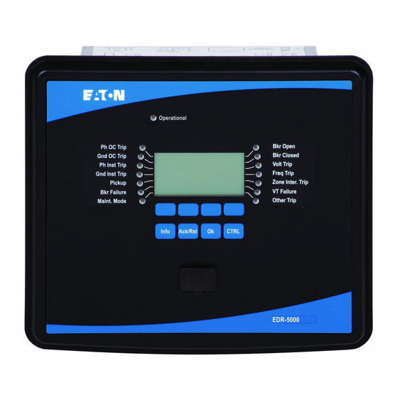
1. The Main Screen shows the relay model –
i.e. EDR‐5000. If the Main Screen is not
shown, press the top left soft‐key (
the Main Screen is displayed.
2. The top 4 soft‐keys (
following descriptions on the Main Screen:
Meas = Measured Values
Rec = Recorders (for EDR, ETR, EGR)
EmgOvr = Emergency Override (for EMR)
Maint = Manual Maintenance Mode
Menu = Complete Menu Tree
FAULT
CONDITION
AND
1. Immediately after the pickup and timeout of
an enabled protection element the display
will show the cause of trip and details from
the fault recorder. After reviewing the
details, press the OK soft‐key.
2. Press the Info soft‐key (
LED info (soft‐key actions begin to blink as
shown on left). A list of the first parameter
assigned to each LED is displayed. Pressing
the Info soft‐key again displays the other
LED set (i.e. right or left side). Press the
right arrow soft‐key (
individual assignments for each LED. A black
arrow points to the displayed LED (i.e. Ph OC
Trip). The dotted box(es) with a check mark
(
) indicates the parameter which has
illuminated the LED. This information can be
verified later using the Event / Waveform
Recorders. Press the up or down arrow soft‐
key (
both the left and right set of LED's.
E‐Series Relays
EDR / EMR / ETR / EGR
MAIN SCREEN
) will have the
LED
OF THE
S
) to display the
) to drill into the
) to scroll thru and review
Page 1 of 4
) until
Advertisement
Table of Contents

Related Manuals for Eaton E Series


Summary of Contents for Eaton E Series
- Page 1 LED set (i.e. right or left side). Press the right arrow soft‐key ( ) to drill into the individual assignments for each LED. A black arrow points to the displayed LED (i.e. Ph OC Trip). The dotted box(es) with a check mark ( ) indicates the parameter which has illuminated the LED. This information can be verified later using the Event / Waveform Recorders. Press the up or down arrow soft‐ key ( ) to scroll thru and review both the left and right set of LED’s. Circuit Protection Division – Electronics (Meters & Relays Business Unit), 7/1/2015, version 2 Page 1 of 4 For technical support call 800‐809‐2772, Options 4, 1. For available documentation and software visit www.eaton.com/pr. ...
- Page 2 If necessary, review and clear the fault conditions displayed via the LED’s from the process on page 1. (i.e. Loss of Utility voltage may cause an undervoltage [27] trip. Utility voltage must return to normal before the condition can be acknowledged / reset.) Circuit Protection Division – Electronics (Meters & Relays Business Unit), 7/1/2015, version 2 Page 2 of 4 For technical support call 800‐809‐2772, Options 4, 1. For available documentation and software visit www.eaton.com/pr. ...
- Page 3 5. To view other measured values, press the left arrow soft‐key ( ) to return to the Measured Values menu, and repeat items 2, 3, and 4 above. Available Measured Values differ for each relay model (EDR‐5000 shown below) Circuit Protection Division – Electronics (Meters & Relays Business Unit), 7/1/2015, version 2 Page 3 of 4 For technical support call 800‐809‐2772, Options 4, 1. For available documentation and software visit www.eaton.com/pr. ...
- Page 4 E‐S CHEAT SHEET ERIES FOR E‐Series Relays EDR / EMR / ETR / EGR IELD PERATIONS ERSONNEL NAVIGATE FACEPLATE MENU OW O THE ‐ The Menu layout from the faceplate is identical to the PowerPort‐E setting software layout. ‐ Available Menu Items differ for each relay model (EDR‐5000 shown below) ‐ PowerPort‐E software is available for download at www.eaton.com/pr. PowerPort‐E software on a Computer Faceplate Menu Layout (Example) (pressed twice) Circuit Protection Division – Electronics (Meters & Relays Business Unit), 7/1/2015, version 2 Page 4 of 4 For technical support call 800‐809‐2772, Options 4, 1. For available documentation and software visit www.eaton.com/pr. ...
Need help?
Do you have a question about the E Series and is the answer not in the manual?
Questions and answers