Sign In
Upload
Manuals
Brands
Eaton Manuals
Relays
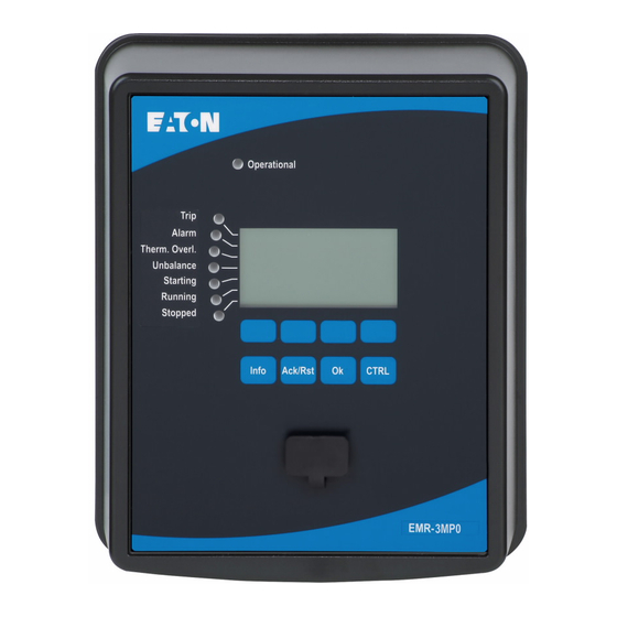
EMR-3MP0
Eaton EMR-3MP0 Manuals
Manuals and User Guides for Eaton EMR-3MP0. We have
1
Eaton EMR-3MP0 manual available for free PDF download: Installation, Operation And Maintenance Manual
Eaton EMR-3MP0 Installation, Operation And Maintenance Manual (281 pages)
Motor Relay
Brand:
Eaton
| Category:
Relays
| Size: 8 MB
Table of Contents
Table of Contents
3
EMR-3MP0 Motor Protection Relay
8
Comments on the Manual
9
Important Definitions
11
Symbols and Definitions
16
Symbols in Function Diagrams
17
Information about the Device
20
Catalog Codes for the EMR-3MP0
22
Front Panel
24
Front Panel Parts
25
Softkey Symbols
27
Modules, Settings, Signals and Values
28
Parameter Settings
31
Menu Structure
36
Device Parameters
38
System Settings
39
Device Planning
40
Security
41
Access Authorizations (Access Areas)
41
Password Handling
41
Passwords - Areas
43
Network Access
47
Reset to Factory Defaults, Reset All Passwords
48
Resets
50
Measuring Values
53
Measurement
54
Powerport-E
56
Qualitymanager
57
Hardware
58
Dimension Drawings
58
EMR-3MP0 - Installation and Wiring
61
Grounding
61
Control Wiring Diagram
62
Overview of Slots - Assembly Groups
65
Communication Protocol Codes
66
Legend for Wiring Diagrams
69
Slot X1
71
DI-4 X1 - Power Supply and Digital Inputs
72
Slot X2
76
OR3-Ano-Ir - Assembly Group with 3 Relay Outputs, Supervision Contact
77
Analog Output, IRIG-B
77
Slot X3
79
Phase and Ground Current Measuring Input Cards
80
Common CT Wiring Configurations
86
Slot X100: Ethernet Interface
89
Ethernet - RJ45
90
Slot X101
91
2.2.10.1 Interface for the URTD Module
92
Slot X103: Data Communication
93
2.2.11.1 RS485 - Modbus® RTU
94
2.2.11.2 Profibus DP/ Modbus® RTU Via Fiber Optic
98
2.2.11.3 Profibus DP Via D-SUB
99
2.2.11.4 Modbus® RTU Via D-SUB
100
2.2.11.5 Ethernet / TCP/IP Via Fiber Optics
101
Slot X120 - PC Interface
102
Input, Output and LED Settings
103
Leds
103
Digital Input Configuration
106
Relay Output Configuration
108
Configuration of the Analog Outputs
109
Communication Protocols
110
General SCADA (Communication) Setting
110
TCP/IP Settings
111
Modbus
113
Profibus
116
DNP Device Planning
122
Dnp3
122
Application Example: Setting a Relay
125
Time Synchronization
126
Sntp
129
Irig-B00X
132
Protective Elements
134
Protection (Prot) Module
134
Blockings
136
Motor Starting and Control Module
137
Motor Start Blocked
139
Reversing or Non-Reversing Starter
140
Motor Start / Transition Trips
141
Start Control
143
Delayed Protection Enabling During Motor Starts
145
Start Limits
147
Anti-Backspin Delay Time (ABS)
148
External Start Blocking
148
Stop Cycle
148
Thermal Block
148
Blocked Condition
148
Forced Starting
149
Trips and Trip Bypass
149
Zero Speed Switch (ZSS on or OFF)
149
Long Acceleration Time (LAT)
151
Incomplete Sequence Report Back Time (INSQ)
152
Emergency Override
153
Thermal Model
154
Locked Rotor Protection
158
Ultimate Trip Current
159
Motor Protection Curves
160
MLS - Load Shedding
163
50J - Jam and Stall Protection
164
Underload Module
166
DEFT Overcurrent Protection
168
Commissioning: Overcurrent Protection, Non-Directional [ANSI 50P]
171
DEFT Measured Ground Fault Protection
173
Functionality
174
Special Notes on Ground (Earth) Fault Current Transformers
175
Commissioning: Ground Fault Protection - Non-Directional [ANSI 50X]
175
Current Unbalance Protection
176
Commissioning: Current Unbalance Module
176
Ex87 - External Differential Protection
179
Commissioning: External Differential Protection
179
Remote Trip
180
Commissioning: Remote Trip
180
26/38/49 - RTD Protection Module
181
URTDII Module Interface
185
Trip Bypass [50BF/62BF]
190
Principle - General Use
190
Trip Bypass Commissioning Example
191
Recorders
193
Trip Bypass Functionality
191
Waveform Recorder
195
Fault Recorder
200
Event Recorder
204
Trend Recorder
205
Motor Start Recorder
206
Statistic Recorder
209
History Function
210
Programmable Logic
212
Self-Supervision
218
Commissioning
223
Commissioning/Protection Test
224
Decommissioning - Removing the Plug from the Relay
225
Forcing the Relay Output Contacts
226
General
226
Service and Commissioning Support
226
Disarming the Relay Output Contacts
228
Forcing Rtds
230
Forcing Analog Outputs
231
Fault Simulator (Sine Wave Generator)
232
Servicing and Maintenance
235
Technical Data EMR-3MP0
237
Specifications of the Real Time Clock
244
Tolerances / Specifications
244
Specifications of the Measured Value Acquisition
245
10.1.3.1 Phase Overcurrent Protection
246
Protection Elements Accuracy
246
10.1.3.2 Ground (Earth) Overcurrent Protection
247
10.1.3.3 Motor Protection
248
10.1.3.4 Thermal Protection
251
10.1.3.5 Current-Related Protection
252
Appendix
253
Approvals
253
Design Standards
253
Standards
253
Electrical Tests
254
Environmental Tests
257
Mechanical Tests
259
Glossary
260
List of ANSI Codes
271
Instantaneous Current Curves (Ground Current Measured)
274
Index
276
Advertisement
Advertisement
Related Products
Eaton EMR-4000
Eaton EMR-5000
Eaton EMR5-AWM580-2
Eaton EMR5-AWM720-2
Eaton EMR5-AWM820-2
Eaton EMR5-A300-1-C
Eaton EMR5-A400-1
Eaton EMR5-W380-1
Eaton EMR5-W400-1
Eaton EMR5-W300-1-C
Eaton Categories
UPS
Circuit breakers
Switch
Industrial Equipment
Industrial Electrical
More Eaton Manuals
Login
Sign In
OR
Sign in with Facebook
Sign in with Google
Upload manual
Upload from disk
Upload from URL