
Related Manuals for Emerson Micro Motion SGM Series


Summary of Contents for Emerson Micro Motion SGM Series
- Page 1 Configuration and Use Manual MMI-20020954, Rev AD March 2018 ® Micro Motion Gas Specific Gravity Meters (SGM) Configuration and Use Manual...
- Page 2 Safety messages Safety messages are provided throughout this manual to protect personnel and equipment. Read each safety message carefully before proceeding to the next step. Emerson Flow customer service Email: • Worldwide: flow.support@emerson.com • Asia-Pacific: APflow.support@emerson.com Telephone: North and South America...
-
Page 3: Table Of Contents
Contents Contents Part I Getting Started Chapter 1 Before you begin ......................3 About this manual ........................3 Model codes and device types ......................3 Communications tools and protocols ...................4 Additional documentation and resources ..................4 Chapter 2 Orientation and planning ....................5 Functional view of the SGM ...................... - Page 4 Contents Change the label for the active calibration ................. 47 Select the active calibration ....................... 47 Chapter 6 Configure measurement units using the display ............49 Configure measurement units using the display .................49 Chapter 7 Configure process measurement using ProLink III ............51 Configure specific gravity, molecular weight, or relative density parameters using ProLink III ...........................
- Page 5 Contents Enable or disable the Acknowledge All Alerts display command ..........88 Configure security for the display menus ...................88 Configure alert handling ......................89 9.4.1 Configure Fault Timeout ....................90 9.4.2 Configure Alert Severity ....................90 Configure informational parameters ..................93 Chapter 10 Integrate the meter with the control system ..............
- Page 6 Contents 13.3 Adjust temperature measurement with Temperature Offset or Temperature Slope ....131 13.4 Perform temperature calibration ..................... 133 13.4.1 Perform temperature calibration using the display ............ 133 13.4.2 Perform temperature calibration using ProLink III ............. 134 13.4.3 Perform temperature calibration using the Field Communicator ......136 13.5 Adjust concentration measurement with Trim Offset ..............
- Page 7 Contents Appendix B Using the transmitter display ..................175 Components of the transmitter interface .................175 Use the optical switches ......................175 Access and use the display menu system ................. 176 B.3.1 Enter a floating-point value using the display ............177 Display codes for process variables ..................180 Codes and abbreviations used in display menus ...............
- Page 8 Contents ® Micro Motion Gas Specific Gravity Meters (SGM)
-
Page 9: Getting Started
Getting Started Part I Getting Started Chapters covered in this part: • Before you begin • Orientation and planning • Quick start Configuration and Use Manual... - Page 10 Getting Started ® Micro Motion Gas Specific Gravity Meters (SGM)
-
Page 11: Before You Begin
Before you begin Before you begin Topics covered in this chapter: • About this manual • Model codes and device types • Communications tools and protocols • Additional documentation and resources About this manual Important This manual assumes that the following conditions apply: •... -
Page 12: Communications Tools And Protocols
HART/Bell 202 Complete configuration and Appendix commissioning You may be able to use other communications tools from Emerson Process Management, such as ™ AMS Suite: Intelligent Device Manager, or the Smart Wireless THUM Adapter. Use of AMS or the Smart Wireless THUM Adapter is not discussed in this manual. For more information on the Smart Wireless THUM Adapter, refer to the documentation available at www.emerson.com. -
Page 13: Orientation And Planning
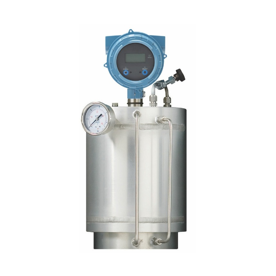
Orientation and planning Orientation and planning Topics covered in this chapter: • Functional view of the SGM • Terms and definitions • Core process variable: Specific gravity, molecular weight, or relative density • Equations used to calculate specific gravity, molecular weight, and relative density Functional view of the SGM SGM components view... - Page 14 Orientation and planning Figure 2-1: Internal and external components Gas calibration valve (valve 1) Gas calibration valve (valve 2) Gas inlet Three-way valve Three-way valve Two-way valve Gauge Regulator Filter Slam shut valve Flowmeter Purge valve Gas output two-way valve Pressure relief one-way valve ®...
-
Page 15: Terms And Definitions
Orientation and planning Terms and definitions Table 2-1: Terms used in meter setup and measurement Term Definition or usage Calibration gas One of the two or three gases used during calibration. Calibration gases are se- lected to match the main constituents of the process gas. Reference gas The gas in the reference chamber. -
Page 16: Core Process Variable: Specific Gravity, Molecular Weight, Or Relative Density
Orientation and planning Table 2-1: Terms used in meter setup and measurement (continued) Term Definition or usage Wobbe index The ratio of the calorific value of a gas to its specific gravity. Measured in volu- metric units (BTU/SCF, and MJ/SCM). Core process variable: Specific gravity, molecular weight, or relative density The SGM can operate as a specific gravity meter, a molecular weight meter, or a relative... -
Page 17: Core Process Variable, Gas Process Variables, And Required Data
Orientation and planning Table 2-2: Core process variable and available process variables (continued) Core process variable Default measure- Available process variables ment unit Specific gravity Molecular weight Relative density ✓ ✓ ✓ Concentration (gas purity) Concentration (% mass) ✓ ✓ ✓... - Page 18 Orientation and planning Table 2-3: Gas measurement when the core process variable is specific gravity (continued) Process data from the Process data from ex- Process variable to be reported meter ternal devices User-specified values Line density Temperature data from External temperature Base pressure meter (RTD) Line pressure...
- Page 19 Orientation and planning Table 2-4: Gas measurement when the core process variable is molecular weight Process data from the Process data from ex- Process variable to be reported meter ternal devices User-specified values Molecular weight Molecular weight Specific gravity Molecular weight Molecular weight of air Base density Molecular weight...
- Page 20 Orientation and planning Table 2-4: Gas measurement when the core process variable is molecular weight (continued) Process data from the Process data from ex- Process variable to be reported meter ternal devices User-specified values Calorific Value Line density % CO Specific gravity % CO2 % H2...
-
Page 21: Equations Used To Calculate Specific Gravity, Molecular Weight, And Relative Density
Orientation and planning Equations used to calculate specific gravity, molecular weight, and relative density Core process variable = Specific gravity The following equations are used when the core process variable is specific gravity. Equation 2-1: Specific gravity SG = K0 + K1 × � + K2 × � Specific gravity of process gas K0, K1, K2 Calibration factors from the on-site calibration. - Page 22 Orientation and planning Equation 2-4: Specific gravity calculated from molecular weight SG = Specific gravity of process gas Molecular weight of process gas (g/mol) Molecular weight of air (user-specified; default = 28.96469 g/mol) Core process variable = Relative density The following equation is used when the core process variable is relative density. Equation 2-5: Relative density RD = K0 + K1 ×...
-
Page 23: Chapter 3 Quick Start
Quick start Quick start Topics covered in this chapter: • Power up the transmitter • Check meter status • Make a startup connection to the transmitter Power up the transmitter The transmitter must be powered up for all configuration and commissioning tasks, or for process measurement. -
Page 24: Make A Startup Connection To The Transmitter
Quick start Table 3-1: Transmitter status reported by status LED LED state Description Recommendation Green No alerts are active. Continue with configuration or process meas- urement. Yellow One or more low-severity alerts are active. A low-severity alert condition does not affect measurement accuracy or output behavior. - Page 25 Quick start • To change the communications parameters using the Field Communicator, choose Configure > Manual Setup > HART > Communications. Important If you are changing communications parameters for the connection type that you are using, you will lose the connection when you write the parameters to the transmitter. Reconnect using the new parameters.
- Page 26 Quick start ® Micro Motion Gas Specific Gravity Meters (SGM)
-
Page 27: Part Ii Configuration And Commissioning
Configuration and commissioning Part II Configuration and commissioning Chapters covered in this part: • Introduction to configuration and commissioning • Purging and calibration • Configure measurement units using the display • Configure process measurement using ProLink III Configure process measurement using the Field Communicator •... - Page 28 Configuration and commissioning ® Micro Motion Gas Specific Gravity Meters (SGM)
-
Page 29: Chapter 4 Introduction To Configuration And Commissioning
Introduction to configuration and commissioning Introduction to configuration and commissioning Topics covered in this chapter: • Default values • Enable access to the off-line menu of the display • Disable HART security • Set the HART lock • Restore the factory configuration Default values Default values for your meter are configured at the factory. - Page 30 Introduction to configuration and commissioning Table 4-1: SGM default mA scaling values (continued) Variable Default 4 mA Default 20 mA Specific gravity for calibration range 3 Specific gravity for calibration range 4 Molecular weight for calibra- 0 g/mol 28.96469 g/mol tion range 1 Molecular weight for calibra- 0 g/mol...
-
Page 31: Enable Access To The Off-Line Menu Of The Display
Introduction to configuration and commissioning Table 4-2: SGM default variables Default variable Output option A Output options B and C Primary Variable (PV), mA1 Sample Temperature • Specific Gravity for Calibration Set 1 • Molecular Weight for Calibration Set • Relative Density Secondary Variable (SV), Time Period B... - Page 32 Introduction to configuration and commissioning Procedure Power down the meter. Using the strap wrench, loosen the grub screws and remove the transmitter end- cap. Figure 4-1: Transmitter with end-cap removed A. Transmitter end-cap Using the hex key, remove the safety spacer. ®...
- Page 33 Introduction to configuration and commissioning Figure 4-2: Transmitter with end-cap and safety spacer removed A. Transmitter end-cap B. Safety spacer Move the HART security switch to the OFF position (up). The HART security switch is the switch on the left. Configuration and Use Manual...
-
Page 34: Set The Hart Lock
Introduction to configuration and commissioning Figure 4-3: HART security switch A. HART security switch B. Unused Replace the safety spacer and end-cap. Power up the meter. Set the HART lock If you plan to use a HART connection to configure the device, you can lock out all other HART masters. -
Page 35: Restore The Factory Configuration
Introduction to configuration and commissioning Option Description Temporary Only the current HART master can make changes to the device. The device will remain locked until manually unlocked by a HART master, or a power-cycle or device reset is performed. The HART master can also change Lock Option to Per- manent. - Page 36 Introduction to configuration and commissioning ® Micro Motion Gas Specific Gravity Meters (SGM)
-
Page 37: Purging And Calibration
Purging and calibration Purging and calibration Topics covered in this chapter: • On-site setup requirements • Preparing for SGM purging and calibration • Purge and purge-cycle the SGM device • Calibrate the SGM device • Review data for all calibrations •... -
Page 38: Core Process Variable: Specific Gravity, Molecular Weight, Or Relative Density
Purging and calibration 5.2.1 Core process variable: Specific gravity, molecular weight, or relative density The SGM can operate as a specific gravity meter, a molecular weight meter, or a relative density meter. This represents the core process variable that gas process data is based on. Your choice determines the set of process variables that the meter can report, the methods used to measure and calculate them, and the data that you must supply during setup and configuration. -
Page 39: Pressure
Purging and calibration • If the SGM is operating as a molecular weight meter, you must enter the molecular weight of the gas. During the calibration, you must be able to flow each calibration gas through the meter, in the order of their specific gravity: lowest to highest. 5.2.4 Pressure You must be able to control the sample pressure and the vent pressure. - Page 40 Purging and calibration General guidelines for selecting a control pressure To select a control pressure using general guidelines: • To minimize the effect of temperature on the meter, use a higher control pressure. • To minimize the effect of temperature on compressibility, use a lower control pressure.
- Page 41 Purging and calibration Table 5-1: Calculation aid for control pressure and associated measurement error (continued) Reference chamber or relief 0.007 0.007 0.007 0.007 valve Total error (%) Equation 5-1: Density range (minimum and maximum) � = P × � × SG �...
- Page 42 Purging and calibration Example: Calculating the control pressure for natural gas Table 5-2: Control pressure and measurement error calculations for natural gas Natural gas Specific gravity range 0.55 to 0.8 DTC (kg/m³/°C) −0.0003 Control pressure at 20 °C lb/in² absolute Bar absolute Density range at 20 °C kg/m³...
-
Page 43: Multiple Calibrations
Purging and calibration 5.2.5 Multiple calibrations The SGM can store calibrations for up to four different process gases or ranges. Each calibration is generated by an independent calibration procedure and contains an independent set of calibration coefficients. This feature allows you to switch between process gases or ranges without recalibrating the device. -
Page 44: Calibrate The Sgm Device
Purging and calibration Procedure Close the isolation valve, the input valve, the calibration valve, and the purge valve (Valve D, Valve A, Valve B, and Valve F. Open the exit valve (Valve C). Open the chamber filling valve (Valve E). Set the pressure regulator to the working pressure of the system. -
Page 45: Calibrate The Sgm Device Using The Display
Purging and calibration • Calibrate the SGM device using the Field Communicator (Section 5.4.3) 5.4.1 Calibrate the SGM device using the display SGM calibration is required to generate calibration coefficients for your process gas. These coefficients are required for accurate measurement. Prerequisites •... - Page 46 Purging and calibration Option Description 2-Point Calibration (2 PT) Appropriate for gases with two main constituents. Requires two cal- ibration gases. 3-Point Calibration (3 PT) Appropriate for gases with three main constituents. Requires three calibration gases. Select the number of the calibration that you want to perform. a.
- Page 47 Purging and calibration e. Enter the specific gravity, molecular weight, or relative density of the calibration gas and store the value. f. Activate SCROLL g. When CAL GAS MEDIUM appears, activate Select to start the calibration. h. During the calibration, activate SCROLL to observe the Sensor Time Period and Stability values during the calibration.
-
Page 48: Calibrate The Sgm Device Using Prolink Iii
Purging and calibration b. Activate SCROLL to view the calibration factors and data. Results are displayed in this order: • The specific gravity, molecular weight, or relative density used to calculate the K0 calibration factor • The time period used to calculate the K0 calibration factor •... - Page 49 Purging and calibration • You must be prepared to flow all calibration gases through the device, at the appropriate sample pressure. In a typical application, the sample pressure should be approximately 25% greater than the control pressure. Procedure Choose Device Tools > Calibration > Gas Calibration. Set the measurement type for this device.
- Page 50 Purging and calibration d. As the gas flows, observe the Sensor Time Period and Stability values. e. Wait a minimum of 15 minutes for the system to stabilize. When Stability is Good, click Accept or Next. If measurement does not stabilize after 30 minutes, click Abort and troubleshoot the problem.
-
Page 51: Calibrate The Sgm Device Using The Field Communicator
Purging and calibration You can also set Active Calibration from the Calibration Data window. This allows you to change the calibration without going through the calibration wizard. For 2-point calibrations, two calibration coefficients (K0 and K2) are calculated and used in measurement. - Page 52 Purging and calibration Option Description Molecular Weight (MW) Gas density will be measured as molecular weight, and molecular weight will be used for calibration. Relative Density (RD) Gas density will be measured as relative density, and relative density will be used for calibration. Set the calibration type (calibration format).
- Page 53 Purging and calibration h. Disconnect the calibration gas. (3-point calibrations only) Set the mid-range calibration point. a. Connect Calibration Gas Medium to the pipework. b. Set the pressure regulator on the calibration gas to the appropriate sample pressure for your installation. c.
-
Page 54: Troubleshooting Sgm Calibration
Purging and calibration For 2-point calibrations, two calibration coefficients (K0 and K2) are calculated and used in measurement. For 3-point calibrations, three calibration coefficients (K0, K1, and K2) are calculated and used in measurement. Postrequisites To restore normal gas flow, close the calibration valve (Valve B) and open the isolation valve (Valve D) and the input valve (Valve A). -
Page 55: Change The Label For The Active Calibration
Purging and calibration Change the label for the active calibration ProLink III Device Tools > Calibration Data Field Communicator Configure > Manual Setup > Calibration Factors Overview You can change the default calibration labels. Procedure Select and delete the value in the Calibration x Label field. Enter your preferred calibration label and press Apply. - Page 56 Purging and calibration ® Micro Motion Gas Specific Gravity Meters (SGM)
-
Page 57: Chapter 6 Configure Measurement Units Using The Display
Configure measurement units using the display Configure measurement units using the display Restriction The display allows you to configure measurement units, but does not support any other process measurement configuration. To access all process measurement parameters, you must use one of the following: •... - Page 58 Configure measurement units using the display ® Micro Motion Gas Specific Gravity Meters (SGM)
-
Page 59: Chapter 7 Configure Process Measurement Using Prolink Iii
Configure process measurement using ProLink III Configure process measurement using ProLink III Topics covered in this chapter: • Configure specific gravity, molecular weight, or relative density parameters using ProLink III • Configure temperature measurement using ProLink III • Configure the pressure input •... -
Page 60: Configure The Molecular Weight Of Air Using Prolink Iii
Configure process measurement using ProLink III Damping affects all process variables that are calculated from the core process variable: specific gravity, molecular weight, or relative density. Procedure Set Damping to the value you want to use. The default value is 0 seconds. The range is 0 to 440 seconds. Interaction between Damping and Added Damping When the mA output is configured to report the core process variable (specific gravity, molecular weight, or relative density), both Damping and Added Damping are applied to... -
Page 61: Configure Temperature Measurement Using Prolink Iii
Configure process measurement using ProLink III Configure temperature measurement using ProLink III The temperature measurement parameters control how temperature is measured and reported. • Configure Temperature Measurement Unit using ProLink III (Section 7.2.1) • Configure Temperature Damping using ProLink III (Section 7.2.2) •... -
Page 62: Configure Temperature Damping Using Prolink Iii
Configure process measurement using ProLink III 7.2.2 Configure Temperature Damping using ProLink III ProLink III Device Tools > Configuration > Process Measurement > Line Temperature > Tempera- ture Damping Overview Temperature Damping controls the amount of damping that will be applied to the line temperature value, when the on-board temperature data is used (RTD). - Page 63 Configure process measurement using ProLink III Procedure Choose the method to be used to supply temperature data, and perform the required setup. Option Description Setup Internal RTD tem- Temperature data from the on- a. Set Line Temperature Source to Internal RTD. perature data board temperature sensor b.
-
Page 64: Configure The Pressure Input
Configure process measurement using ProLink III Verify the wiring between the meter and the external device. Verify the HART tag of the external device. • For digital communications: Verify that the host has access to the required data. Verify that the host is writing to the correct register in memory, using the correct data type. - Page 65 Configure process measurement using ProLink III The meter requires absolute pressure. If you select Gauge, the device will convert the input pressure value to the equivalent absolute pressure. Set Pressure Unit to the unit used by the external pressure device. Choose the method used to supply pressure data and perform the required setup.
-
Page 66: Configure Gas Compressibility Measurement Using Prolink Iii
Configure process measurement using ProLink III Configure gas compressibility measurement using ProLink III ProLink III Device Tools > Configuration > Process Measurement > Compressibility Overview Gas compressibility measurement is required for the following process variables: line density, calorific value, Wobbe index, and energy flow. Gas compressibility measurement can also be used to calculate compressibility as an independent process variable. - Page 67 Configure process measurement using ProLink III The default value is 0. The range is 0.7 to 1.1. b. Set Base Compressibility to the compressibility of your sample gas at base temperature and base pressure. The default value is 1.0. The range is 0.7 to 1.1. c.
-
Page 68: Compressibility Method And Process Limits
Configure process measurement using ProLink III Option Description Setup Polling The meter polls an external de- a. Set % N2 Source to Poll for External Value. vice for % N2 data. b. Set Polling Slot to an available slot. c. Set Polling Control to Poll as Primary or Poll as Secondary. d. -
Page 69: Configure Base Density Calculations Using Prolink Iii
Configure process measurement using ProLink III Table 8-2: Specific gravity and molecular weight meters: Compressibility Method and valid ranges for process variables (continued) Valid range Compressibility Specific Method Temperature Pressure gravity % CO2 % N2 % H2 AGA NX-19 Mod −40 to 0 to 137.9 0.554 to 0.75... -
Page 70: Options For Density Measurement Unit
Configure process measurement using ProLink III This value is also used in line density measurement. Be sure that the value is appropriate for both process variables. Set Base Temperature to the temperature value to which density measurements will be corrected (the reference temperature). The default is 20 °C. -
Page 71: Configure Line Density Calculations Using Prolink Iii
Configure process measurement using ProLink III Overview A special measurement unit is a user-defined unit of measure that allows you to report process data in a unit that is not available in the transmitter. A special measurement unit is calculated from an existing measurement unit using a conversion factor. Procedure Specify Density Special Unit Base. -
Page 72: Configure Energy Content Measurement Using Prolink Iii
Configure process measurement using ProLink III Procedure Choose Device Tools > Configuration > Process Measurement > Line Density. Set Density Unit to the unit to be used for line density, and click Apply. This unit is also used for base density. Verify the value of Line Pressure. - Page 73 Configure process measurement using ProLink III • Hydrogen (H2) Gas composition must be measured in % by volume. If you plan to measure energy flow, you must be able to supply flow data to the meter. You have the following options: •...
- Page 74 Configure process measurement using ProLink III Option Description Setup Polling The meter polls an external de- a. Set % CO2 Source to Poll for External Value. vice for % CO2 data. b. Set Polling Slot to an available slot. c. Set Polling Control to Poll as Primary or Poll as Secondary. d.
- Page 75 Configure process measurement using ProLink III Option Description Setup Fixed value The configured fixed value is a. Set % H2 Source to Fixed Value or Digital Communications. used. b. Set % H2 (Fixed) to the desired value, in % by volume. (Optional) To configure Volume Flow (External) and Mass Flow (Calculated): a.
-
Page 76: Set Up Concentration Measurement Using Prolink Iii
Configure process measurement using ProLink III Option Description Setup Digital communica- A host writes mass flow data to a. Set Mass Flow Source to Fixed Value or Digital Communications. tions the meter at appropriate inter- b. Perform the necessary host programming and communica- vals, and the meter calculates tions setup to write mass flow data to the meter at appropri- the equivalent volume flow. -
Page 77: Select The Active Concentration Matrix Using Prolink Iii
Configure process measurement using ProLink III Procedure Choose Device Tools > Configuration > Process Measurement > Concentration Measurement. To use a gas variable, set Gas Purity Variable to Specific Gravity, Molecular Weight, or Relative Density. Meter Available option Specific gravity Specific Gravity or Molecular Weight Molecular weight Specific Gravity or Molecular Weight... - Page 78 Configure process measurement using ProLink III ® Micro Motion Gas Specific Gravity Meters (SGM)
-
Page 79: Configure Process Measurement Using The Field Communicator
Configure process measurement using the Field Communicator Configure process measurement using the Field Communicator Topics covered in this chapter: • Configure density measurement using the Field Communicator • Configure temperature measurement using the Field Communicator • Configure gas measurement using the Field Communicator •... - Page 80 Configure process measurement using the Field Communicator Table 8-1: Options for Density Measurement Unit Label Unit description Display (standard) ProLink III Field Communicator Grams per cubic centimeter G/CM3 g/cm3 g/Cucm Grams per liter Grams per milliliter G/mL g/ml g/mL Kilograms per liter KG/L kg/l kg/L...
-
Page 81: Configure Density Damping Using The Field Communicator
Configure process measurement using the Field Communicator Example: Defining a special measurement unit for density You want to measure density in ounces per cubic inch. Set Density Special Unit Base to g/cm3. Calculate Density Special Unit Conversion Factor: a. 1 g/cm3 = 0.578 oz/in3 b. -
Page 82: Configure Temperature Measurement Using The Field Communicator
Configure process measurement using the Field Communicator If mA Output Process Variable is set to Specific Gravity, Molecular Weight, or Relative Density, and both Damping and Added Damping are set to non-zero values, density damping is applied first, and the added damping calculation is applied to the result of the first calculation. This value is reported over the mA output. -
Page 83: Configure Temperature Damping Using The Field Communicator
Configure process measurement using the Field Communicator Table 8-2: Options for Temperature Measurement Unit Label Field Communica- Unit description Display ProLink III °C °C degC Degrees Celsius °F °F degF Degrees Fahrenheit °R °R degR Degrees Rankine °K °K Kelvin Kelvin 8.2.2 Configure Temperature Damping using the... -
Page 84: Configure Gas Measurement Using The Field Communicator
Configure process measurement using the Field Communicator The value you enter is automatically rounded to the nearest valid value. Valid values for Temperature Damping are 0, 0.6, 1.2, 2.4, 4.8, … 38.4. Configure gas measurement using the Field Communicator This section guides you through the tasks required to set up and configure gas measurement. - Page 85 Configure process measurement using the Field Communicator Set Base Density to the density of your process gas at reference temperature and reference pressure. Set Base Temperature to the temperature value to which gas measurements will be corrected (the reference temperature). Set Molecular Weight of Air to the value to be used in your application.
-
Page 86: Configure Gas Compressibility Measurement Using The Field Communicator
Configure process measurement using the Field Communicator h. (Optional) Choose Configure > Manual Setup > Measurements > Optional Setup > Gas Measurement > Pressure. i. Set Pressure Offset to the value required to adjust the pressure data for this meter. A fixed pressure value is not recommended. - Page 87 Configure process measurement using the Field Communicator a. Write the line compressibility value to Registers 4183-4184, in 32-bit IEEE floating-point format. The default value is 0. The range is unrestricted. b. Write the base compressibility value to Registers 4141-4142, in 32-bit IEEE floating-point format.
-
Page 88: Configure Energy Content Measurement Using The Field Communicator
Configure process measurement using the Field Communicator Table 8-3: Specific gravity and molecular weight meters: Compressibility Method and valid ranges for process variables Valid range Compressibility Specific Method Temperature Pressure gravity % CO2 % N2 % H2 AGA NX-19 −40 to 1.01325 to 0.55 to 1 0–15%... - Page 89 Configure process measurement using the Field Communicator In either case, you can measure energy flow in either mass units or volume units. The meter automatically selects the appropriate process variable. If you plan to poll an external device for any of these, ensure that the meter has the required polling slots available.
-
Page 90: Set Up Concentration Measurement Using The Field Communicator
Configure process measurement using the Field Communicator k. Set Mass Flow Rate Unit to the unit to be used for Mass Flow (Calculated). (Optional) To configure Mass Flow (External) and Volume Flow (Calculated): a. Choose Configure > Manual Setup > Inputs/Outputs > External Device Polling. b. -
Page 91: Configure A Concentration Measurement Matrix Using The Field Communicator
Configure process measurement using the Field Communicator Next: Configure a concentration measurement matrix using the Field Communicator 8.4.2 Configure a concentration measurement matrix using the Field Communicator A concentration measurement matrix defines the relationship between density and concentration for your process gas. You can configure up to six matrices. Previous: Enable the concentration measurement application using the Field Communicator Prerequisites... - Page 92 Configure process measurement using the Field Communicator ® Micro Motion Gas Specific Gravity Meters (SGM)
-
Page 93: Configure Device Options And Preferences
Configure device options and preferences Configure device options and preferences Topics covered in this chapter: • Configure the transmitter display • Enable or disable the Acknowledge All Alerts display command • Configure security for the display menus • Configure alert handling •... -
Page 94: Configure The Number Of Decimal Places (Precision) Shown On The Display
Configure device options and preferences Overview You can control the process variables and diagnostic variables shown on the display, and the order in which they appear. The display can scroll through up to 15 variables in any order you choose. In addition, you can repeat variables or leave slots unassigned. Restriction You cannot set Display Variable 1 to None or to a diagnostic variable. -
Page 95: Configure The Refresh Rate Of Data Shown On The Display
Configure device options and preferences 9.1.4 Configure the refresh rate of data shown on the display ProLink III Device Tools > Configuration > Transmitter Display > Display Variables Field Communicator Configure > Manual Setup > Display > Display Behavior > Refresh Rate Overview You can set Refresh Rate to control how frequently data is refreshed on the display. -
Page 96: Enable Or Disable The Acknowledge All Alerts Display Command
Configure device options and preferences Scroll Rate may not be available until you apply Auto Scroll. Enable or disable the Acknowledge All Alerts display command ProLink III Device Tools > Configuration > Transmitter Display > Ack All Field Communicator Configure > Manual Setup > Display > Display Menus > Acknowledge All Overview You can configure whether or not the operator can use a single command to acknowledge all alerts from the display. -
Page 97: Configure Alert Handling
Configure device options and preferences Option Description Enabled Default.Operator can access the maintenance section of the off-line menu. This access is required for configuration and calibration, including Known Density Veri- fication. Disabled Operator cannot access the maintenance section of the off-line menu. To control operator access to the alert menu, enable or disable Alert Menu. -
Page 98: Configure Fault Timeout
Configure device options and preferences 9.4.1 Configure Fault Timeout ProLink III Device Tools > Configuration > Fault Processing Field Communicator Configure > Alert Setup > Alert Severity > Fault Timeout Overview Fault Timeout controls the delay before fault actions are performed. Restriction Fault Timeout is applied only to the following alerts (listed by Status Alert Code): A003, A004, A008, A016, A033. - Page 99 Configure device options and preferences Micro Motion recommends using the default settings for Alert Severity unless you have a specific requirement to change them. Procedure Select a status alert. For the selected status alert, set Alert Severity as desired. Option Description Fault Actions when fault is detected:...
- Page 100 Configure device options and preferences Table 9-1: Status alerts and Status Alert Severity (continued) User can reset Alert number Alert title Default severity severity A014 Transmitter Failure Fault A016 Sensor Temperature (RTD) Failure Fault A020 Calibration Factors Missing Fault Fault A021 Transmitter/Sensor/Software Mis- match...
-
Page 101: Configure Informational Parameters
Configure device options and preferences Configure informational parameters ProLink III Device Tools > Configuration > Meter Information Field Communicator Configure > Manual Setup > Info Parameters Overview The informational parameters can be used to identify or describe your meter. They are not used in process measurement and they are not required. - Page 102 Configure device options and preferences ® Micro Motion Gas Specific Gravity Meters (SGM)
-
Page 103: Integrate The Meter With The Control System
Integrate the meter with the control system Integrate the meter with the control system Topics covered in this chapter: • Configure Channel B • Configure the mA output • Configure the discrete output • Configure an enhanced event • Configure HART/Bell 202 communications •... -
Page 104: Configure The Ma Output
Integrate the meter with the control system Option Description mA output Channel B will operate as the secondary mA output. Discrete output Channel B will operate as a discrete output. 10.2 Configure the mA output The mA output is used to report the configured process variable. The mA output parameters control how the process variable is reported. - Page 105 Integrate the meter with the control system Table 10-1: Default settings for mA Output Process Variable Default process variable assign- Device Channel mA output ment SGM mA Channel A Primary mA output Specific gravity, relative density, or molecular weight Channel B Secondary mA output Temperature SGM DO...
- Page 106 Integrate the meter with the control system Table 10-2: Options for mA Output Process Variable (continued) Label Process variable Display ProLink III Field Communicator User-Defined Calculation UCALC User-Defined Calculation User-Defined Calculation Output Output Output Concentration measurement Concentration CONC Concentration Concentration (CM) Net Mass Flow Rate NET M Net Mass Flow Rate...
-
Page 107: Configure Lower Range Value (Lrv) And Upper Range Value (Urv)
Integrate the meter with the control system 10.2.2 Configure Lower Range Value (LRV) and Upper Range Value (URV) ProLink III Device Tools > Configuration > I/O > Outputs > mA Output > mA Output 1 > Lower Range Value Device Tools > Configuration > I/O > Outputs > mA Output > mA Output 1 > Upper Range Vaue Device Tools >... -
Page 108: Configure Added Damping
Integrate the meter with the control system • Set LRV ≥ LSL (lower sensor limit). • Set URV ≤ USL (upper sensor limit). • Set these values so that the difference between URV and LRV is ≥ Min Span (minimum span). Defining URV and LRV within the recommended values for Min Span, LSL, and USL ensures that the resolution of the mA output signal is within the range of the bit precision of the D/A converter. -
Page 109: Configure Ma Output Fault Action And Ma Output Fault Level
Integrate the meter with the control system The default value is 0.0 seconds. The range is 0.0 to 440 seconds. When you specify a value for Added Damping, the transmitter automatically rounds the value down to the nearest valid value. Interaction between mA Output Damping and process variable damping When mA Output Process Variable is set to one of the core process variables (specific... -
Page 110: Configure The Discrete Output
Integrate the meter with the control system The default setting is Downscale. Restriction If Digital Communications Fault Action is set to NAN (not a number), you cannot set mA Output Fault Action to None. If you try to do this, the device will not accept the configuration. If you set mA Output Fault Action to Upscale or Downscale, set mA Output Fault Level as desired. -
Page 111: Configure Discrete Output Source
Integrate the meter with the control system Important Whenever you change a discrete output parameter, verify all other discrete output parameters before returning the meter to service. In some situations, the transmitter automatically loads a set of stored values, and these values may not be appropriate for your application. 10.3.1 Configure Discrete Output Source ProLink III... -
Page 112: Configure Discrete Output Polarity
Integrate the meter with the control system 10.3.2 Configure Discrete Output Polarity ProLink III Device Tools > Configuration > I/O > Outputs > Discrete Output Field Communicator Configure > Manual Setup > Inputs/Outputs > Discrete Output > DO Polarity Overview Discrete outputs have two states: ON (active) and OFF (inactive). -
Page 113: Configure An Enhanced Event
Integrate the meter with the control system Note For some faults only: If Fault Timeout is set to a non-zero value, the transmitter will not implement the fault action until the timeout has elapsed. CAUTION! Do not use Discrete Output Fault Action as a fault indicator. If you do, you may not be able to distinguish a fault condition from a normal operating condition. -
Page 114: Configure Hart/Bell 202 Communications
Integrate the meter with the control system Overview An enhanced event is used to provide notification of process changes. An enhanced event occurs (is ON) if the real-time value of a user-specified process variable moves above (HI) or below (LO) a user-defined setpoint, or in range (IN) or out of range (OUT) with respect to two user-defined setpoints. -
Page 115: Configure Basic Hart Parameters
Integrate the meter with the control system 10.5.1 Configure basic HART parameters ProLink III Device Tools > Configuration > Meter Information Device Tools > Configuration > Communications > Communications (HART) Field Communicator Configure > Manual Setup > HART > Communications Overview Basic HART parameters include the HART address, HART tags, and the operation of the primary mA output. -
Page 116: Configure Hart Variables (Pv, Sv, Tv, Qv)
Integrate the meter with the control system 10.5.2 Configure HART variables (PV, SV, TV, QV) ProLink III Device Tools > Configuration > Communications > Communications (HART) Field Communicator Configure > Manual Setup > Inputs/Outputs > Variable Mapping Overview The HART variables are a set of four variables predefined for HART use. The HART variables include the Primary Variable (PV), Secondary Variable (SV), Tertiary Variable (TV), and Quaternary Variable (QV). - Page 117 Integrate the meter with the control system Table 10-7: Options for HART variables (continued) Primary Varia- Secondary Third Variable Fourth Varia- Process variable ble (PV) Variable (SV) (TV) ble (QV ) ✓ ✓ ✓ ✓ Net Mass Flow Rate ✓ ✓...
-
Page 118: Configure Burst Communications
Integrate the meter with the control system Table 10-8: HART variables and transmitter outputs (continued) HART variable Reported via Comments Quaternary Variable (QV) Not associated with an out- The QV must be configured directly, and the value of the QV is available only via digital communications. 10.5.3 Configure burst communications Burst mode is a mode of communication during which the transmitter regularly broadcasts... - Page 119 Integrate the meter with the control system Table 10-9: Options for burst message contents (continued) Label HART command ProLink III Field Communicator Description Primary Variable (Percent Pct Range/Current The transmitter sends the PV’s actual mA level and Range/Current) the PV’s percent of range in each burst message (e.g.,11.0 mA 25%).
- Page 120 Integrate the meter with the control system Prerequisites Before you can configure trigger mode, the corresponding HART burst message must be enabled. Procedure Select the burst message for which you will set up trigger mode. Set Trigger Mode to the type of trigger you want to use. Option Description Continuous The burst message is sent at Default Update Rate.
- Page 121 Integrate the meter with the control system Overview Event notification uses the burst message mechanism to indicate that an alert has occurred. When event notification is enabled and one or more of the selected alerts occurs, each active burst message will broadcast HART Command 119 until the condition is acknowledged by a HART master.
-
Page 122: Configure Modbus Communications
Integrate the meter with the control system Set Maximum Update Time as desired. Maximum Update Time controls the rate at which HART Command 119 is broadcast when event notification is not active. • Default: 60 seconds 10.6 Configure Modbus communications ProLink III Device Tools >... -
Page 123: Configure Digital Communications Fault Action
Integrate the meter with the control system Code Byte order 3–4 1–2 2–1 4–3 4–3 2–1 See the following table for the bit structure of bytes 1, 2, 3, and 4. Table 10-10: Bit structure of floating-point bytes Byte Bits Definition SEEEEEEE S=Sign... -
Page 124: Options For Digital Communications Fault Action
Integrate the meter with the control system The default setting is None. Restrictions • If mA Output Fault Action is set to None, Digital Communications Fault Action should also be set to None. If you do not, the output will not report actual process data, and this may result in measurement errors or unintended consequences for your process. -
Page 125: Complete The Configuration
Complete the configuration Complete the configuration Topics covered in this chapter: • Test or tune the system using sensor simulation • Back up transmitter configuration • Enable HART security 11.1 Test or tune the system using sensor simulation ProLink III Device Tools >... -
Page 126: Enable Hart Security
Complete the configuration Procedure Choose Device Tools > Configuration Transfer > Save or Load Configuration Data. In the Configuration groupbox, select the configuration data you want to save. Click Save, then specify a file name and location on your computer. Click Start Save. - Page 127 Complete the configuration Figure 11-1: Transmitter with end-cap removed A. Transmitter end-cap Using the hex key, remove the safety spacer. Figure 11-2: Transmitter with end-cap and safety spacer removed A. Transmitter end-cap B. Safety spacer Configuration and Use Manual...
- Page 128 Complete the configuration Move the HART security switch to the ON position (down). The HART security switch is the switch on the left. Figure 11-3: HART security switch A. HART security switch B. Unused Replace the safety spacer and end-cap. Power up the meter.
-
Page 129: Part Iii Operations, Maintenance, And Troubleshooting
Operations, maintenance, and troubleshooting Part III Operations, maintenance, and troubleshooting Chapters covered in this part: • Transmitter operation • Measurement support • Troubleshooting Configuration and Use Manual... - Page 130 Operations, maintenance, and troubleshooting ® Micro Motion Gas Specific Gravity Meters (SGM)
-
Page 131: Chapter 12 Transmitter Operation
Transmitter operation Transmitter operation Topics covered in this chapter: • Record the process variables • View process variables and diagnostic variables • View and acknowledge status alerts 12.1 Record the process variables Micro Motion suggests that you make a record of specific process variable measurements, including the acceptable range of measurements, under normal operating conditions. -
Page 132: View Process Variables Using The Field Communicator
Transmitter operation ProLink III automatically displays process variables, diagnostic variables, and other data on the main screen. ProLink III allows you to choose the process variables that appear on the main screen. You can also choose whether to view data in Analog Gauge view or digital view, and you can customize the gauge settings. -
Page 133: View Alerts Using The Field Communicator
Transmitter operation • The transmitter automatically filters out alerts with Alert Severity set to Ignore. To acknowledge a single alert, check the Ack checkbox for that alert. To acknowledge all alerts at once, click Ack All. Postrequisites • To clear A010, A011, A012, A013 alerts, you must correct the problem, acknowledge the alert, then repeat the calibration. - Page 134 Transmitter operation Table 12-1: Alert data in transmitter memory Transmitter action if condition occurs Alert data structure Contents Clearing Alert List As determined by the alert status bits, a list of: Cleared and regenerated with every transmit- • All currently active alerts ter power cycle •...
-
Page 135: Chapter 13 Measurement Support
Measurement support Measurement support Topics covered in this chapter: • Perform the Known Density Verification procedure • Configure temperature compensation • Adjust temperature measurement with Temperature Offset or Temperature Slope • Perform temperature calibration • Adjust concentration measurement with Trim Offset •... -
Page 136: Perform The Known Density Verification Procedure Using The Field Communicator
Measurement support (Optional) Enter identification data. Click Start, then wait while the meter collects and analyzes process data. This step should be complete in approximately 20 seconds. Check the results in the Results data display. • If all process variables passed the tests, no action is required. Click Close to exit the wizard. -
Page 137: Configure Temperature Compensation
Measurement support 13.2 Configure temperature compensation Temperature compensation adjusts process measurement for the effect of temperature on the sensor. Temperature compensation is always enabled. You must decide how to provide temperature data to the meter, then perform the required configuration and setup. -
Page 138: Configure Temperature Compensation Using The Field Communicator
Measurement support Option Description Setup Polling The meter will poll an external a. Set Temperature Source to Poll for External Value. device for temperature data. b. Set Polling Slot to an available slot. c. Set Polling Control to Poll as Primary or Poll as Secondary. d. -
Page 139: Adjust Temperature Measurement With Temperature Offset Or Temperature Slope
Measurement support Before you decide how to supply temperature data, consider the other ways that line temperature data will be used and plan accordingly. Procedure Choose the method to be used to supply temperature data, and perform the required setup. Method Description Setup... - Page 140 Measurement support Note Temperature offset and temperature slope are applied only to temperature data from the on-board temperature sensors (internal RTD). External temperature data is not adjusted. Although you can set Temperature Offset or Temperature Slope manually, the temperature calibration procedure will generate a pair of offset and slope values that are more accurate for the individual meter.
-
Page 141: Perform Temperature Calibration
Measurement support 13.4 Perform temperature calibration Temperature calibration establishes the relationship between the temperature of the calibration fluids and the signal produced by the sensor. • Perform temperature calibration using the display (Section 13.4.1) • Perform temperature calibration using ProLink III (Section 13.4.2) •... -
Page 142: Perform Temperature Calibration Using Prolink Iii
Measurement support Activate Scroll to view the new offset and slope values. Activate Select to exit. 13.4.2 Perform temperature calibration using ProLink III Temperature calibration establishes the relationship between the temperature of the calibration fluids and the signal produced by the sensor. Prerequisites The temperature calibration is a two-part procedure: temperature offset calibration and temperature slope calibration. - Page 143 Measurement support Procedure Temperature Offset calibration Temperature Slope calibration Fill sensor with low- Fill sensor with high- temperature fluid temperature fluid Wait until sensor achieves Wait until sensor achieves thermal equilibrium thermal equilibrium Service Tools > Service Tools > Maintenance > Maintenance >...
-
Page 144: Perform Temperature Calibration Using The Field Communicator
Measurement support 13.4.3 Perform temperature calibration using the Field Communicator Temperature calibration establishes the relationship between the temperature of the calibration fluids and the signal produced by the sensor. Prerequisites The temperature calibration is a two-part procedure: temperature offset calibration and temperature slope calibration. -
Page 145: Adjust Concentration Measurement With Trim Offset
Measurement support Procedure Temperature Offset calibration Temperature Slope calibration Fill sensor with low- Fill sensor with high- temperature fluid temperature fluid Wait until sensor achieves Wait until sensor achieves thermal equilibrium thermal equilibrium Service Tools > Service Tools > Maintenance > Maintenance >... -
Page 146: Adjust Concentration Measurement With Trim Slope And Trim Offset
Measurement support Procedure Take a concentration reading from the meter, and record line density and line temperature. Subtract the meter value from a reference device. Enter the result as the trim offset. • Using ProLink III: Choose Device Tools > Configuration > Process Measurement > Concentration Measurement, set Matrix Being Configured to your matrix, and enter Trim Offset. - Page 147 Measurement support • For each sample, you must be able to obtain a laboratory concentration value at line density and line temperature. Procedure Collect data for Comparison 1. a. Take a concentration reading from the meter and record line density and line temperature.
-
Page 148: Set Up User-Defined Calculations
Measurement support 50 = � × 49.98 + � Populate the equations: 16 = � × 15.99 + � 50.00 − 16.00 = 34.00 Solve for A: 49.98 − 15.99 = 39.99 34 = � × 33.99 � = 1.00029 50.00 = 1.00029 ×... - Page 149 Measurement support a. Enter the values to be used for the constants: A, B, X, Y. b. Enter the values to be used for a, b, c, d, e, and f. For these terms: • You can specify a constant value. •...
-
Page 150: Equations Used In User-Defined Calculations
Measurement support 13.7.1 Equations used in user-defined calculations Each user-defined calculation has an equation and a set of user-programmable constants and/or user-specified process variables. Equation 13-1: User-defined calculation 1 (square root) �=A + B × � × � + X × � �... - Page 151 Measurement support Table 13-1: Process variables and internal measurement units (continued) Process variable Internal measurement unit Board Temperature °C Drive Gain Concentration % CO, % CO , %N , %H Line Pressure Bar a Sensor Time Period Microseconds Specific Gravity (gas) Unitless Specific Gravity (concentration measurement) Unitless...
- Page 152 Measurement support ® Micro Motion Gas Specific Gravity Meters (SGM)
-
Page 153: Chapter 14 Troubleshooting
Troubleshooting Troubleshooting Topics covered in this chapter: • Quick guide to troubleshooting • Check power supply wiring • Check grounding • Perform loop tests • Status LED states • Status alerts, causes, and recommendations • Density measurement problems • Temperature measurement problems •... -
Page 154: Check Power Supply Wiring
Troubleshooting Verify the power wiring and power supply. Verify the output wiring. The outputs must be powered externally. Verify the grounding. Verify cable shielding. Perform loop tests for each output. Check the sensor installation and orientation. Ensure that it is appropriate for your application. -
Page 155: Check Grounding
Troubleshooting CAUTION! If the transmitter is in a hazardous area, wait five minutes after disconnecting the power. Ensure that the terminals, wires, and wiring compartment are clean and dry. Ensure that the power supply wires are connected to the correct terminals. Ensure that the power supply wires are making good contact, and are not clamped to the wire insulation. -
Page 156: Perform Loop Tests Using The Display
Troubleshooting 14.4.1 Perform loop tests using the display Prerequisites Before performing a loop test, configure the channels for the transmitter inputs and outputs that will be used in your application. Follow appropriate procedures to ensure that loop testing will not interfere with existing measurement and control loops. -
Page 157: Perform Loop Tests Using Prolink Iii
Troubleshooting a. Attach a frequency counter, oscilloscope, digital multimeter (DMM), or digital voltmeter (DVM) to the TPS output loop. b. Compare the reading to the Sensor Time Period process variable at your meter. Postrequisites • If the mA output readings are within 200 microamps of each other, you can correct this discrepancy by trimming the output. -
Page 158: Perform Loop Tests Using The Field Communicator
Troubleshooting Test the discrete outputs. a. Choose Device Tools > Diagnostics > Testing > Discrete Output Test. b. Set Fix To: to ON. c. Verify the signal at the receiving device. d. Set Fix To: to OFF. e. Verify the signal at the receiving device. f. -
Page 159: Status Led States
Troubleshooting d. Select 20 mA. e. Read the mA current at the receiving device and compare it to the transmitter output. The readings do not need to match exactly. If the values are slightly different, you can correct the discrepancy by trimming the output. f. -
Page 160: Status Alerts, Causes, And Recommendations
Troubleshooting • A status LED on the board, beneath the meter housing cover CAUTION! If your meter is in a hazardous area, do not remove the meter housing cover. Use a different method to determine meter status. The status LEDs use colors and flashing to indicate device status. Table 14-1: Transmitter status reported by status LED LED state... - Page 161 Troubleshooting Table 14-2: Status alerts, causes, and recommendations (continued) Alert number Alert title Possible causes Recommended actions A003 No Sensor Re- The transmitter is not re- • Check the drive gain and the pickoff voltage. See sponse ceiving one or more basic Section 14.22 Section 14.23.
- Page 162 Troubleshooting Table 14-2: Status alerts, causes, and recommendations (continued) Alert number Alert title Possible causes Recommended actions A014 Transmitter Many possible causes. • Ensure that all wiring compartment covers are in- Failure stalled correctly. • Ensure that all transmitter wiring meets specifica- tions and that all cable shields are properly termi- nated.
- Page 163 Troubleshooting Table 14-2: Status alerts, causes, and recommendations (continued) Alert number Alert title Possible causes Recommended actions A100 mA Output 1 The calculated mA output • Check the settings of Upper Range Value and Low- Saturated value is outside the config- er Range Value.
- Page 164 Troubleshooting Table 14-2: Status alerts, causes, and recommendations (continued) Alert number Alert title Possible causes Recommended actions A114 mA Output 2 The mA output is config- • Check whether the output is in loop test mode. If Fixed ured to send a constant val- it is, unfix the output.
-
Page 165: Density Measurement Problems
Troubleshooting 14.7 Density measurement problems Table 14-3: Density measurement problems and recommended actions Problem Possible causes Recommended actions Erratic density reading • Normal process noise • Check your process conditions. • Line pressure too low • Increase the density damping value. •... -
Page 166: Temperature Measurement Problems
Troubleshooting 14.8 Temperature measurement problems Table 14-4: Temperature measurement problems and recommended actions Problem Possible causes Recommended actions Temperature reading • RTD failure • Verify that the temperature compensation significantly different • Incorrect compensation factors factors match the value on the sensor tag from process temper- •... -
Page 167: Gas Measurement Problems
Troubleshooting A thermal insulation jacket should protect both the sensor body and the flanges. A thermal insulation jacket designed specifically for your meter is available from Micro Motion. See the product data sheet for your meter. 14.9 Gas measurement problems Table 14-5: Gas measurement problems and recommended actions Problem... -
Page 168: Milliamp Output Problems
Troubleshooting 14.11 Milliamp output problems Table 14-7: Milliamp output problems and recommended actions Problem Possible causes Recommended actions No mA output • Output not powered • Verify that the output loop is powered ex- • Wiring problem ternally. • Circuit failure •... -
Page 169: Discrete Output Problems
Troubleshooting Table 14-7: Milliamp output problems and recommended actions (continued) Problem Possible causes Recommended actions Consistently incorrect • Loop problem • Check the mA output trim. See mA measurement • Output not trimmed correctly Section 14.15. • Incorrect measurement unit configured for •... -
Page 170: Time Period Signal (Tps) Output Problems
Troubleshooting 14.13 Time Period Signal (TPS) output problems Table 14-9: TPS output problems and recommended actions Problem Possible causes Recommended actions No TPS output • The TPS output is not supported on this • Verify that the output loop is powered ex- device ternally. -
Page 171: Trim Ma Outputs Using Prolink Iii
Troubleshooting • Trim mA outputs using ProLink III (Section 14.15.1) • Trim mA outputs using the Field Communicator (Section 14.15.2) 14.15.1 Trim mA outputs using ProLink III Trimming the mA output establishes a common measurement range between the transmitter and the device that receives the mA output. Important You must trim the output at both ends (4 mA and 20 mA) to ensure that it is compensated accurately across the entire output range. -
Page 172: Check Hart Communications
Troubleshooting Important The HART signal over the primary mA output affects the mA reading. Disconnect the wiring between the Field Communicator and the transmitter terminals when reading the primary mA output at the receiving device. Reconnect to continue the trim. Check the trim results. -
Page 173: Check Lower Range Value And Upper Range Value
Troubleshooting Figure 14-1: Wiring and power to test terminals A. Voltmeter B. 250–600 Ω resistance C. External power supply D. Transmitter with end-cap removed c. Using a voltmeter, check the voltage drop across the resistor. For a 250 Ω resistor, 4–20 mA = 1–5 VDC. If the voltage drop is less than 1 VDC, add resistance to achieve a voltage drop within the required range. -
Page 174: Check Ma Output Fault Action
Troubleshooting 14.18 Check mA Output Fault Action mA Output Fault Action controls the behavior of the mA output if the transmitter encounters an internal fault condition. If the mA output is reporting a constant value below 4 mA or above 20 mA, the transmitter may be in a fault condition. Check the status alerts for active fault conditions. -
Page 175: Check The Coalescing Filter
Troubleshooting Procedure Check for a leak from the reference chamber to the atmosphere. This can cause low density readings. a. Observe the reference chamber pressure reading. If this leak is present, the reference chamber pressure will be low. b. Apply a soap solution around the reference chamber valve and the fitting into the reference chamber. -
Page 176: Check The Drive Gain
Troubleshooting CAUTION! Do not operate the SGM with air in the system. Air in the system, combined with corrosion, can create a source of ignition. 14.22 Check the drive gain Use the following table to check drive gain values. If you see a value that is too high or too low, there could be a problem with the process or with the device. -
Page 177: Collect Drive Gain Data
Troubleshooting Table 14-11: Possible causes and recommended actions for excessive (saturated) drive gain (continued) Possible cause Recommended actions Drive board or module failure Contact Micro Motion. Vibrating element not free to Ensure that the vibrating element is free to vibrate. vibrate Open drive coil Contact Micro Motion. -
Page 178: Collect Pickoff Voltage Data
Troubleshooting Table 14-13: Possible causes and recommended actions for low pickoff voltage Possible cause Recommended actions Moisture, settling of two-phase or • Increase the inlet or back pressure at the meter. three-phase fluids • If a pump is located upstream from the meter, increase the distance between the pump and meter. -
Page 179: Locate A Device Using The Hart 7 Squawk Feature
Troubleshooting 14.25 Locate a device using the HART 7 Squawk feature The Squawk feature causes the device to show a specific pattern on its display. You can use this to locate or identify a device. Restriction The Squawk feature is available only with HART 7 connections. It is not available with ProLink III. Procedure Choose Service Tools >... - Page 180 Troubleshooting ® Micro Motion Gas Specific Gravity Meters (SGM)
-
Page 181: Appendix A Calibration Certificate
Calibration certificate Appendix A Calibration certificate Sample calibration certificate Your meter was shipped with a calibration certificate. The calibration certificate describes the calibrations and configurations that were performed or applied at the factory. Configuration and Use Manual... - Page 182 Calibration certificate Figure A-1: Sample calibration certificate CALIBRATION CERTIFICATE SGM GAS SPECIFIC GRAVITY METER SERIAL NO 980731 SGM3AAAAC2Z9EZBZTG CAL DATE 21-May-2013 PRESSURE TEST 20 Bar AMPLIFIER NO 1686 CYLINDER NO 6435 CUSTOMER TAG NO DERF-DOGGER-009361 SPECIFIC GRAVITY CALIBRATION COEFFICIENTS @ 20°C : SG = K0 + K1*TP + K2*TP²...
-
Page 183: Appendix B Using The Transmitter Display
Using the transmitter display Appendix B Using the transmitter display Topics covered in this appendix: • Components of the transmitter interface • Use the optical switches • Access and use the display menu system • Display codes for process variables •... -
Page 184: Access And Use The Display Menu System
Using the transmitter display Access and use the display menu system The display menu system is used to perform various configuration, administrative, and maintenance tasks. The display menu system does not provide complete configuration, administrative, or maintenance functions. For complete transmitter management, you must use another communications tool. Prerequisites To access the display menu system, operator access to either the Off-Line menu or the Alert menu must be enabled. -
Page 185: Enter A Floating-Point Value Using The Display
Using the transmitter display • Activate Scroll until the EXIT option is displayed, then activate Select. • If the EXIT option is not available, activate Scroll and Select simultaneously and hold until the screen returns to the previous display. To exit the display menu system, you can use either of the following methods: •... - Page 186 Using the transmitter display If the current value is positive and there is a blank space at the left of the value, activate Select until the cursor is flashing under the blank space, then activate Scroll until the minus sign appears. If the current value is positive and there is no blank space at the left of the value, activate Select until the cursor is flashing under the leftmost digit, then activate Scroll until the minus sign appears.
- Page 187 Using the transmitter display • S = Sign. A minus sign (−) indicates a negative number. A blank indicates a positive number. • X.XXX = The 4-digit mantissa. • E = The exponent indicator. • YY = The 2-digit exponent. Procedure Switch from decimal notation to exponential notation.
-
Page 188: Display Codes For Process Variables
Using the transmitter display To save the displayed value to transmitter memory, activate Scroll and Select simultaneously and hold until the display changes. • If the displayed value is the same as the value in transmitter memory, you will be returned to the previous screen. -
Page 189: Codes And Abbreviations Used In Display Menus
Using the transmitter display Table B-2: Display codes for process variables (continued) Code Definition Molecular Weight Energy measurement Calorific Value WOBBE Wobbe Index ENRGY/FLOW Energy Flow Codes and abbreviations used in display menus Table B-3: Display codes for measurement units Code Measurement unit Percent... - Page 190 Using the transmitter display Table B-3: Display codes for measurement units (continued) Code Measurement unit BBL/D Barrels per day BBL/H Barrels per hour BBL/MN Barrels per minute BBL/S Barrels per second BTU/D British Thermal Units per day BTU/H British Thermal Units per hour BTU/lb British Thermal Units per pound BTU/MN...
- Page 191 Using the transmitter display Table B-3: Display codes for measurement units (continued) Code Measurement unit G/mL Grams per milliliter G/MOL Grams per mole Grams per second G/SCM Grams per square centimeter Hectoliters HOUR Hours Hectopascals Hertz Inches INH2O Inches of water at 68 °F INHG Inches of mercury at 0 °C INW4C...
- Page 192 Using the transmitter display Table B-3: Display codes for measurement units (continued) Code Measurement unit LT/H Long tons per hour Meters per hour Meters per second Cubic meters M3/D Cubic meters per day M3/H Cubic meters per hour M3/MIN Cubic meters per minute M3/S Cubic meters per second Milliamperes...
- Page 193 Using the transmitter display Table B-3: Display codes for measurement units (continued) Code Measurement unit NM3/S Normal cubic meters per second Ohms OUNCE Ounce Pascals Picofarads Parts per million PRF/M Proof per mass PRF/V Proof per volume Pounds per square foot Pounds per square inch gauge PSI A Pounds per square inch absolute...
- Page 194 Using the transmitter display Table B-3: Display codes for measurement units (continued) Code Measurement unit T/MIN Metric tons per minute TONUK Long tons (2240 pounds) TONUS Short tons (2000 pounds) TORR Torr at 0 °C UKGAL Imperial gallons UKGPD Imperial gallons per day UKGPH imperial gallons per hour UKGPM...
- Page 195 Using the transmitter display Table B-4: Display codes for menus, controls, and data (continued) Code Definition AO 1 mA Output 1 AO 1 SRC mA Output 1 Source AO 2 mA Output 2 AO 2 SRC mA Output 2 Source API (American Petroleum Institute) APPLY Apply...
- Page 196 Using the transmitter display Table B-4: Display codes for menus, controls, and data (continued) Code Definition Maximum deviation DGAIN Drive gain DISBL Disabled DISPLAY Display Discrete Output DO SRC Discrete Output Source DRIVE Drive gain DRIVE% Drive gain DSPLY Display DYNV Dynamic viscosity ENABL...
- Page 197 Using the transmitter display Table B-4: Display codes for menus, controls, and data (continued) Code Definition HART HART HIDE Hide HIGH High Input/Output K VAL K value K0 calibration factor K1 calibration factor K2 calibration factor Known Density Verification KINV Kinematic viscosity LANG Language...
- Page 198 Using the transmitter display Table B-4: Display codes for menus, controls, and data (continued) Code Definition OFFLN Offline OFFSET Offset OFFST Offset O-O-O-O HART Squawk display Out of range PASS Password or passcode PASSW Password or passcode POLAR Polarity POLARITY Polarity POOR Poor...
- Page 199 Using the transmitter display Table B-4: Display codes for menus, controls, and data (continued) Code Definition Specific gravity Specific gravity SHOW Show Simulate, Simulated SLOPE Slope SPAN Spanish Source SRVIS Secondary referred viscosity STAB Stability START Start STORE Store Software SWREV Software revision TCASE...
- Page 200 Using the transmitter display Table B-4: Display codes for menus, controls, and data (continued) Code Definition ZERO Zero ® Micro Motion Gas Specific Gravity Meters (SGM)
-
Page 201: Appendix C Using Prolink Iii With The Transmitter
In most ProLink III installations, the manual is installed with the ProLink III program. Additionally, the ProLink III manual is available on the documentation CD or the web site at www.emerson.com. ProLink III features and functions ProLink III offers complete transmitter configuration and operation functions. ProLink III also offers a number of additional features and functions, including: •... -
Page 202: Connect With Prolink Iii
Using ProLink III with the transmitter • The ability to connect to and view information for more than one device • A guided connection wizard These features are documented in the ProLink III manual. They are not documented in the current manual. -
Page 203: Connect With Prolink Iii Over Modbus/Rs-485
Using ProLink III with the transmitter • You cannot make concurrent Modbus connections if the connections use the same terminals. You can make concurrent Modbus connections if the connections use different terminals. C.2.2 Connect with ProLink III over Modbus/RS-485 You can connect directly to the RS-485 terminals on the transmitter or to any point on the network. - Page 204 Using ProLink III with the transmitter Figure C-1: Connection to RS-485 terminals A. PC B. RS-232 to RS-485 converter C. Transmitter with end-cap removed Note This figure shows a serial port connection. USB connections are also supported. To connect over the RS-485 network: a.
- Page 205 Using ProLink III with the transmitter Figure C-2: Connection over network A. PC B. RS-232 to RS-485 converter Ω , 1/2-watt resistors at both ends of the segment, if necessary C. 120- D. DCS or PLC E. Transmitter with end-cap removed Note This figure shows a serial port connection.
-
Page 206: Connect With Prolink Iii Over Hart/Bell 202
Using ProLink III with the transmitter Table C-1: RS-485 connection parameters (continued) Optional or re- Connection type Parameter Value quired? Auto-detection Address The Modbus address config- Required ured for this transmitter. The default is 1. Baud Rate 1200 to 38400 Optional Yes. - Page 207 Using ProLink III with the transmitter CAUTION! If the transmitter is in a hazardous area, do not remove the transmitter end-cap while the transmitter is powered up. Removing the end cap while the transmitter is powered up could cause an explosion. To connect to the transmitter in a hazardous environment, use a connection method that does not require removing the transmitter end-cap.
- Page 208 Using ProLink III with the transmitter Figure C-3: Connection to mA output terminals A. PC B. RS-232 to Bell 202 converter Ω resistance C. 250–600 D. External power supply E. Transmitter with end-cap removed Note This figure shows a serial port connection. USB connections are also supported. The signal converter must be connected across a resistance of 250–600 Ω.
- Page 209 Using ProLink III with the transmitter Figure C-4: Supply voltage and resistance requirements A. External resistance (ohms) B. Supply voltage VDC (volts) C. Operating range Note To connect to a point in the local HART loop: a. Attach the leads from the signal converter to any point in the loop, ensuring that the leads are across the resistor.
- Page 210 Using ProLink III with the transmitter Figure C-5: Connection over local loop A. PC B. RS-232 to Bell 202 converter C. Any combination of resistors R1 and R2 as necessary to meet HART communication resistance requirements D. DCS or PLC E.
- Page 211 Using ProLink III with the transmitter Figure C-6: Supply voltage and resistance requirements A. External resistance (ohms) B. Supply voltage VDC (volts) C. Operating range Note To connect over a HART multidrop network: a. Attach the leads from the signal converter to any point in the loop. b.
- Page 212 Using ProLink III with the transmitter Figure C-7: Connection over multidrop network A. RS-232 to Bell 202 converter Ω resistance B. 250–600 C. Devices on the network D. Master device Start ProLink III. Choose Connect to Physical Device. Set Protocol to HART Bell 202. HART/Bell 202 connections use standard connection parameters.
- Page 213 Using ProLink III with the transmitter Click Connect. Need help? If an error message appears: • Verify the HART address of the transmitter, or poll HART addresses 1–15. • Ensure that there is at least 1 VDC across the connection terminals. Add resistance as necessary to achieve at least 1 volt.
- Page 214 Using ProLink III with the transmitter ® Micro Motion Gas Specific Gravity Meters (SGM)
-
Page 215: Appendix D Using The Field Communicator With The Transmitter
If you are unable to perform these tasks, consult the Field Communicator manual before attempting to use the Field Communicator. The Field Communicator manual is available on the Micro Motion documentation CD or the Micro Motion web site (www.emerson.com). Device descriptions (DDs) In order for the Field Communicator to work with your device, the appropriate device description (DD) must be installed. -
Page 216: Connect With The Field Communicator
Using the Field Communicator with the transmitter Field Communicator menus and messages Many of the menus in this manual start with the On-Line menu. Ensure that you are able to navigate to the On-Line menu. As you use the Field Communicator with a Micro Motion transmitter, you will see a number of messages and notes. - Page 217 Using the Field Communicator with the transmitter HART connections are not polarity-sensitive. It does not matter which lead you attach to which terminal. Figure D-1: Field Communicator connection to transmitter terminals A. Field Communicator Ω resistance B. 250–600 C. External power supply D.
- Page 218 Using the Field Communicator with the transmitter Figure D-2: Field Communicator connection to local HART loop A. Field Communicator Ω resistance B. 250–600 C. External power supply D. Transmitter with end-cap removed To connect to a point in the HART multidrop network, attach the leads from the Field Communicator to any point on the network.
- Page 219 Using the Field Communicator with the transmitter If you are connecting across a multidrop network: • Set the Field Communicator to poll. The device returns all valid addresses. • Enter the HART address of the transmitter. The default HART address is 0. However, in a multidrop network, the HART address has probably been set to a different, unique value.
- Page 220 Using the Field Communicator with the transmitter ® Micro Motion Gas Specific Gravity Meters (SGM)
- Page 221 Using the Field Communicator with the transmitter Configuration and Use Manual...
- Page 222 © 2018 Micro Motion, Inc. All rights reserved. The Emerson logo is a trademark and service mark of Emerson Electric Co. Micro Motion, ELITE, ProLink, MVD and MVD Direct Connect marks are marks of one of the Emerson Automation Solutions family of companies. All other marks are property of their respective owners.
Need help?
Do you have a question about the Micro Motion SGM Series and is the answer not in the manual?
Questions and answers