Emerson Micro Motion Installation Manual
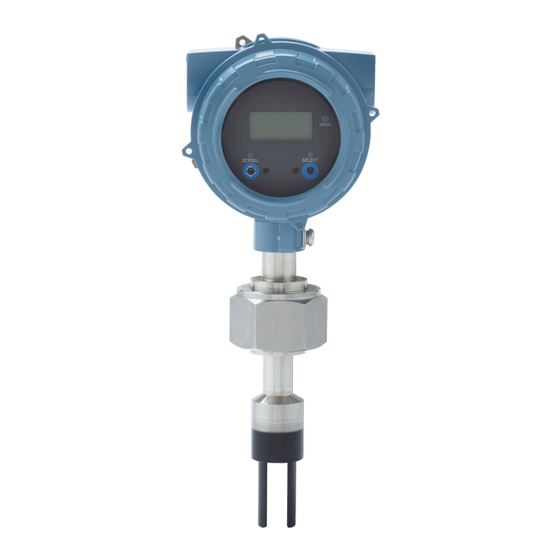
Fork viscosity meter
Hide thumbs
Also See for Micro Motion:
- Configuration and use manual (212 pages) ,
- User manual (76 pages) ,
- Installation manual (74 pages)

Related Manuals for Emerson Micro Motion


Summary of Contents for Emerson Micro Motion
- Page 1 Installation Manual MMI-20020994, Rev AB July 2015 ® Micro Motion Fork Viscosity Meters Direct insertion viscosity meter installation...
- Page 2 Safety and approval information This Micro Motion product complies with all applicable European directives when properly installed in accordance with the instructions in this manual. Refer to the EC declaration of conformity for directives that apply to this product. The EC declaration of...
-
Page 3: Table Of Contents
Contents Contents Chapter 1 Planning ........................... 1 Installation checklist ........................1 Best practices ..........................2 Power requirements ........................2 Other installation considerations ....................4 Recommended installations for short-stem meters .................7 Perform a meter check (pre-installation) ..................9 Chapter 2 Mounting ........................11 Mount in free-stream application (flanged fitting) .................11 Mount in free-stream application (weldolet fitting) ...............12 Mount with a T-piece (flanged fitting) ................... - Page 4 Contents Micro Motion Fork Viscosity Meter...
-
Page 5: Chapter 1 Planning
Model 1700 and Model 2700 Transmitters: Installation Manual. Consider the maximum cable length between the meter and transmitter. The maximum recommended distance between the two devices is 1000 ft (300 m). Micro Motion recommends using Micro Motion cable. Installation Manual... -
Page 6: Best Practices
Minimum recommended voltage: 21.6 VDC with 1000 ft of 24 AWG (300 m of 0.20 mm ) power-supply cable • At startup, power source must provide a minimum of 0.5 A of short-term current at a minimum of 19.6 V at the power input terminals. Micro Motion Fork Viscosity Meter... - Page 7 Planning Power cable recommendations for explosion-proof/flameproof meters Figure 1-1: Minimum wire gauge (AWG per feet) Minimum Wire Gauge 21.6V 1200 1500 1800 2100 2400 2700 3000 Distance of Installation (ft) Figure 1-2: Minimum wire area (mm per meter) Minimum Wire Area (mm 0.400 0.350 0.300...
-
Page 8: Other Installation Considerations
Calibration boundaries Important Micro Motion calibrates all meters at the factory according to the sensor calibration range selected at point of purchase. The factory calibration process takes into account the potential boundary effect of the planned installation. At point of installation, confirm that the meter calibration range and boundary matches the planned installation to ensure optimum performance of the meter. - Page 9 Planning Figure 1-3: Region of measurement boundary or sensitivity Long axis Short axis Sensitive, or effective, region When installing the meter, if part of this effective region or volume is interfered with because of the pipework or fittings a boundary effect exists (see Figure 1-4).
- Page 10 Keep pipe lines full of fluid at all times. • Vent any gas prior to the meter installation location. • Avoid sudden pressure drops or temperature changes which may cause dissolved gases to break out of the fluid. Micro Motion Fork Viscosity Meter...
-
Page 11: Recommended Installations For Short-Stem Meters
Recommended installations for short-stem meters Micro Motion recommends three standard installations for the short-stem meter to alleviate any need for onsite calibration. All meters are factory calibrated for these types of installations and take into consideration the potential boundary effect of each installation. - Page 12 • Suitable for complex referrals and for use with heat exchangers • Suitable for step changes in viscosity • Fast response • Ideal for analyzer cubicles Micro Motion Fork Viscosity Meter...
-
Page 13: Perform A Meter Check (Pre-Installation)
Handle the meter with care. Follow local practices for lifting or moving the meter. Visually inspect the meter for any physical damage. If you notice any physical damage to the meter, immediately contact Micro Motion Customer Support at flow.support@emerson.com. Connect and power up the meter. - Page 14 If the meter passes the test, then it has not drifted or changed since its factory calibration. For more information on performing a KDV check, see the configuration and use manual that shipped with the product. Micro Motion Fork Viscosity Meter...
-
Page 15: Chapter 2 Mounting
Mounting Mounting Topics covered in this chapter: • Mount in free-stream application (flanged fitting) • Mount in free-stream application (weldolet fitting) • Mount with a T-piece (flanged fitting) • Mount with a flow-through chamber • Mount in an open tank (long-stem meter) •... -
Page 16: Mount In Free-Stream Application (Weldolet Fitting)
• Before fitting the weldolet, you must bore a 2.1 in (52.5 mm) diameter opening in the pipeline to accept the meter. You must weld the weldolet to the pipeline concentrically with the pre-bored hole. Micro Motion Fork Viscosity Meter... -
Page 17: Mount With A T-Piece (Flanged Fitting)
Mounting Procedure Figure 2-2 for information on installing the meter (with a weldolet fitting) in a free- stream application. Important You must always install the meter horizontally and oriented to allow flow in the gap between the tines, irrespective of the pipeline orientation (horizontal or vertical). This position helps to prevent the trapping of bubbles or solids on the meter –... - Page 18 Plan view of a vertical pipe installation A. 4-inch pipe or larger for horizontal or vertical installations B. Distance of meter tines from main pipe wall is determined by the maximum flow rate of the process. C. PFA ring and circlip Micro Motion Fork Viscosity Meter...
-
Page 19: Mount With A Flow-Through Chamber
Mounting Mount with a flow-through chamber Flow-through chambers are manufactured by Micro Motion, and are available with either weld-prepared ends or with flange or compression fittings for connection into the process pipelines. They are available with 1- inch NB, 2-inch NB, or 3-inch NB inlet and outlet pipes. -
Page 20: Mount In An Open Tank (Long-Stem Meter)
Only the safe area version of the long-stem meter can be mounted in an open tank. Procedure Clamp the long-stem meter to a structure, positioning the clamp to determine the insertion depth of the meter. Micro Motion Fork Viscosity Meter... - Page 21 Mounting Figure 2-5: Open-tank meter installation (long stem) Confirm the meter tines are away from the tank wall. Figure 2-6: Meter placement (away from tank wall) A. 50 mm B. 200 mm Confirm the meter tines are immersed in fluid. Installation Manual...
- Page 22 Figure 2-8: Meter placement (distance from objects and disturbed flow) A. 200 mm If flow exists, confirm the meter tines are aligned so that the flow is directed towards or through the gap between the tines. Micro Motion Fork Viscosity Meter...
-
Page 23: Mount In A Closed Tank (Long-Stem Meter)
Mounting Figure 2-9: Meter placement (flow direction through tine gap) Confirm the meter tines are kept away from deposit buildup. Figure 2-10: Meter placement (away from deposit buildup) Mount in a closed tank (long-stem meter) Attach the long-stem meter using the fitted flange attachment (shipped with the product). - Page 24 Mounting Figure 2-11: Closed-tank installation (fitted flange attachment) (Optional) To vary the insertion depth of the meter, mount the meter on a standoff section that attaches to the flange (not provided). Micro Motion Fork Viscosity Meter...
- Page 25 Mounting Figure 2-12: Closed-tank installation (with standoff) A. Standoff height can vary (provided by customer) Confirm the meter tines are away from the tank wall. Figure 2-13: Meter placement (away from tank wall) A. 200 mm B. 50 mm Confirm the meter tines are immersed in fluid. Installation Manual...
- Page 26 Figure 2-15: Meter placement (allowance for tank lid flexing) A. 200 mm Confirm the meter tines are placed away from objects and disturbed flow. Micro Motion Fork Viscosity Meter...
- Page 27 Mounting Figure 2-16: Meter placement (distance from objects and disturbed flow) A. 200 mm If flow exists, confirm the meter tines are aligned so that the flow is directed towards or through the gap between the tines. Figure 2-17: Meter placement (flow direction through tine gap) Confirm the meter tines are kept away from deposit buildup.
-
Page 28: Attach The Pfa Ring And Circlip
If you are using the Zirconium version of the meter, a self-locking PFA ring is provided and does not require a circlip to keep it in place. Procedure Figure 2-19 for information on attaching the PFA ring and circlip to the meter. Micro Motion Fork Viscosity Meter... -
Page 29: Rotate The Electronics On The Meter (Optional)
Mounting Figure 2-19: Attaching a PFA ring and circlip A. Circlip (not provided with self-locking PFA rings) B. PFA ring C. PFA ring and circlip attached Rotate the electronics on the meter (optional) You can rotate the transmitter on the meter up to 90°. Using a 4 mm hex key, loosen the cap screw that holds the transmitter in place. -
Page 30: Rotate The Display On The Transmitter (Optional)
If the display pins come out of the board stack with the display module, remove the pins and reinstall them. Rotate the display module to the desired position. Insert the sub-bezel pin terminals into the display module pin holes to secure the display in its new position. Micro Motion Fork Viscosity Meter... - Page 31 Mounting If you have removed the display screws, line them up with the matching holes on the sub-bezel, then reinsert and tighten them. Place the display cover onto the main enclosure. Turn the display cover clockwise until it is snug. Power up the meter.
- Page 32 Mounting Micro Motion Fork Viscosity Meter...
-
Page 33: Chapter 3 Wiring
Wiring Wiring Topics covered in this chapter: • Available output terminals and wiring requirements • Explosion-proof/flameproof or non-hazardous output wiring ™ • Processor wiring for remote-mount 2700 FOUNDATION fieldbus option • Wiring to external devices (HART multidrop) • Wiring to signal converters and/or flow computers Available output terminals and wiring requirements Three pairs of wiring terminals are available for transmitter outputs. -
Page 34: Explosion-Proof/Flameproof Or Non-Hazardous Output Wiring
CAUTION! Meter installation and wiring should be performed by suitably trained personnel only in accordance with the applicable code of practice. Procedure Wire to the appropriate output terminal and pins (see Figure 3-1). Micro Motion Fork Viscosity Meter... - Page 35 Wiring Figure 3-1: Wiring the Analog outputs version mA1+ HART RS-485 A RS-485 RS-485 B A. 24 VDC B. R (250 Ω resistance) load C. HART-compatible host or controller; and/or signal device D. Signal device Note Ω is For operating the milliamp outputs with a 24V supply, a maximum total loop resistance of 657 allowed.
- Page 36 CAUTION! Meter installation and wiring should be performed by suitably trained personnel only in accordance with the applicable code of practice. Procedure Wire to the appropriate output terminal and pins (see Figure 3-2). Micro Motion Fork Viscosity Meter...
- Page 37 Wiring Figure 3-2: Wiring the Discrete output version mA1+ HART RS-485 A RS-485 RS-485 B A. 24 VDC B. R (250 Ω resistance) load C. HART-compatible host or controller; and/or signal device Ω resistance recommended) D. R (500 load E. Discrete input device Note Ω...
-
Page 38: Processor Wiring For Remote-Mount 2700 Foundation Fieldbus Option
Internal resistance (R Cable parameters for Group IIC Maximum external capacitance (C 85 nF Maximum external inductance (L 25 µH Maximum external inductance/resistance ratio 31.1 µH/Ω Cable parameters for Group IIB Maximum external capacitance (C 660 nF Micro Motion Fork Viscosity Meter... - Page 39 Wiring Table 3-2: RS-485 output and cable entity parameters (continued) Maximum external inductance (L 260 µH Maximum external inductance/resistance ratio 124.4 µH/Ω 3.3.2 Prepare the 4-wire cable Important For user-supplied cable glands, the gland must be capable of terminating the drain wires. Note If you are installing unshielded cable in continuous metallic conduit with 360º...
- Page 40 3. Strip all but 1/2 inch (12 mm) of shielding. Wrap the drain wires twice around the shield and cut off the excess drain wires. Drain wires wrapped around shield Go to the shielding procedure Micro Motion Fork Viscosity Meter...
- Page 41 Micro Motion offers two types of 4-wire cable: shielded and armored. Both types contain shield drain wires. The 4-wire cable supplied by Micro Motion consists of one pair of red and black 18 AWG (0.75 mm ) wires for the VDC connection, and one pair of white and green 22 AWG (0.35 mm...
- Page 42 The inner individual screen(s) should be connected at only one end, the controller end. • Metal cable glands should be used where the cables enter the meter amplifier box. Unused cable ports should be fitted with metal blanking plugs. Micro Motion Fork Viscosity Meter...
-
Page 43: Wiring To External Devices (Hart Multidrop)
Wiring Wiring to external devices (HART multidrop) You can wire up to three external HART devices with the meter. The following information provides wiring diagrams for making those connections in safe and hazardous environments. Installation Manual... - Page 44 (360° bonded at both ends). The inner individual screen(s) should be connected at only one end, the controller end. • Metal cable glands should be used where the cables enter the meter amplifier box. Unused cable ports should be fitted with metal blanking plugs. Micro Motion Fork Viscosity Meter...
-
Page 45: Wiring To Signal Converters And/Or Flow Computers
Wiring Wiring to signal converters and/or flow computers For meters with a Time Period Signal (TPS) output, you can wire the meter to an signal converter or flow computer directly. The following information provides wiring diagrams for making those connections in safe and hazardous environments. When wiring the meter to an active HART host or signal converter/flow computer, you are not required to provide external power to the output connections. - Page 46 (360° bonded at both ends). The inner individual screen(s) should be connected at only one end, the controller end. • Metal cable glands should be used where the cables enter the meter amplifier box. Unused cable ports should be fitted with metal blanking plugs. Micro Motion Fork Viscosity Meter...
-
Page 47: Chapter 4 Grounding
The meter must be grounded according to the standards that are applicable at the site. The customer is responsible for knowing and complying with all applicable standards. Prerequisites Micro Motion suggests the following guides for grounding practices: • In Europe, EN 60079-14 is applicable to most installations, in particular Sections 12.2.2.3 and 12.2.2.4. - Page 48 Grounding Micro Motion Fork Viscosity Meter...
- Page 49 Grounding Installation Manual...
- Page 50 © Micro Motion Japan 2015 Micro Motion, Inc. All rights reserved. Emerson Process Management The Emerson logo is a trademark and service mark of Emerson 1-2-5, Higashi Shinagawa Electric Co. Micro Motion, ELITE, ProLink, MVD and MVD Direct Shinagawa-ku Connect marks are marks of one of the Emerson Process Tokyo 140-0002 Japan Management family of companies.
Need help?
Do you have a question about the Micro Motion and is the answer not in the manual?
Questions and answers