
Related Manuals for Emerson Micro Motion FDM


Summary of Contents for Emerson Micro Motion FDM
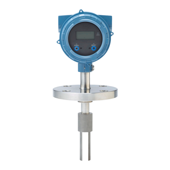
- Page 1 Installation Manual MMI-20020989, Rev AE May 2019 ® Micro Motion Fork Density Meters Direct insertion density meter installation...
- Page 2 Micro Motion employees. Micro Motion will not accept your returned equipment if you fail to follow Micro Motion procedures. Return procedures and forms are available on our web support site at www.emerson.com, or by phoning the Micro Motion Customer Service department.
-
Page 3: Table Of Contents
Installation Manual Contents MMI-20020989 May 2019 Contents Chapter 1 Before you begin......................5 1.1 About this manual..........................5 1.2 Related documentation........................5 Chapter 2 Planning........................7 2.1 Installation checklist......................... 7 2.2 Best practices........................... 8 2.3 Power requirements......................... 8 2.4 Other installation considerations....................10 2.5 Recommended installations for short-stem meters................ - Page 4 Contents Installation Manual May 2019 MMI-20020989 Micro Motion Fork Density Meter...
-
Page 5: Before You Begin
The user is trained in government and corporate safety standards Related documentation You can find all product documentation on the product documentation DVD shipped with the product or at www.emerson.com. See any of the following documents for more information: •... - Page 6 Before you begin Installation Manual May 2019 MMI-20020989 Micro Motion Fork Density Meter...
-
Page 7: Chapter 2 Planning
Installation Manual Planning MMI-20020989 May 2019 Planning Installation checklist □ Verify the contents of the product shipment to confirm that you have all parts and information necessary for the installation. □ Verify that the meter calibration-type code corresponds to the pipe size. If it does not, measurement accuracy may be reduced due to the boundary effect. -
Page 8: Best Practices
Planning Installation Manual May 2019 MMI-20020989 Best practices The following information can help you get the most from your meter. • Handle the meter with care. Follow local practices for lifting or moving the meter. • Perform a Known Density Verification (KDV) check of the meter prior to installing the meter. - Page 9 Installation Manual Planning MMI-20020989 May 2019 Power cable recommendations for explosion-proof/flameproof meters Figure 2-1: Minimum wire gauge (AWG per foot or meter) 2 1 . 6V 24 V 300ft 600ft 900ft 1200ft 1500ft 1800ft 2100ft 2400ft 2700ft 3000ft 91.44m 182.88m 274.32m 365.76m 457.2m 548.64m 640.08m 731.52m 822.96m 914.4m A.
-
Page 10: Other Installation Considerations
Planning Installation Manual May 2019 MMI-20020989 Other installation considerations Numerous external factors can affect the meter's successful operation. To ensure that your system works correctly, consider the factors covered in this section when designing your installation. 2.4.1 Boundary effect Boundary effect refers to the distortion in the wave forms in the process fluid that are caused by reflections from the pipe wall. - Page 11 Installation Manual Planning MMI-20020989 May 2019 but you must avoid more frequent disruptions or serious gas entrainment to ensure accurate and reliable fluid measurement. To minimize the possibility of entrained gas: • Keep pipelines full of fluid at all times. •...
-
Page 12: Recommended Installations For Short-Stem Meters
Planning Installation Manual May 2019 MMI-20020989 for the meter connections are in accordance with the relevant flange standard. Check the latest standards for your connections. For the pressure and temperature limits for Zirconium 702 process connections, see Table 2-1. Table 2-1: Pressure/temperature ratings for Zirconium 702 process connections Process Pressure and temperature ratings flange... - Page 13 Installation Manual Planning MMI-20020989 May 2019 T-piece applications Flow rate 0.5 to 3 m/s at main pipe wall By increasing the insertion depth of the tines into the T-piece, the flow velocity can be increased to 5 m/s for clean fluids. For slurry applications, the maximum flow velocity should be no greater than 4 m/s.
-
Page 14: Perform A Pre-Installation Meter Check
2. Visually inspect the meter for any physical damage. If you notice any physical damage to the meter, immediately contact customer support at flow.support@emerson.com. 3. Position and secure the meter in a vertical position with the flow arrow pointing upward. - Page 15 Installation Manual Planning MMI-20020989 May 2019 Figure 2-4: Power supply wiring terminals A. 24 VDC 5. Perform a Known Density Verification (KDV) check. Use the Known Density Verification procedure to match the current meter calibration with the factory calibration. If the meter passes the test, then it has not drifted or changed during shipment.
- Page 16 Planning Installation Manual May 2019 MMI-20020989 Micro Motion Fork Density Meter...
-
Page 17: Chapter 3 Mounting
Installation Manual Mounting MMI-20020989 May 2019 Mounting If the meter's flow velocity is: • Below 0.3 to 0.5 m/s, install the meter as a free-stream application. • Above 0.3 to 0.5 m/s, install the meter as either a T-piece or flow chamber application. As an alternative, if the pipework can be expanded to reduce the flow velocity to between 0.3 to 0.5 m/s, install a free stream application. - Page 18 Mounting Installation Manual May 2019 MMI-20020989 • Solids drop down • Entrained gas will go up Figure 3-1: Free-stream flanged fitting meter installation A. Use a 4 in (102 mm) pipe for horizontal installations; a 6 in (152 mm) pipe for vertical installations.
- Page 19 Installation Manual Mounting MMI-20020989 May 2019 Procedure Expand the main process pipe using any of the following options. Vertical pipe with concentric reducer Figure 3-2 Horizontal pipe with concentric reducer Figure 3-3 Horizontal pipe with eccentric reducer Figure 3-4 Figure 3-2: Option 1: Vertical pipe with a concentric reducer A.
- Page 20 Mounting Installation Manual May 2019 MMI-20020989 If you use eccentric reducers, the piping must maintain 20 in (508 mm) of upstream straight run (both sides for bidirectional flow applications) to avoid jet effect and a resultant “spray” on the fork tines. 3.1.3 Mount in free-stream application (weldolet fitting) The weldolet for free-stream installations has a 1.5 in (38 mm) taper lock fitting and is...
-
Page 21: T-Piece Applications
Installation Manual Mounting MMI-20020989 May 2019 Figure 3-5: Free-stream (weldolet fitting) meter installation A. 4 in (102 mm) pipe for horizontal installations; 6 in (152 mm) pipe for vertical installations B. 2.1 in (53 mm) meter opening in pipeline C. Weld D. - Page 22 Mounting Installation Manual May 2019 MMI-20020989 • Attach the PFA ring and circlip to the underside of the meter flange before installing the meter in your application (see Attach the PFA ring and circlip). Note If you are using a Zirconium meter, this meter uses a self-locking PFA ring and does not require a circlip.
- Page 23 Installation Manual Mounting MMI-20020989 May 2019 • Entrained gas will go up 2. Size the T-piece so that the meter tines are retracted 1 in (25 mm) from the main pipe wall. For higher flow rates, increase this by 0.4 in (10 mm) for every 1 m/s increase in the main flow rate.
- Page 24 Mounting Installation Manual May 2019 MMI-20020989 Note — Flow velocity at the pipe wall and fluid viscosity must be within the limits shown to ensure that the fluid within the pocket is refreshed in a timely manner. This installation will not respond as rapidly as the free-stream installation to step changes in viscosity.
- Page 25 Installation Manual Mounting MMI-20020989 May 2019 Figure 3-9: 3 in (76 mm) T-piece installation: vertical pipe Insert a purge/drain connection on the side of the T-piece. You can use the purge connection to flush the pipe if necessary. 3.2.3 Mount with a T-piece (weldolet fitting) The weldolet for T-piece installations has a 1.5 in (38 mm) taper lock fitting and is supplied to be welded on 4 in (102 mm), 6 in (152 mm), 8 in (203 mm) or 10 in (254 mm) pipelines.
-
Page 26: Mount With A Flow-Through Chamber
Mounting Installation Manual May 2019 MMI-20020989 Procedure Figure 3-5 for information on installing the meter (with a weldolet fitting) in a T-piece. Size the T-piece so that the meter tines are retracted 1 in (25 mm) from the main pipe wall. - Page 27 Installation Manual Mounting MMI-20020989 May 2019 Important Do not alter the length of the inlet and outlet pipes. Pipe alterations can adversely affect the fitting temperature response and stability. Prerequisites Verify the following conditions: Flow • 5–40 l/min for 2 in (51 mm) Schedule 40 calibration bore section (1.5 - 10.5 gal/min) •...
-
Page 28: Mount In An Open Tank (Long-Stem Meter)
Mounting Installation Manual May 2019 MMI-20020989 Figure 3-11: Flow-through chamber meter installation A. Optional temperature port Note • This flow-through chamber is a direct-insertion type chamber that does not have a thermowell, and uses a 0.75 in (19 mm) Swagelok connection. •... - Page 29 Installation Manual Mounting MMI-20020989 May 2019 Ambient temperature -40 °F (-40.0 °C) to 149 °F (65 °C) Important For an open tank installation, consider the ambient temperature above the tank. Although the meter can operate at 302 °F (150 °C), with an open tank installation, the maximum ambient temperature above the tank is limited to 149 °F (65 °C).
- Page 30 Mounting Installation Manual May 2019 MMI-20020989 Figure 3-13: Meter placement (away from tank wall) A. 2 in (51 mm) B. 7.87 in (200 mm) 3. Confirm the meter tines are immersed in fluid. Figure 3-14: Meter placement (immersed in fluid) 4.
-
Page 31: Mount In A Closed Tank (Long-Stem Meter)
Installation Manual Mounting MMI-20020989 May 2019 Figure 3-16: Meter placement (flow direction through tine gap) 6. Confirm the meter tines are kept away from deposit buildup. Figure 3-17: Meter placement (away from deposit buildup) Mount in a closed tank (long-stem meter) Prerequisites Verify the following conditions: Flow... - Page 32 Mounting Installation Manual May 2019 MMI-20020989 Viscosity • Up to 500 cP (with long tines) • Up to 20,000 cP (with short tines) Fluid temperature -40 °F (-40.0 °C) to 302 °F (150 °C) Ambient temperature -40 °F (-40.0 °C) to 149 °F (65 °C) Important For an open tank installation, consider the ambient temperature above the tank.
- Page 33 Installation Manual Mounting MMI-20020989 May 2019 Figure 3-19: Closed-tank installation (with standoff) A. Standoff height can vary (provided by customer) 3. Confirm the meter tines are away from the tank wall. Figure 3-20: Meter placement (away from tank wall) A. 7.87 in (200 mm) B.
- Page 34 Mounting Installation Manual May 2019 MMI-20020989 Figure 3-21: Meter placement (immersed in fluid) 5. Confirm the meter placement has allowed for the flexing of the tank lid to prevent the meter from being pushed towards a tank wall or into the path of disturbed flow. Figure 3-22: Meter placement (allowance for tank lid flexing) A.
-
Page 35: Attach The Pfa Ring And Circlip
Installation Manual Mounting MMI-20020989 May 2019 Figure 3-24: Meter placement (flow direction through tine gap) 8. Confirm the meter tines are kept away from deposit buildup. Figure 3-25: Meter placement (away from deposit buildup) Attach the PFA ring and circlip You attach the PFA ring (and circlip) around the boss on the underside of the meter flange to center the meter tines within a 2 in (51 mm) Schedule 40 or 80 pipe. -
Page 36: Rotate The Electronics On The Meter (Optional)
Mounting Installation Manual May 2019 MMI-20020989 A. Circlip B. PFA ring C. PFA ring and circlip attached Rotate the electronics on the meter (optional) You can rotate the transmitter on the meter up to 90°. Procedure 1. Using a 4 mm hex key, loosen the cap screw that holds the transmitter in place. Figure 3-26: Component to secure transmitter in place A. -
Page 37: Rotate The Display On The Transmitter (Optional)
Installation Manual Mounting MMI-20020989 May 2019 Rotate the display on the transmitter (optional) The display on the transmitter electronics module can be rotated 90° or 180° from the original position. Figure 3-27: Display components A. Transmitter housing B. Sub-bezel C. Display module D. - Page 38 Mounting Installation Manual May 2019 MMI-20020989 8. Place the display cover onto the main enclosure. 9. Turn the display cover clockwise until it is snug. 10. If appropriate, power up the meter. Micro Motion Fork Density Meter...
-
Page 39: Chapter 4 Wiring
Installation Manual Wiring MMI-20020989 May 2019 Wiring Terminals and wiring requirements Three pairs of wiring terminals are available for transmitter outputs. These outputs vary depending on your transmitter output option ordered. The Analog (mA), Time Period Signal (TPS), and Discrete Output (DO) require external power, and must be connected to an independent 24 VDC power supply. - Page 40 Wiring Installation Manual May 2019 MMI-20020989 Procedure Wire to the appropriate output terminal and pins (see the following figure). mA1+ HART RS-485 A RS-485 RS-485 B A. 24 VDC B. R (250 Ω resistance) load C. HART-compatible host or controller; and/or signal device D.
- Page 41 Installation Manual Wiring MMI-20020989 May 2019 4.2.2 Wire Time Period Signal (TPS) or Discrete Output in explosion-proof/flameproof or non-hazardous area CAUTION Meter installation and wiring should be performed by suitably trained personnel only in accordance with the applicable code of practice. Procedure Wire to the appropriate output terminal and pins (see Figure...
- Page 42 Wiring Installation Manual May 2019 MMI-20020989 Figure 4-1: Wiring the TPS or Discrete Output version mA1+ HART TPS/DO RS-485 A RS-485 RS-485 B A. 24 VDC B. R (250 Ω resistance) load C. HART-compatible host or controller; and/or signal device D.
-
Page 43: Processor Wiring For Remote-Mount 2700 Fieldbus
Installation Manual Wiring MMI-20020989 May 2019 Processor wiring for remote-mount 2700 fieldbus 4.3.1 RS-485 entity parameters for remote-mount 2700 fieldbus DANGER • Hazardous voltage can cause severe injury or death. To reduce the risk of hazardous voltage, shut off power before wiring the meter. •... - Page 44 Wiring Installation Manual May 2019 MMI-20020989 4.3.2 Connect 4-wire cable 4-wire cable types and usage Micro Motion offers two types of 4-wire cable: shielded and armored. Both types contain shield drain wires. The cable supplied by Micro Motion consists of one pair of red and black 18 AWG (0.823 mm²) wires for the VDC connection, and one pair of white and green 22 AWG (0.326 mm²) wires for the RS-485 connection.
- Page 45 Installation Manual Wiring MMI-20020989 May 2019 Prepare a cable with Micro Motion-supplied cable glands Procedure 1. Remove the core processor cover using a flat-blade screw driver. 2. Pass the wires through the gland nut and clamping insert. A. Gland nut B.
- Page 46 Wiring Installation Manual May 2019 MMI-20020989 Option Description A. Shielded heat shrink B. After heat is applied Trim 0.3 in (8 mm). gland type A. Trim 8. Assemble the gland by folding the shield or braid back over the clamping insert and 0.125 in (3 mm) past the O-ring.
- Page 47 Installation Manual Wiring MMI-20020989 May 2019 Figure 4-2: Processor (Modbus/RS-485) connections to the remote-mount 2700 fieldbus transmitter A. White wire to RS-485/A terminal B. Green wire to RS-485/B terminal C. Red wire to Power supply (+) terminal D. Black wire to Power supply (–) terminal Important •...
-
Page 48: Wiring To External Devices (Hart Multidrop)
Wiring Installation Manual May 2019 MMI-20020989 Wiring to external devices (HART multidrop) You can wire up to three external HART devices with the meter. The following information provides wiring diagrams for making those connections in safe and hazardous environments. 4.4.1 Wire mA1 in a HART multi-drop environment Figure 4-3: Wire mA1 in a HART multi-drop environment 24 VDC... -
Page 49: Wiring To Signal Converters And/Or Flow Computers
Installation Manual Wiring MMI-20020989 May 2019 CAUTION • To meet the EC Directive for Electromagnetic Compatibility (EMC), use a suitable instrumentation cable to connect the meter. The instrumentation cable should have individual screens, foil or braid over each twisted pair, and an overall screen to cover all cores. Where permissible, connect the overall screen to earth at both ends (360°... - Page 50 Wiring Installation Manual May 2019 MMI-20020989 4.5.1 Wire to a signal converter in an explosion-proof or non- hazardous area Use this procedure to wire to a signal converter/flow computer in an explosion-proof/ flameproof or non-hazardous area. Figure 4-4: Wiring to a signal converter/flow computer in an explosion-proof/ flameproof or non-hazardous area mA1+ HART...
-
Page 51: Chapter 5 Grounding
Installation Manual Grounding MMI-20020989 May 2019 Grounding The meter must be grounded according to the standards that are applicable at the site. The customer is responsible for knowing and complying with all applicable standards. Prerequisites Use the following guides for grounding practices: •... - Page 52 Grounding Installation Manual May 2019 MMI-20020989 Micro Motion Fork Density Meter...
- Page 53 Installation Manual MMI-20020989 May 2019 Installation Manual...
- Page 54 © 2019 Micro Motion, Inc. All rights reserved. The Emerson logo is a trademark and service mark of Emerson Electric Co. Micro Motion, ELITE, ProLink, MVD and MVD Direct Connect marks are marks of one of the Emerson Automation Solutions family of companies. All other marks are property of their respective owners.
Need help?
Do you have a question about the Micro Motion FDM and is the answer not in the manual?
Questions and answers