
Related Manuals for Emerson Micro Motion LNG Series


Summary of Contents for Emerson Micro Motion LNG Series
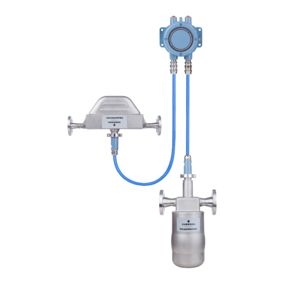
- Page 1 Configuration and Use Manual MMI-20032809, Rev AA February 2017 ® Micro Motion LNG Series Meters...
- Page 2 Safety messages Safety messages are provided throughout this manual to protect personnel and equipment. Read each safety message carefully before proceeding to the next step. Emerson Flow customer service Email: • Worldwide: flow.support@emerson.com • Asia-Pacific: APflow.support@emerson.com Telephone: North and South America...
-
Page 3: Table Of Contents
Contents Contents Part I Getting Started Chapter 1 Before you begin ......................3 About this manual ........................3 Meter model codes ........................3 Communications tools and protocols ..................4 Additional documentation ......................4 Chapter 2 Quick start ........................7 Power up the meter ........................7 Check meter status ........................7 Make a startup connection to the transmitter ................8 Characterize the flowmeter (if required) ..................8... - Page 4 Contents 4.5.2 Configure two-phase flow parameters ................ 31 4.5.3 Configure density damping ..................33 4.5.4 Configure Density Cutoff ....................34 Configure temperature measurement ..................34 4.6.1 Configure Temperature Measurement Unit ................34 4.6.2 Configure Temperature Damping ..................35 Chapter 5 Configure device options and preferences ..............37 Configure response time parameters ..................
- Page 5 Contents Chapter 9 Measurement support ....................61 Options for measurement support .................... 61 Zero the meter .......................... 61 9.2.1 Zero the meter using ProLink III ..................61 9.2.2 Record the zeros ......................63 Validate the meter ........................63 9.3.1 Alternate method for calculating the meter factor for volume flow ......65 Perform a (standard) D1 and D2 density calibration ..............65 9.4.1 Perform a D1 and D2 density calibration using ProLink III ...........
- Page 6 Contents Micro Motion ® LNG Series Meters...
-
Page 7: Getting Started
Getting Started Part I Getting Started Chapters covered in this part: • Before you begin • Quick start Configuration and Use Manual... - Page 8 Getting Started Micro Motion ® LNG Series Meters...
-
Page 9: Before You Begin
• Additional documentation About this manual This manual provides information to help you configure, commission, use, maintain, and troubleshoot the Micro Motion LNG Series meter. Important This manual assumes that the following conditions apply: • The meter has been installed correctly and completely according to the instructions in the installation manual •... -
Page 10: Communications Tools And Protocols
Document Transmitter installation Micro Motion Liquified Natural Gas Dispenser Installation Manual Product Data Sheet Micro Motion LNG Series Meters Product Data Sheet (PDS) Hazardous area installa- See the approval documentation shipped with the transmitter, or tion download the appropriate documentation from the Micro Motion web site at www.micromotion.com. - Page 11 Before you begin All documentation resources are available on the Micro Motion web site at www.micromotion.com.cn or on the Micro Motion user documentation DVD. Configuration and Use Manual...
- Page 12 Before you begin Micro Motion ® LNG Series Meters...
-
Page 13: Chapter 2 Quick Start
Quick start Quick start Topics covered in this chapter: • Power up the meter • Check meter status • Make a startup connection to the transmitter • Characterize the flowmeter (if required) • Verify mass flow measurement • Verify the zero Power up the meter The meter must be powered up for all configuration and commissioning tasks, or for process measurement. -
Page 14: Make A Startup Connection To The Transmitter
Quick start Related information View and acknowledge status alerts Status alerts, causes, and recommendations Make a startup connection to the transmitter Identify the connection type to use, and follow the instructions for that connection type in the appropriate appendix. Communications tool Connection type to use Instructions ProLink III... -
Page 15: Sensor Tags
Quick start 2.4.1 Sensor tags Figure 2-1: Tag on sensors 2.4.2 Density calibration parameters (D1, D2, K1, K2, FD, TC) Density calibration parameters are typically on the sensor tag and the calibration certificate. Verify mass flow measurement Check to see that the mass flow rate reported by the transmitter is accurate. You can use any available method. -
Page 16: Verify The Zero Using Prolink Iii
Quick start The zero verification procedure analyzes the Live Zero value under conditions of zero flow, and compares it to the Zero Stability range for the sensor. If the average Live Zero value is within a reasonable range, the zero value stored in the transmitter is valid. Performing a field calibration will not improve measurement accuracy. -
Page 17: Terminology Used With Zero Verification And Zero Calibration
Quick start Postrequisites Restore normal flow through the sensor by opening the valves. 2.6.2 Terminology used with zero verification and zero calibration Table 2-1: Terminology used with zero verification and zero calibration Term Definition Zero In general, the offset required to synchronize the left pickoff and the right pickoff under conditions of zero flow. - Page 18 Quick start Micro Motion ® LNG Series Meters...
-
Page 19: Part Ii Configuration And Commissioning
Configuration and commissioning Part II Configuration and commissioning Chapters covered in this part: • Introduction to configuration and commissioning • Configure process measurement • Configure device options and preferences • Integrate the meter with the control system Complete the configuration •... - Page 20 Configuration and commissioning Micro Motion ® LNG Series Meters...
-
Page 21: Introduction To Configuration And Commissioning
Introduction to configuration and commissioning Introduction to configuration and commissioning Topics covered in this chapter: • Default values and ranges • Disable write‐protection on the transmitter configuration • Restore the factory configuration Default values and ranges Default values and ranges to view the default values and ranges for the most commonly used parameters. - Page 22 Introduction to configuration and commissioning Restoring the factory configuration is not a common action. You may want to contact Micro Motion to see if there is a preferred method to resolve any issues. Micro Motion ® LNG Series Meters...
-
Page 23: Configure Process Measurement
Configure process measurement Configure process measurement Topics covered in this chapter: • Configure mass flow measurement • Configure volume flow measurement for liquid applications • Configure gas standard volume (GSV) flow measurement • Configure flow direction • Configure density measurement •... - Page 24 Configure process measurement Table 4-1: Options for Mass Flow Measurement Unit Unit description ProLink III label g/sec Grams per second Grams per minute g/min g/hr Grams per hour kg/sec Kilograms per second Kilograms per minute kg/min kg/hr Kilograms per hour kg/day Kilograms per day Metric tons per minute...
-
Page 25: Configure Flow Damping
Configure process measurement Base Time Unit is the existing time unit that the special unit will be based on. Calculate Mass Flow Conversion Factor as follows: a. x base units = y special units b. Mass Flow Conversion Factor = x ÷ y The original mass flow rate value is divided by this value. -
Page 26: Configure Mass Flow Cutoff
Configure process measurement Tips • A high damping value makes the process variable appear smoother because the reported value changes slowly. • A low damping value makes the process variable appear more erratic because the reported value changes more quickly. •... -
Page 27: Configure Volume Flow Measurement For Liquid Applications
Configure process measurement Configure volume flow measurement for liquid applications The volume flow measurement parameters control how liquid volume flow is measured and reported. The volume flow measurement parameters include: Volume Flow Type • Volume Flow Measurement Unit • Volume Flow Cutoff •... - Page 28 Configure process measurement Prerequisites Before you configure Volume Flow Measurement Unit, be sure that Volume Flow Type is set to Liquid. Procedure Set Volume Flow Measurement Unit to the unit you want to use. The default setting for Volume Flow Measurement Unit is l/sec (liters per second). Options for Volume Flow Measurement Unit for liquid applications The transmitter provides a standard set of measurement units for Volume Flow Measurement Unit, plus one user-defined measurement unit.
- Page 29 Configure process measurement Table 4-2: Options for Volume Flow Measurement Unit for liquid applications (continued) Unit description ProLink III label barrels/min Barrels per minute barrels/hr Barrels per hour barrels/day Barrels per day Beer barrels/sec Beer barrels per second Beer barrels/min Beer barrels per minute Beer barrels/hr Beer barrels per hour...
-
Page 30: Configure Volume Flow Cutoff
Configure process measurement Set Volume Total Label to the name you want to use for the volume total and volume inventory unit. The special measurement unit is stored in the transmitter. You can configure the transmitter to use the special measurement unit at any time. You must use ProLink III to select the special measurement unit. -
Page 31: Configure Volume Flow Type For Gas Applications
Configure process measurement • Standard Gas Density Gas Standard Volume Flow Measurement Unit • • Gas Standard Volume Flow Cutoff Restriction You cannot implement both liquid volume flow and gas standard volume flow at the same time. You must choose one or the other. 4.3.1 Configure Volume Flow Type for gas applications ProLink III... -
Page 32: Configure Gas Standard Volume Flow Measurement Unit
Configure process measurement 4.3.3 Configure Gas Standard Volume Flow Measurement Unit ProLink III Device Tools > Configuration > Process Measurement > Flow Overview Gas Standard Volume Flow Measurement Unitspecifies the unit of measure that will be displayed for the gas standard volume flow rate. The measurement unit used for the gas standard volume total and the gas standard volume inventory is derived from this unit. - Page 33 Configure process measurement Table 4-3: Options for Gas Standard Volume Measurement Unit (continued) Unit description ProLink III label SCFH Standard cubic feet per hour SCFD Standard cubic feet per day Sm3/sec Standard cubic meters per second Sm3/min Standard cubic meters per minute Sm3/hr Standard cubic meters per hour Sm3/day...
-
Page 34: Configure Gas Standard Volume Flow Cutoff
Configure process measurement Set Gas Standard Volume Flow Label to the name you want to use for the gas standard volume flow unit. Set Gas Standard Volume Total Label to the name you want to use for the gas standard volume total and gas standard volume inventory unit. -
Page 35: Options For Flow Direction
Configure process measurement Overview Flow Direction controls how forward flow and reverse flow affect flow measurement and reporting. You can configure two flow directions - one flow direction to map to the first group of totals, and a second flow direction to map to the second group of totals. The default flow directions are: Forward for the first group of totals, and Reverse for the second group of totals. -
Page 36: Configure Density Measurement
Configure process measurement Table 4-4: Options for Flow Direction (continued) Flow direction setting from ProLink III Relationship to Flow Direction arrow on sensor Negate Bidirectional Appropriate when both forward and reverse flow are ex- pected, and reverse flow will dominate, but the amount of forward flow will be significant. -
Page 37: Configure Two-Phase Flow Parameters
Configure process measurement Procedure Set Density Measurement Unit to the option you want to use. The default setting for Density Measurement Unit is g/cm3 (grams per cubic centimeter). Options for Density Measurement Unit The transmitter provides a standard set of measurement units for Density Measurement Unit. Different communications tools may use different labels. - Page 38 Configure process measurement Values below this will cause the transmitter to post Alert A105 ( Slug Flow. Gas entrainment can cause your process density to drop temporarily. To reduce the occurrence of two-phase flow alerts that are not significant to your process, set Two-Phase Flow Low Limit slightly below your expected lowest process density.
-
Page 39: Configure Density Damping
Configure process measurement • The two-phase flow alert is deactivated, but remains in the active alert log until it is acknowledged. If the two-phase flow condition does not clear before Two-Phase Flow Timeout expires, the outputs that represent flow rate report a flow rate of 0. If Two-Phase Flow Timeout is set to 0.0 seconds, the outputs that represent flow rate will report a flow rate of 0 as soon as two-phase flow is detected. -
Page 40: Configure Density Cutoff
Configure process measurement 4.5.4 Configure Density Cutoff ProLink III Device Tools > Configuration > Process Measurement > Density Overview Density Cutoff specifies the lowest density value that will be reported as measured. All density values below this cutoff will be reported as 0. Procedure Set Density Cutoff to the value you want to use. -
Page 41: Configure Temperature Damping
Configure process measurement Table 4-7: Options for Temperature Measurement Unit Unit description ProLink III °C Degrees Celsius °F Degrees Fahrenheit °R Degrees Rankine °K Kelvin 4.6.2 Configure Temperature Damping ProLink III Device Tools > Configuration > Temperature Overview Temperature Damping controls the amount of damping that will be applied to the line temperature value, when the on-board temperature data is used (RTD). - Page 42 Configure process measurement Effect of Temperature Damping on process measurement Temperature Damping affects all processes and algorithms that use temperature data from the internal sensor RTD. Temperature compensation Temperature compensation adjusts process measurement to compensate for the effect of temperature on the sensor tubes. Micro Motion ®...
-
Page 43: Configure Device Options And Preferences
Configure device options and preferences Configure device options and preferences Topics covered in this chapter: • Configure response time parameters • Configure alert handling • Configure informational parameters Configure response time parameters You can configure the rate at which process data is polled and process variables are calculated. -
Page 44: Configure Alert Handling
Configure device options and preferences Configure alert handling The alert handling parameters control the transmitter’s response to process and device conditions. • Configure Fault Timeout (Section 5.2.1) • Configure Status Alert Severity (Section 5.2.2) 5.2.1 Configure Fault Timeout ProLink III Device Tools >... - Page 45 Configure device options and preferences Restrictions • For some alerts, Status Alert Severity is not configurable. • For some alerts, Status Alert Severity can be set only to two of the three options. Micro Motion recommends using the default settings for Status Alert Severity unless you have a specific requirement to change them.
-
Page 46: Configure Informational Parameters
Configure device options and preferences Table 5-1: Status alerts and Status Alert Severity (continued) Alert code Status message Default severity Notes Configurable? Fault A005 Mass Flow Rate Overrange A006 Characterization Required Fault Fault A008 Density Overrange Fault A009 Transmitter Initializing/ Warming Up A010 Calibration Failure... -
Page 47: Configure The Rtd Cable Length
Configure device options and preferences You can configure the sensor index only if the connection is through a service port. If the connection is an RS-485 port, the sensor index is read-only, with each Modbus address corresponding to a different sensor. In default, Modbus address 1 corresponds to sensor 1, Modbus address 2 corresponds to sensor 2. -
Page 48: Configure Sensor Liner Material
Configure device options and preferences Overview Sensor Material lets you store the type of material used for your sensor’s wetted parts in transmitter memory. This parameter is not used in processing and is not required. Procedure Obtain the material used for your sensor’s wetted parts from the documents shipped with your sensor, or from a code in the sensor model number. -
Page 49: Configure Descriptor
Configure device options and preferences 5.3.7 Configure Descriptor ProLink III Device Tools > Configuration > Informational Parameters > Transmitter Overview Descriptor lets you store a description in transmitter memory. The description is not used in processing and is not required. Procedure Enter a description for the transmitter or device You can use up to 16 characters for the description. - Page 50 Configure device options and preferences Micro Motion ® LNG Series Meters...
-
Page 51: Integrate The Meter With The Control System
Integrate the meter with the control system Integrate the meter with the control system Topics covered in this chapter: • Configure events • Configure digital communications Configure events An event occurs when the real-time value of a user-specified process variable moves past a user-defined setpoint. -
Page 52: Configure Digital Communications
Integrate the meter with the control system Options Description x ≤ A or x ≥ B The event occurs when the value of the assigned process variable (x) is out of range, that is, less than Setpoint A or greater than Setpoint B, end- points included. -
Page 53: Configure Modbus/Rs-485 Communications
Integrate the meter with the control system 6.2.1 Configure Modbus/RS-485 communications ProLink III Device Tools > Configuration > Communications > Communications (Modbus) Overview Modbus/RS-485 communications parameters control Modbus communication with the transmitter's RS-485 terminals. Modbus/RS-485 communications parameters include: • Modbus Address (Slave Address) Floating-Point Byte Order •... -
Page 54: Configure Rs-485 Terminals
Integrate the meter with the control system Additional Communications Response Delay is used to synchronize Modbus communications with hosts that operate at a slower speed than the transmitter. The value specified here will be added to each response the transmitter sends to the host. -
Page 55: Configure Digital Communications Fault Action
Integrate the meter with the control system 6.2.3 Configure Digital Communications Fault Action ProLink III Device Tools > Configuration > Fault Processing Overview Digital Communications Fault Actionspecifies the values that will be reported via digital communications if the device encounters an internal fault condition. Procedure Set Digital Communications Fault Action as desired. - Page 56 Integrate the meter with the control system Micro Motion ® LNG Series Meters...
-
Page 57: Complete The Configuration
Complete the configuration Complete the configuration Topics covered in this chapter: • Back up transmitter configuration • Enable write‐protection on the transmitter configuration Back up transmitter configuration ProLink III provides a configuration upload/download function which allows you to save configuration sets to your PC. This allows you to back up and restore your transmitter configuration. - Page 58 Complete the configuration Micro Motion ® LNG Series Meters...
-
Page 59: Part Iii Operations, Maintenance, And Troubleshooting
Operations, maintenance, and troubleshooting Part III Operations, maintenance, and troubleshooting Chapters covered in this part: • Transmitter operation • Measurement support • Troubleshooting Configuration and Use Manual... - Page 60 Operations, maintenance, and troubleshooting Micro Motion ® LNG Series Meters...
-
Page 61: Chapter 8 Transmitter Operation
Transmitter operation Transmitter operation Topics covered in this chapter: • Custody transfer • Record the process variables • View process variables • View transmitter status using the status LED • View and acknowledge status alerts • Read totalizer and inventory values •... -
Page 62: View Process Variables
Transmitter operation Measurement Variable Typical average Typical high Typical low Flow rate Density Temperature Tube frequency Pickoff voltage Drive gain View process variables ProLink III View the desired variable on the main screen under Process Variables. See Section 8.3.1for more information. Overview Process variables provide information about the state of the process fluid, such as flow rate, density, and temperature, as well as running totals. -
Page 63: View And Acknowledge Status Alerts
Transmitter operation To interpret the status LED, see the following table. Restriction If LED Blinking is disabled, the status LED will flash only during calibration. It will not flash to indicate an unacknowledged alarm. Table 8-1: Status LED states LED behavior Alarm condition Description Solid green... -
Page 64: Alert Data In Transmitter Memory
Transmitter operation Notes • All fault alerts are displayed in the Failed: Fix Now category. • All information alerts are displayed in either the Maintenance: Fix Soon category or the Advisory: Informational category. The category assignment is hard-coded. • The transmitter automatically filters out alerts with Alert Severity set to Ignore. To acknowledge a single alert, check the Ack checkbox for that alert. -
Page 65: Read Totalizer And Inventory Values
Transmitter operation Table 8-2: Alert data in transmitter memory (continued) Transmitter action if condition occurs Alert data structure Contents Clearing Recent Alerts 50 most recent alert postings or alert clearings Not cleared; maintained across transmitter power cycles Read totalizer and inventory values ProLink III View the desired variable on the main screen under Process Variables. -
Page 66: Reset Totalizers
Transmitter operation Reset totalizers ProLink III Device Tools > Totalizer Control > Totalizer and Inventories > Reset Mass Total Device Tools > Totalizer Control > Totalizer and Inventories > Reset Volume Total Device Tools > Totalizer Control > Totalizer and Inventories > Reset Gas Total Device Tools >... -
Page 67: Chapter 9 Measurement Support
Measurement support Measurement support Topics covered in this chapter: • Options for measurement support • Zero the meter • Validate the meter • Perform a (standard) D1 and D2 density calibration Options for measurement support Micro Motion provides several measurement support procedures to help you evaluate and maintain your flowmeter's accuracy. - Page 68 Measurement support • The stored zero value fails the zero verification procedure. Prerequisites Before performing a field zero, execute the Zero Verification procedure to see whether or not a field zero can improve measurement accuracy. Important Do not verify the zero or zero the meter if a high-severity alert is active. Correct the problem, then verify the zero or zero the meter.
-
Page 69: Record The Zeros
Measurement support Need help? If the zero fails: • Ensure that there is no flow through the sensor, then retry. • Set Zero Time to a lower value, then retry. • If you want to return the flowmeter to operation using a previous zero value: To restore the zero value set at the factory: Device Tools >... - Page 70 Measurement support Prerequisites Identify the meter factor(s) that you will calculate and set. You may set any combination of the three meter factors: mass flow, volume flow, and density. Note that all three meter factors are independent: • The meter factor for mass flow affects only the value reported for mass flow. •...
-
Page 71: Alternate Method For Calculating The Meter Factor For Volume Flow
Measurement support The first meter factor for mass flow is 0.9989. One year later, the flowmeter is validated again. The mass flow measurement from the transmitter is 250.07 lb. The mass flow measurement from the reference device is 250.25 lb. The new mass flow meter factor is calculated as follows: 250.25 MeterFactor = 0.9989... -
Page 72: Perform A D1 And D2 Density Calibration Using Prolink Iii
Measurement support Important Micro Motion flowmeters are calibrated at the factory, and normally do not need to be calibrated in the field. Calibrate the flowmeter only if you must do so to meet regulatory requirements. Contact Micro Motion before calibrating the flowmeter. Micro Motion recommends using meter validation and meter factors, rather than calibration, to prove the meter against a regulatory standard or to correct measurement error. - Page 73 Measurement support Figure 9-1: D1 and D2 density calibration using ProLink III Configuration and Use Manual...
- Page 74 Measurement support Micro Motion ® LNG Series Meters...
-
Page 75: Chapter 10 Troubleshooting
Troubleshooting Troubleshooting Topics covered in this chapter: • Status LED states • Status alerts, causes, and recommendations • Flow measurement problems • Density measurement problems • Temperature measurement problems • Check power supply wiring • Check grounding • Check for radio frequency interference (RFI) •... -
Page 76: Status Alerts, Causes, And Recommendations
Troubleshooting 10.2 Status alerts, causes, and recommendations Alert num- Alert title Possible cause Recommended actions A001 EEPROM Error The transmitter has detected a • Cycle power to the meter. problem communicating with the • Replace the core processor. sensor. • Contact Micro Motion. - Page 77 Troubleshooting Alert num- Alert title Possible cause Recommended actions A008 Density Overrange The line density is greater than • If other alerts are present, resolve those 10 g/cm (10000 kg/m alert conditions first. If the current alert persists, continue with the recommen- ded actions.
- Page 78 Troubleshooting Alert num- Alert title Possible cause Recommended actions A011 Zero Calibration Many possible causes, such as too • Verify that there is no flow through the Failed: Low much flow, especially reverse flow, sensor, cycle power to the meter, then through the sensor during a calibra- retry the procedure.
- Page 79 Troubleshooting Alert num- Alert title Possible cause Recommended actions A020 Calibration Factors Some calibration factors have not • Verify all of the characterization or cali- Missing been entered or are incorrect. bration parameters. See the sensor tag or the calibration sheet for your meter. •...
- Page 80 Troubleshooting Alert num- Alert title Possible cause Recommended actions A102 Drive Overrange The drive power (current/voltage) is • Check the drive gain and the pickoff at its maximum. voltage. • Check the wiring between the sensor and the transmitter. • Verify that internal wiring is secure and that there are no internal electrical problems.
-
Page 81: Flow Measurement Problems
Troubleshooting 10.3 Flow measurement problems Table 10-2: Flow measurement problems and recommended actions Problem Possible causes Recommended actions Non-zero flow reading • Misaligned piping (especially in new instal- • If the reading is not excessively high, re- at no-flow conditions lations) view the live zero. - Page 82 Troubleshooting Table 10-2: Flow measurement problems and recommended actions (continued) Problem Possible causes Recommended actions Erratic non-zero flow • Two-phase flow • Verify that the sensor orientation is appro- rate when flow is • Damping value too low priate for your application (refer to the steady •...
-
Page 83: Density Measurement Problems
Troubleshooting 10.4 Density measurement problems Table 10-3: Density measurement problems and recommended actions Problem Possible causes Recommended actions Inaccurate density • Problem with process fluid • Check your process conditions against the reading • Incorrect density calibration factors values reported by the device. •... -
Page 84: Temperature Measurement Problems
Troubleshooting 10.5 Temperature measurement problems Table 10-4: Temperature measurement problems and recommended actions Problem Possible causes Recommended actions Temperature reading • RTD failure • Check junction box for moisture or verdi- significantly different • Incorrect compensation factors gris. from process temper- •... -
Page 85: Check Grounding
Troubleshooting • If there is no power, continue with this procedure. Before inspecting the power supply wiring, disconnect the power source. CAUTION! If the transmitter is in a hazardous area, wait five minutes after disconnecting the power. Ensure that the terminals, wires, and wiring compartment are clean and dry. Ensure that the power supply wires are connected to the correct terminals. -
Page 86: Check For Two-Phase Flow (Slug Flow)
Troubleshooting Do not terminate the shielding inside the wiring compartment. 360-degree termination of shielding is unnecessary. • Eliminate the RFI source. 10.9 Check for two-phase flow (slug flow) Two-phase flow can cause rapid changes in the drive gain. This can cause a variety of measurement issues. -
Page 87: Collect Drive Gain Data
Troubleshooting Table 10-5: Possible causes and recommended actions for excessive (saturated) drive gain (continued) Possible cause Recommended actions Bent sensor tube Check the pickoff voltages (see Section 10.11). If either of them are close to zero (but neither is zero), the sensor tubes may be bent. -
Page 88: Collect Pickoff Voltage Data
Troubleshooting To know whether your pickoff voltage is unusually low, you must collect pickoff voltage data during the problem condition and compare it to pickoff voltage data from a period of normal operation. Table 10-7: Possible causes and recommended actions for low pickoff voltage Possible cause Recommended actions Faulty wiring runs between the sensor... -
Page 89: Check The Sensor Coils
Troubleshooting Table 10-8: Possible causes and recommended actions for electrical shorts (continued) Possible cause Recommended action Internally shorted feedthrough Contact Micro Motion. Faulty cable Replace the cable. Improper wire termination Verify wire terminations inside the sensor junction box. The Micro Motion document titled 9‐Wire Flowmeter Cable Prep‐ aration and Installation Guide may offer some assistance. - Page 90 Troubleshooting There should be no open circuits, that is, no infinite resistance readings. The left pickoff and right pickoff readings should be the same or very close (±5 Ω. If there are any unusual readings, repeat the coil resistance tests at the sensor junction box to eliminate the possibility of faulty cable.
-
Page 91: Appendix A Using Prolink Iii With The Transmitter
Using ProLink III with the transmitter Appendix A Using ProLink III with the transmitter Connect with ProLink III A connection from ProLink III to your transmitter allows you to read process data, configure the transmitter, and perform maintenance and troubleshooting tasks. A.1.1 Connection types supported by ProLink III Different connection types are available for connecting from ProLink III to the transmitter. -
Page 92: Connect With Prolink Iii To The Rs-485 Port
Using ProLink III with the transmitter Service port connections use standard connection parameters and a standard address. You do not need to configure them here. Set the PC Port value to the PC COM port that you are using for this connection. Click Connect. - Page 93 Using ProLink III with the transmitter Table A-1: Default Modbus/RS-485 connection parameters Parameter Default value Protocol Modbus RTU Baud 9600 Parity None Stop Bits Address 1 (sensor1 ), 2 (sensor2) Set the PC Port value to the PC COM port that you are using for this connection. Click Connect.
- Page 94 Using ProLink III with the transmitter Micro Motion ® LNG Series Meters...
-
Page 95: Appendix B Default Values And Ranges
Default values and ranges Appendix B Default values and ranges Default values and ranges The default values and ranges represent the typical factory transmitter configuration. Depending on how the transmitter was ordered, certain values may have been configured at the factory and are not represented in the default values and ranges. Table B-1: Transmitter default values and ranges Type... - Page 96 Default values and ranges Table B-1: Transmitter default values and ranges (continued) Type Parameter Default Range Comments Density Density damping 1.28 sec 0.0 – 60.0 sec User-entered value is corrected to nearest value in list of preset values. Density units g/cm Density cutoff 0.2 g/cm...
- Page 97 Default values and ranges Table B-1: Transmitter default values and ranges (continued) Type Parameter Default Range Comments Digital com- Fault action None munications Fault timeout 0 seconds 0.0 – 60.0 sec Modbus address 1 (sensor 1) 1 ~127, ex- Address 1 or any other modified cluding 111 address will always correspond 2 (sensor 2)
- Page 98 Default values and ranges Micro Motion ® LNG Series Meters...
- Page 99 Default values and ranges Configuration and Use Manual...
- Page 100 © Micro Motion Japan 2017 Micro Motion, Inc. All rights reserved. Emerson Automation Solutions The Emerson logo is a trademark and service mark of Emerson 1-2-5, Higashi Shinagawa Electric Co. Micro Motion, ELITE, ProLink, MVD and MVD Direct Shinagawa-ku Connect marks are marks of one of the Emerson Automation Tokyo 140-0002 Japan Solutions family of companies.
Need help?
Do you have a question about the Micro Motion LNG Series and is the answer not in the manual?
Questions and answers