Table of Contents
Advertisement
Quick Links
g
GE Power Management
215 Anderson Avenue, Markham, Ontario
Canada L6E 1B3
Tel: (905) 294-6222 Fax: (905) 294-8512
Internet: http://www.GEindustrial.com/pm
MOTOR MANAGEMENT RELAY
Instruction Manual
469 Firmware Revision: 30E281.000
469PC Software Revision: 2.8x
Manual P/N: 1601-0057-D9 (GEK-106289A)
Copyright © 2001 GE Power Management
SR469 STATUS
MOTOR STATUS
SR469 IN SERVICE
STOPPED
SETPOINT ACCESS
STARTING
COMPUTER RS232
RUNNING
COMPUTER RS485
OVERLOAD PICKUP
AUXILIARY RS485
UNBALANCE PICKUP
LOCKOUT
GROUND PICKUP
RESET
HOT RTD
POSSIBLE
RESET
MESSAGE
LOSS OF LOAD
NEXT
PROGRAM PORT
7
SETPOINT
MESSAGE
4
ACTUAL
1
ESCAPE
VALUE
.
ENTER
469
Motor Management Relay®
GE Power Management
469
OUTPUT RELAYS
R1 TRIP
R2 AUXILIARY
R3 AUXILIARY
R4 ALARM
R5 BLOCK START
R6 SERVICE
8
9
5
6
2
3
0
HELP
806766A5.CDR
®
Manufactured under an
ISO9001 Registered system.
Advertisement
Table of Contents

Related Manuals for GE MOTOR MANAGEMENT RELAY 469


Summary of Contents for GE MOTOR MANAGEMENT RELAY 469
- Page 1 GE Power Management ® MOTOR MANAGEMENT RELAY Instruction Manual 469 Firmware Revision: 30E281.000 469PC Software Revision: 2.8x Manual P/N: 1601-0057-D9 (GEK-106289A) Copyright © 2001 GE Power Management SR469 STATUS MOTOR STATUS OUTPUT RELAYS SR469 IN SERVICE STOPPED R1 TRIP SETPOINT ACCESS...
- Page 3 WARNING These instructions do not purport to cover all details or variations in equipment nor provide for every possible contingency to be met in connection with installation, operation, or maintenance. Should further information be desired or should particular problems arise which are not covered sufficiently for the purchaser’s purpose, the matter should be referred to the General Electric Company.
-
Page 5: Table Of Contents
OUTPUT RELAY LED INDICATORS ............3-3 3.1.4 RS232 PROGRAM PORT ................. 3-3 3.1.5 KEYPAD ....................3-4 3.1.6 ENTERING ALPHANUMERIC TEXT............3-4 3.1.7 ENTERING +/– SIGNS ................3-4 3.2 SETPOINT ENTRY 3.2.1 PROCEDURE .................... 3-5 GE Power Management 469 Motor Management Relay... - Page 6 4.4.19 DIGITAL INPUT FUNCTION: CAPTURE TRACE ........4-23 4.4.20 DIGITAL INPUT FUNCTION: SIMULATE PRE-FAULT ......4-23 4.4.21 DIGITAL INPUT FUNCTION: SIMULATE FAULT ........4-23 4.4.22 DIGITAL INPUT FUNCTION: SIMULATE PRE-FAULT…FAULT ... 4-23 4.5 S4 OUTPUT RELAYS 4.5.1 DESCRIPTION ..................4-24 469 Motor Management Relay GE Power Management...
- Page 7 4.10.4 FREQUENCY ..................4-65 4.11 S10 POWER ELEMENTS 4.11.1 POWER MEASUREMENT CONVENTIONS ........... 4-66 4.11.2 POWER FACTOR..................4-67 4.11.3 REACTIVE POWER ................4-68 4.11.4 UNDERPOWER..................4-69 a FUNCTION ....................4-69 b EXAMPLE ....................4-69 GE Power Management 469 Motor Management Relay...
- Page 8 TORQUE ALARM MESSAGE ..............5-12 5.3.7 DEMAND METERING ................5-13 5.3.8 ANALOG INPUTS ..................5-14 5.3.9 PHASORS ....................5-15 5.4 A3 LEARNED DATA 5.4.1 MOTOR STARTING ................5-17 5.4.2 AVERAGE MOTOR LOAD ..............5-17 469 Motor Management Relay GE Power Management...
- Page 9 USER DEFINABLE MEMORY MAP AREA ..........6-16 6.4.3 EVENT RECORDER ................6-17 6.4.4 WAVEFORM CAPTURE................6-17 6.4.5 469 MEMORY MAP ................. 6-18 6.4.6 469 MEMORY MAP FORMAT CODES ........... 6-61 7. TESTING 7.1 OVERVIEW 7.1.1 TEST SETUP..................... 7-1 GE Power Management 469 Motor Management Relay...
- Page 10 GROUND (1A/5A) AND DIFFERENTIAL ACCURACY TEST ....7-3 a 5 A INPUT ....................7-3 b 1 A INPUT ....................7-3 7.2.4 GE POWER MANAGEMENT 50:0.025 GROUND ACCURACY TEST ..7-4 7.2.5 RTD ACCURACY TEST ................7-4 7.2.6 DIGITAL INPUTS AND TRIP COIL SUPERVISION ........7-6 7.2.7...
- Page 11 E. APPENDIX E E.1 FIGURES AND TABLES E.1.1 LIST OF FIGURES ..................E-1 E.1.2 LIST OF TABLES..................E-3 F. APPENDIX F F.1 EU DECLARATION OF CONFORMITY G. WARRANTY G.1 WARRANTY INFORMATION G.1.1 WARRANTY ....................G-1 GE Power Management 469 Motor Management Relay...
-
Page 13: Introduction
Figure 1–1: SINGLE LINE DIAGRAM Typical applications include: • Pumps • Fans • Compressors • Mills • Shredders • Extruders • Debarkers • Refiners • Cranes • Conveyors • Chillers • Crushers • Blowers GE Power Management 469 Motor Management Relay... - Page 14 Ground faults or earth leakage as low as 0.25 A may be detected using the GE Power Management 50:0.025 Ground CT. CT inputs for phase differential protection are also provided. The 12 RTD inputs provided may be individually field programmed for different RTD types. Volt- age transformer inputs allow for numerous protection features based on voltage and power quantities.
- Page 15 Trip coil supervision Apparent power and kVA demand Flash memory for easy firmware updates Reactive power, kvar demand, kvar consumption/ generation Frequency Power Factor Speed in RPM with a key phasor input User-programmable analog inputs GE Power Management 469 Motor Management Relay...
-
Page 16: Order Information
The 469 differential CT inputs are field programmable for CTs with 1 A or 5 A secondaries. There are two ground CT inputs, one for the GE Power Management 50:0.025 core balance CT and one for a ground CT with a 1 A or 5 A secondary, also field programmable. -
Page 17: Specifications
1.00 to 150.00:1 in steps of 0.01 VT Secondary: 273 V AC (full scale) Conversion Range: 0.05 to 1.00 × full scale Accuracy: ±0.5% of full scale Max. Continuous: 280 V AC Burden: > 500 kΩ GE Power Management 469 Motor Management Relay... - Page 18 Pickup Accuracy: as per Phase Current Inputs Timing Accuracy: ±0.5 s or ±0.5% of total time Timing Accuracy: ±100 ms or ±2% of total time Elements: Trip and Alarm Elements: Trip and Alarm 469 Motor Management Relay GE Power Management...
- Page 19 1 to 250°C in steps of 1 Elements: Trip Pickup Hysteresis:2°C Time Delay: LOAD SHED Elements: Trip and Alarm Configurable: Assignable to Digital Inputs1 to 4 Timing Accuracy: 100 ms max. Elements: Trip GE Power Management 469 Motor Management Relay...
- Page 20 Trip and Alarm Range: 0 to 2000000.000 MW·hours. Timing Accuracy: ±0.5% Update Rate: 5 seconds METERED REACTIVE POWER CONSUMPTION Description: Continuous total of reactive power consumption. Range: 0 to 2000000.000 Mvar·hours Timing Accuracy: ±0.5% 469 Motor Management Relay GE Power Management...
- Page 21 CSA: CSA approved CASE CE: Conforms to EN 55011/CISPR 11, EN 50082-2 Fully drawout (automatic CT shorts) Conforms to IEC 947-1,1010-1 Seal provision Dust tight door Panel or 19" rack mount IP Class: IP20-X GE Power Management 469 Motor Management Relay...
-
Page 23: Installation
2 INSTALLATION 2.1 MECHANICAL 2.1.1 DESCRIPTION The 469 is packaged in the standard GE Power Management SR series arrangement, which consists of a dra- wout unit and a companion fixed case. The case provides mechanical protection to the unit and is used to make permanent connections to all external equipment. -
Page 24: Product Identification
• MANUFACTURE DATE • PHASE CURRENT INPUTS • SPECIAL NOTES • OVERVOLTAGE CATEGORY • INSULATION VOLTAGE • POLLUTION DEGREE • CONTROL POWER • OUTPUT CONTACT RATING Figure 2–3: CASE AND UNIT IDENTIFICATION LABELS 469 Motor Management Relay GE Power Management... -
Page 25: Installation
(to a horizontal position) from each side of the case as shown below. The case is now securely mounted, ready for panel wiring. If additional support is desired, the SR optional mounting kit may be ordered. Figure 2–5: BEND UP MOUNTING TABS GE Power Management 469 Motor Management Relay... -
Page 26: Unit Withdrawal And Insertion
3. While holding the latch raised, grasp the locking handle in the center and pull firmly, rotating the handle up from the bottom of the unit until movement ceases. Figure 2–7: ROTATE HANDLE TO STOP POSITION 469 Motor Management Relay GE Power Management... - Page 27 5. When the unit is fully inserted, the latch will be heard to click, locking the handle in the final position. No special ventilation requirements need to be observed during the installation of the unit. The unit does not require cleaning. CAUTION GE Power Management 469 Motor Management Relay...
-
Page 28: Terminal Locations
2.1 MECHANICAL 2 INSTALLATION 2.1.5 TERMINAL LOCATIONS Figure 2–9: TERMINAL LAYOUT 469 Motor Management Relay GE Power Management... - Page 29 RTD #12 HOT PHASE B CT STARTER STATUS PHASE C CT EMERGENCY RESTART 1A/5A GROUND CT REMOTE RESET 50:0.025 GROUND CT ASSIGNABLE SW. 01 CONTROL POWER – ASSIGNABLE SW. 02 CONTROL POWER + GE Power Management 469 Motor Management Relay...
-
Page 30: Electrical
2.2 ELECTRICAL 2 INSTALLATION 2.2 ELECTRICAL 2.2.1 TYPICAL WIRING DIAGRAM Figure 2–10: TYPICAL WIRING DIAGRAM 469 Motor Management Relay GE Power Management... -
Page 31: Typical Wiring
Transient energy must be conducted back to the source through the filter ground terminal. A separate safety ground terminal is provided for hi-pot testing. All grounds MUST be hooked up for normal operation regardless of control power supply type. WARNING GE Power Management 469 Motor Management Relay... -
Page 32: Phase Current Inputs
For example, in mining applications where earth leakage current must be measured for personnel safety, primary ground current as low as 0.25 A may be detected with the GE Power Management 50:0.025 CT. Only one ground CT input tap should be used on a given unit. - Page 33 (see Section 1.2: SPECIFICATIONS on page 1–5). The 469 measures up to 25 A of primary ground current if this tap is used in conjunction with the GE Power Management core balance CT. The zero-sequence connection is recommended. Unequal saturation of CTs, size and location of motor, resistance of power system and motor core saturation density, etc., may cause false...
-
Page 34: Differential Current Inputs
CT polarity is important. The summation method may also be implemented using the phase CTs as shown below. They will have to have the same CT ratio. Figure 2–14: CORE BALANCE METHOD WITHOUT PHASE CTs WITH PHASE CTs Figure 2–15: SUMMATION METHOD 2-12 469 Motor Management Relay GE Power Management... -
Page 35: Voltage Inputs
Refer to Section 1.2: SPECIFICATIONS on page 1–5 for maximum current draw from the +24 V DC switch supply. DO NOT INJECT VOLTAGES TO DIGITAL INPUTS. DRY CONTACT CONNECTIONS ONLY. CAUTION GE Power Management 469 Motor Management Relay 2-13... -
Page 36: Analog Inputs
= 5 V / 0.001 A = 5000 Ω. For 4 to 20 mA, this resistor would be scale is required to correspond to 1 mA, R load = 5 V / 0.020 A = 250 Ω. load 2-14 469 Motor Management Relay GE Power Management... -
Page 37: Rtd Sensor Connections
IMPORTANT: The RTD circuitry is isolated as a group with the Analog Input circuitry and the Analog Output circuitry. Only one ground reference should be used for the three circuits. Transorbs limit this isolation to ±36 V with respect to the 469 safety ground. NOTE GE Power Management 469 Motor Management Relay 2-15... -
Page 38: Reduced Rtd Lead Number Application
2. If the RTD Return lead to the 469 or any of the jumpers break, all RTDs from the point of the break will read open. 3. If the Compensation lead or any of the jumpers break, all RTDs from the point of the break will function without any lead compensation. 2-16 469 Motor Management Relay GE Power Management... -
Page 39: Two Wire Rtd Lead Compensation
469 causes significant errors as two or more parallel paths for the return current have been created. Use of this wiring scheme causes errors in readings equivalent to that in the REDUCED RTD LEAD NUMBER application described earlier. Figure 2–21: RTD ALTERNATE GROUNDING GE Power Management 469 Motor Management Relay 2-17... -
Page 40: Output Relays
See Figure 2–22: ALTERNATE WIRING FOR CONTACTORS on page 2–19 for details. 2-18 469 Motor Management Relay GE Power Management... -
Page 41: Drawout Indicator
The Drawout Indicator is simply a jumper from terminals E12 to F12. When the 469 is withdrawn from the case, terminals E12 and F12 are open. This may be useful for differentiating between loss of control power as indi- cated by the R6 SERVICE relay and withdrawal of the unit. GE Power Management 469 Motor Management Relay 2-19... -
Page 42: Rs485 Communications Ports
1 nF capacitor across the ‘+’ and ‘–’ terminals. Observing these guidelines provides a reliable communication system immune to system transients. 469 Motor Management Relay 469 Motor Management Relay 469 Motor Management Relay Figure 2–23: RS485 COMMUNICATIONS INTERFACE 2-20 469 Motor Management Relay GE Power Management... -
Page 43: Typical 2 Speed Motor Wiring
2 INSTALLATION 2.2 ELECTRICAL 2.2.15 TYPICAL 2 SPEED MOTOR WIRING GE Power Management 469 Motor Management Relay 2-21... -
Page 44: Dielectric Strength Testing
(less than 30 V), RTDs, analog inputs, analog outputs, digital inputs, and RS485 communication ports are not to be tested for dielectric strength under any circumstance (see below). Figure 2–24: TESTING THE 469 FOR DIELECTRIC STRENGTH 2-22 469 Motor Management Relay GE Power Management... -
Page 45: Operation
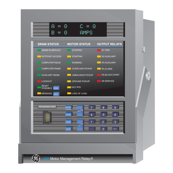
R5 BLOCK START R6 SERVICE LOCKOUT GROUND PICKUP RESET HOT RTD POSSIBLE RESET MESSAGE LOSS OF LOAD NEXT PROGRAM PORT SETPOINT MESSAGE ACTUAL ESCAPE VALUE HELP ENTER Motor Management Relay® 806766A5.CDR Figure 3–1: 469 FACEPLATE GE Power Management 469 Motor Management Relay... -
Page 46: Display
MESSAGE: Flashes when a trip, alarm, or start block occurs. Pressing the NEXT key scrolls through diagnostic messages. This LED remains solid when setpoint and actual value messages are being viewed. Pressing the NEXT key returns the display to the default messages. 469 Motor Management Relay GE Power Management... -
Page 47: Motor Status Led Indicators
469PC software. Local interrogation of setpoints and actual values is also possible. New firmware may also be downloaded to the 469 flash memory through this port. Upgrading of the relay firmware does not require a hardware EPROM change. GE Power Management 469 Motor Management Relay... -
Page 48: Keypad
VALUE VALUE • After entering at least one digit of a numeric setpoint value, pressing the keys will change the sign of the value where applicable. 469 Motor Management Relay GE Power Management... -
Page 49: Setpoint Entry
HASE BEEN STORED and the display returns to SETPOINT ACCESS: PERMITTED 6. Press ESCAPE to exit the subgroup. Pressing ESCAPE numerous times will always returns the cursor to the top of the page. GE Power Management 469 Motor Management Relay... -
Page 51: Overview
This scenario might occur if someone shorts across the block terminals and overrides the 469 protection to start the motor. GE Power Management 469 Motor Management Relay... -
Page 52: Relay Assignment Practices
Short Circuit Backup Trip default to R1 TRIP output relay. All alarms default to the R4 ALARM relay. Only special control functions are defaulted to the R2 and R3 AUXILIARY relays. It is recom- mended that these assignments be reviewed once all the setpoints have been programmed. 469 Motor Management Relay GE Power Management... -
Page 53: Setpoint Message Map
S ANALOG INPUT 2 S COMM PORT MONITOR S PHASE DIFFERENTIAL S ANALOG INPUT 3 S GE USE ONLY S ANALOG INPUT 4 S ANALOG IN 1-2 DIFF S ANALOG IN 3-4 DIFF2 † ASSIGNABLE INPUT 4 dedicated as two-speed monitor if the Two-Speed Motor feature is used. The two-speed motor protection is enabled in S2 SYSTEM SETUP \ CURRENT SENSING. -
Page 54: S1 469 Setup
If an invalid passcode is entered, an encrypted passcode may be viewed by pressing the key. Consult the factory service department with this number if the currently programmed passcode is unknown. Using a deciphering program, the passcode can be determined. 469 Motor Management Relay GE Power Management... -
Page 55: Preferences
This value can be used as the starting point for the motor load filter interval. Additional fine tuning may be required. WARNING: This averaging may increase trip/alarm times by 16.7 ms for every cycle averaged. GE Power Management 469 Motor Management Relay... -
Page 56: Serial Ports
1 stop bits, while parity is optional. The computer RS485 port is a general purpose port for connec- tion to a DCS, PLC, or PC. The auxiliary RS485 port may be used for redundancy or, it may be used to talk to auxiliary GE Power Management devices. 4.2.4 REAL TIME CLOCK S REAL TIME CLOCK ð... -
Page 57: Default Messages
4. Press ENTER to remove the current message out of the default message list. 5. If the procedure was followed correctly, the following flash message will be displayed: DEFAULT MESSAGE HAS BEEN REMOVED GE Power Management 469 Motor Management Relay... -
Page 58: Message Scratchpad
ESCAPE 5. When the desired message is displayed press ENTER to store or to quit. The message is now per- ESCAPE manently stored. Press to cancel the altered message. 469 Motor Management Relay GE Power Management... -
Page 59: Clear Data
• CLEAR EVENT RECORD: The event recorder saves the last 40 events, automatically overwriting the oldest event. If desired, this command can clear all events to prevent confusion with old information. GE Power Management 469 Motor Management Relay... -
Page 60: Installation
RESET STARTER INFORMATION: The total number of starter operations can be viewed in actual values. On a new installation or if maintenance work is done on the breaker or contactor, this accumulator can be cleared with this setpoint. 4-10 469 Motor Management Relay GE Power Management... -
Page 61: S2 System Setup
When the two-speed motor feature is used, a value for a second set of Phase CTs and motor FLA must be entered here for Speed 2. If the Phase CTs are the same as the speed 1 phase CTs, simply enter the same value here as well. GE Power Management 469 Motor Management Relay 4-11... -
Page 62: Examples
For example, given the following specifications: the Motor Nameplate Voltage is 4160 V the VTs are 4160/120 Open Delta VT CONNECTION TYPE: "Open Delta" Set: VT RATIO: "34.67:1" MOTOR NAMEPLATE VOLTAGE: "4160" 4-12 469 Motor Management Relay GE Power Management... -
Page 63: Power System
A contactor sealing contact would be used to maintain the circuit. To issue a start or stop command via communications see Section 6.2.4: FUNCTION CODE 05: EXECUTE OPERATION on page 6–9. GE Power Management 469 Motor Management Relay 4-13... -
Page 64: Reduced Voltage
1 second. If the timer expires before current falls below the Transition Level, an Incomplete Sequence Trip will occur acti- vating the assigned trip relay(s). Figure 4–1: REDUCED VOLTAGE START CONTACTOR CONTROL CIRCUIT 4-14 469 Motor Management Relay GE Power Management... - Page 65 469 from recognizing an additional start if motor current goes to zero during an open transi- tion. Figure 4–3: REDUCED VOLTAGE STARTER AUXILIARY A STATUS INPUT Figure 4–4: REDUCED VOLTAGE STARTER AUXILIARY B STATUS INPUT GE Power Management 469 Motor Management Relay 4-15...
-
Page 66: S3 Digital Inputs
Shorting terminals D18 and D23 resets any trips or latched alarms provided that the condition that caused the alarm or trip is no longer present. If there is a lockout time the Block Start relay will not reset until the lockout time has expired. 4-16 469 Motor Management Relay GE Power Management... -
Page 67: Starter Status
Closure of the contact signifies that the motor is in Speed 2 or High Speed. If the input is open, it signifies that the motor is in Speed 1. This allows the 469 to determine which setpoints should be active at any given point in time. GE Power Management 469 Motor Management Relay 4-17... -
Page 68: Digital Input Function: Remote Alarm
Multiple sources may be used to trigger a remote trip by paralleling inputs. REMOTE PUSH-BUTTO N 469 Digital Input Dry contact from other device Figure 4–6: REMOTE TRIP FROM MULTIPLE SOURCES 4-18 469 Motor Management Relay GE Power Management... -
Page 69: Digital Input Function: Speed Switch Trip
After the block delay has expired, the digital input will be monitored. If a closure occurs, after the specified delay, an alarm will occur. GE Power Management 469 Motor Management Relay... -
Page 70: Digital Input Function: Pressure Switch Trip
When the motor is stopped or running, the digital input will be monitored. If a closure occurs, after the specified delay, a trip will occur. 4-20 469 Motor Management Relay GE Power Management... -
Page 71: Digital Input Function: Digital Counter
The probe could be powered from the +24 V from the input switch power supply. The NPN transistor output could be taken to one of the assignable digital inputs configured as a counter. GE Power Management 469 Motor Management Relay... -
Page 72: Function
+24 V from the input switch power supply. The NPN transistor output could be taken to one of the assignable switch inputs configured as a tachometer. 4-22 469 Motor Management Relay GE Power Management... -
Page 73: Digital Input Function: General Switch A-D
4.4.22 DIGITAL INPUT FUNCTION: SIMULATE PRE-FAULT…FAULT This setting allows the user to start Simulate Pre-Fault to Fault mode as programmed in S13 via a switch input. This is typically used for relay or system testing. GE Power Management 469 Motor Management Relay 4-23... -
Page 74: S4 Output Relays
• Assign only Short Circuit and Ground Fault to R2 • Program R2 AUXILIARY to "Remote Reset Only" 4-24 469 Motor Management Relay GE Power Management... -
Page 75: Force Output Relay
(i.e. when the relay is forced and trip occurs, the relay will still be enabled when the trip condition is reset) • Control power loss in the 469 will reset all forced relays. GE Power Management 469 Motor Management Relay 4-25... -
Page 76: S5 Thermal Model
Rather, the rate of insulation degradation has reached a point that motor life will be significantly reduced if it is run any longer in that condition. 4-26 469 Motor Management Relay GE Power Management... - Page 77 CURVES AT 100%, 90%, AND 80%VOLTAGE, REPECTIVELY E,F, AND G ARE THE SAFE STALL THERMAL LIMIT TIMES AT 100%, 90%, AND 80%VOLTAGE, REPECTIVELY % CURRENT 806827A1.CDR Figure 4–7: TYPICAL TIME-CURRENT AND THERMAL LIMIT CURVES (ANSI/IEEE C37.96) GE Power Management 469 Motor Management Relay 4-27...
-
Page 78: Thermal Model
THERMAL CAPACITY USED should be zero. If the motor is in overload, once the thermal capacity used reaches 100%, a trip will occur. The THERMAL CAPACITY ALARM may be used as a warning indication of an impending overload trip. 4-28 469 Motor Management Relay GE Power Management... -
Page 79: Overload Curve Setup
4.00 x FLA: 23.3 s MESSAGE Range: 0.5 to 99999.9 s; Step 1 TIME TO TRIP AT ESCAPE Cannot be altered if Standard Curve Style is selected. 4.25 x FLA: 20.5 s MESSAGE GE Power Management 469 Motor Management Relay 4-29... - Page 80 100% Vline: 10.0 s MESSAGE Range: 2.00 to Istall @ min. Vline; Step: 0.01 ACCEL. INTERSECT @ ESCAPE Message seen only if Standard Curve Style is selected. 100% Vline: 5.00 x FLA MESSAGE 4-30 469 Motor Management Relay GE Power Management...
-
Page 81: Function
It can be seen in Figure 4–9: CUSTOM CURVE EXAMPLE on page 4–34 that if the running overload thermal limit curve were smoothed into one curve with the locked rotor overload curve, the motor could not start at 80% line voltage. A custom curve is required. GE Power Management 469 Motor Management Relay 4-31... - Page 82 4.6 S5 THERMAL MODEL 4 SETPOINT PROGRAMMING 100000 10000 1000 1.00 0.10 1.00 1000 MULTIPLE OF FULL LOAD AMPS 806804A5.CDR Figure 4–8: 469 STANDARD OVERLOAD CURVES 4-32 469 Motor Management Relay GE Power Management...
- Page 83 9.71 11.10 12.49 13.88 15.27 16.65 18.04 19.43 20.82 NOTE: Above 8.0 x Pickup, the trip time for 8.0 is used. This prevents the overload curve from acting as an instantaneous element GE Power Management 469 Motor Management Relay 4-33...
- Page 84 4 SETPOINT PROGRAMMING Figure 4–9: CUSTOM CURVE EXAMPLE During the interval of discontinuity, the longer of the two trip times is used to reduce the chance of nuisance tripping during motor starts. NOTE 4-34 469 Motor Management Relay GE Power Management...
- Page 85 3. Enter the per unit current value for the acceleration overload curve intersect with the custom curve for 100% line voltage. Also enter the per unit current and safe stall protection time for 100% line voltage (see Figure 4–12: VOLTAGE DEPENDENT OVERLOAD (ACCELERATION CURVES) on page 4–38). GE Power Management 469 Motor Management Relay 4-35...
- Page 86 4.6 S5 THERMAL MODEL 4 SETPOINT PROGRAMMING GE Power Management HIGH INERTIA LOAD OVERLOAD CURVES 8800 HP, 13.2 kV, REACTOR COOLANT PUMP 1000 1- Running Overload Thermal Limit 2- Acceleration Thermal Limit @ 80%V 3- Acceleration Thermal Limit @ 100%V...
-
Page 87: Custom Overload Curve
4 SETPOINT PROGRAMMING 4.6 S5 THERMAL MODEL GE Power Management GE Power Management HIGH INERTIA LOAD OVERLOAD CURVES 8800 HP, 13.2 kV, REACTOR COOLANT PUMP 1000 469 Custom Curve MULTIPLES OF FULL LOAD AMPS 806822A3.CDR 806822A3.CDR Figure 4–11: VOLTAGE DEPENDENT OVERLOAD (CUSTOM CURVE) - Page 88 4.6 S5 THERMAL MODEL 4 SETPOINT PROGRAMMING GE Power Management GE Power Management HIGH INERTIA LOAD OVERLOAD CURVES 8800 HP, 13.2 kV, REACTOR COOLANT PUMP 1000 Acceleration intersect @ 80%V Acceleration Intersect @ 100%V MULTIPLES OF FULL LOAD AMPS 806823A3.CDR Figure 4–12: VOLTAGE DEPENDENT OVERLOAD (ACCELERATION CURVES)
- Page 89 110% voltage. This current level is calculated by taking the locked rotor current @ 100% voltage and multiply- ing by 1.10. For trip times above the 110% current level, the trip time of 110% will be used. (see figure below). GE Power Management GE Power Management HIGH INERTIA LOAD OVERLOAD CURVES 8800 HP, 13.2 kV, REACTOR COOLANT PUMP...
- Page 90 The following two figures illustrate the resultant overload protection curves for 80% and 100% line voltage, respectively. For voltages in between, the 469 will shift the acceleration curve linearly and constantly based on measured line voltage during a motor start. GE Power Management GE Power Management HIGH INERTIA LOAD OVERLOAD CURVES 8800 HP, 13.2 kV, REACTOR COOLANT PUMP...
- Page 91 4 SETPOINT PROGRAMMING 4.6 S5 THERMAL MODEL GE Power Management GE Power Management HIGH INERTIA LOAD OVERLOAD CURVES 8800 HP, 13.2 kV, REACTOR COOLANT PUMP 1000 MULTIPLES OF FULL LOAD AMPS 806826A3.CDR Figure 4–15: VOLTAGE DEPENDENT OVERLOAD PROTECTION AT 100% V...
-
Page 92: Unbalance Bias
6 x FLA and a negative sequence impedance of 0.167, voltage unbalances of 1, 2, 3, 4, and 5% equal cur- rent unbalances of 6, 12, 18, 24, and 30% respectively. Based on this assumption, the GE Power Management curve illustrates the motor derating for different values of k entered for the UNBALANCE BIAS K FACTOR setpoint. -
Page 93: Motor Cooling
Motor Stopped after Overload Trip Motor Stopped after running Rated Load TCused_end= 0% TCused_end= 0% Time in Minutes Time in Minutes Thermal Model Cooling, Motor Stopped Thermal Model Cooling, Motor Tripped Figure 4–17: THERMAL MODEL COOLING GE Power Management 469 Motor Management Relay 4-43... -
Page 94: Hot/Cold Curve Ratio
= RTD Bias minimum setpoint Temp = RTD Bias center setpoint center Temp = RTD Bias maximum setpoint TCused @ RTD_Bias_Center = TC used defined by the HOT/COLD SAFE STALL RATIO setpoint 4-44 469 Motor Management Relay GE Power Management... - Page 95 Presumably, the motor would trip on stator RTD temperature at that time. RTD Bias Maximum Hot/Cold = 0.85 Rated Temperature=130 C Insulation Rating=155 C RTD Bias Center Point RTD Bias Minimum Maximum Stator RTD Temperature Figure 4–18: RTD BIAS CURVE GE Power Management 469 Motor Management Relay 4-45...
-
Page 96: S6 Current Elements
The overreach filter removes the DC component from the asymmetrical current present at the moment a fault occurs. This results in no overreach whatsoever, however, the response time slows slightly (10 to 15 ms) but times still remain within specifications. 4-46 469 Motor Management Relay GE Power Management... -
Page 97: Overload Alarm
The MECHANICAL JAM PICKUP level should be set higher than motor loading during normal operation, but lower than the motor stall level. Normally the delay is set to the minimum time delay or set so that no nuisance trips occur due to momentary load fluctuations. GE Power Management 469 Motor Management Relay 4-47... -
Page 98: Undercurrent
BLOCK UNDERCURRENT FROM START setpoint should be disabled (programmed as 0). • the UNDERCURRENT ALARM DELAY / UNDERCURRENT TRIP DELAY is typically set as quick as possible, i.e. 1 s. 4-48 469 Motor Management Relay GE Power Management... -
Page 99: Current Unbalance
12%. In this case, set the CURRENT UNBALANCE ALARM PICKUP to "15" and the CURRENT UNBALANCE TRIP PICKUP to "20" to prevent nuisance tripping; 5 or 10 seconds is a reasonable delay. GE Power Management 469 Motor Management Relay 4-49... -
Page 100: Ground Fault
GROUND FAULT TRIP BACKUP DELAY. It is intended that this second trip be assigned to R2 or R3, which would be dedicated as an upstream breaker trip relay. The GROUND FAULT TRIP BACKUP DELAY must be set to a time longer than the breaker clearing time. 4-50 469 Motor Management Relay GE Power Management... - Page 101 The overreach filter removed the DC component from the asymmetrical current present at the moment a fault occurs. This results in no overreach whatsoever, however, the response time slows slightly (10 to 15 ms) but times still remain within specifications. GE Power Management 469 Motor Management Relay 4-51...
-
Page 102: Phase Differential
STARTING DIFF. TRIP DELAY may have to be extended to ride through the problem period during start. The running differential delay can then be fine tuned to an application such that it responds very fast to sensitive (low) differential current levels. 4-52 469 Motor Management Relay GE Power Management... -
Page 103: S7 Motor Starting
Therefore, if the motor current does not rise to greater than full load within 1 second on start, the acceleration timer feature is ignored. In any case, the motor is still pro- tected by the overload curve. GE Power Management 469 Motor Management Relay 4-53... -
Page 104: Start Inhibit
If the COOL TIME CONSTANT STOPPED setpoint is programmed for 30 minutes, the lockout time will be equal to: t – τ ⁄ × used used_start ⁄ t – 30 × × ----- - – 9.3 minutes 4-54 469 Motor Management Relay GE Power Management... -
Page 105: Jogging Block
T = 0 minutes, • the motor is stopped at T = 12 minutes, • a block occurs, • the lockout time would be 25 minutes – 12 minutes = 13 minutes GE Power Management 469 Motor Management Relay 4-55... -
Page 106: Restart Block
The motor has now become a generator and applying supply voltage out of phase may result in catastrophic failure. The Restart Block feature is strictly a timer. The 469 does not sense rotor rotation. NOTE 4-56 469 Motor Management Relay GE Power Management... -
Page 107: S8 Rtd Temperature
168.47 280.77 233.97 16.00 172.46 291.96 243.30 16.39 175.84 303.46 252.88 16.78 179.51 315.31 262.76 17.17 183.17 327.54 272.94 17.56 186.82 340.14 283.45 17.95 190.45 353.14 294.28 18.34 194.08 366.53 305.44 18.73 GE Power Management 469 Motor Management Relay 4-57... -
Page 108: Rtds 1 To 6
RTD being checked before a trip will be issued. If the RTD is chosen to vote with itself, the voting feature is disabled. Each RTD name may be changed if desired. 4-58 469 Motor Management Relay GE Power Management... -
Page 109: Rtds 7 To 10
RTD must also exceed the trip temperature of the RTD being checked before a trip will be issued. If the RTD is chosen to vote with itself, the voting feature is disabled. Each RTD name may be changed if desired. GE Power Management 469 Motor Management Relay... -
Page 110: Rtd 11
If enabled, a second RTD must also exceed the trip temperature of the RTD being checked before a trip will be issued. If the RTD is chosen to vote with itself, the voting feature is disabled. The RTD name may be changed if desired. 4-60 469 Motor Management Relay GE Power Management... -
Page 111: Rtd 12
If enabled, a second RTD must also exceed the trip temperature of the RTD being checked before a trip will be issued. If the RTD is chosen to vote with itself, the voting feature is disabled. The RTD name may be changed if desired. GE Power Management 469 Motor Management Relay 4-61... -
Page 112: Open Rtd Sensor
RTD that caused the alarm. It is recommended that if this feature is used, the alarm be pro- grammed as latched so that intermittent RTDs are detected and corrective action may be taken. 4-62 469 Motor Management Relay GE Power Management... -
Page 113: S9 Voltage Elements
This may be especially critical for a synchronous motor. This feature may be used in with a time delay to provide protection for undervoltage conditions before and during starting. GE Power Management 469 Motor Management Relay 4-63... -
Page 114: Overvoltage
500 to 700 ms. This feature does not work when single VT operation is enabled. NOTE 4-64 469 Motor Management Relay GE Power Management... -
Page 115: Frequency
This feature may be useful for load shedding applications on large motors. It could also be used to load shed an entire feeder if the trip was assigned to an upstream breaker. GE Power Management 469 Motor Management Relay 4-65... -
Page 116: S10 Power Elements
+vars. A synchronous motor can consume Watts and vars or consume Watts and generate vars. These conditions are displayed on the 469 as +Watts, +vars, and +Watts, –vars respectively (see the figure below). Figure 4–19: POWER MEASUREMENT CONVENTIONS 4-66 469 Motor Management Relay GE Power Management... -
Page 117: Power Factor
Lead or Lag level, for the specified delay, a trip or alarm will occur indicating a Lead or Lag condition. The power factor alarm can be used to detect loss of excitation and out of step. GE Power Management 469 Motor Management Relay... -
Page 118: Reactive Power
The reactive power alarm can be used to detect loss of excitation and out of step. 4-68 469 Motor Management Relay GE Power Management... -
Page 119: Underpower
Power is a more accurate representation of loading and may be used for more sensitive detection of load loss or pump cavitation. This may be especially useful for detecting process related problems. GE Power Management 469 Motor Management Relay... -
Page 120: Reverse Power
The minimum magnitude of power measurement is determined by the phase CT minimum of 5% rated CT primary. If the level for reverse power is set below that level, a trip or alarm will only occur once the phase current exceeds the 5% cutoff. NOTE 4-70 469 Motor Management Relay GE Power Management... -
Page 121: Torque Setup
Detection of a motor overtorque condition, usually done to protect devices driven by the motor, can be set up here. The assigned relay activates when the torque measured exceeds the specified level for the specified time duration. GE Power Management 469 Motor Management Relay 4-71... -
Page 122: S11 Monitoring
See the following figure for modifications to the wiring and proper resistor selection. If that continuity is broken, a Starter Failure alarm will indicate Trip Coil Supervi- sion. 4-72 469 Motor Management Relay GE Power Management... - Page 123 VALUE OF RESISTOR 'R' SUPPLY OHMS WATTS 48 VDC 10 K TRIP 125 VDC 25 K COIL 250 VDC 50 K TRIP COIL OPEN/CLOSED SUPERVISION "52 Open/Closed" Figure 4–20: TRIP COIL SUPERVISION GE Power Management 469 Motor Management Relay 4-73...
-
Page 124: Current, Kw, Kvar, Kva Demand
Alarm & Auxiliary3, Auxiliary2, Aux2 & Aux3, Auxiliary3 Alarm MESSAGE Range: 1 to 50000 kVA, step: 1 kVA DEMAND ESCAPE LIMIT: 100 kVA MESSAGE Range: On, Off kVA DEMAND ESCAPE ALARM EVENTS: Off MESSAGE 4-74 469 Motor Management Relay GE Power Management... - Page 125 Average where: N = programmed Demand Period in minutes, n = time in minutes t+10 t+20 t+30 t+40 t+50 t+60 t+70 t+80 t+90 t+100 TIME Figure 4–21: ROLLING DEMAND (15 MINUTE WINDOW) GE Power Management 469 Motor Management Relay 4-75...
-
Page 126: Pulse Output
1 second. This feature should be programmed such that no more than one pulse per second will be required or the pulsing will lag behind the interval activation. NOTE 4-76 469 Motor Management Relay GE Power Management... -
Page 127: S12 Analog I/O
"0°C" and the maximum is set for "250°C", the analog output channel will output 4 mA when the Hottest Stator RTD temperature is at 0°C, 12 mA when it is 125°C, and 20 mA when it is 250°C. GE Power Management 469 Motor Management Relay... -
Page 128: Analog Output Table
100 to 7200 RPM 3500 3700 MWhrs 0.000 to 999999.999 MWhrs 0.001 50.000 100.000 Analog In Diff 1-2 –50000 to +50000 Analog In Diff 3-4 –50000 to +50000 Torque 0 to 999999.9 4-78 469 Motor Management Relay GE Power Management... -
Page 129: Analog Inputs 1-4
Units will reflect Analog Input 1 Units as entered above LEVEL: 20 Units MESSAGE Range: Over, Under ANALOG INPUT 1 TRIP ESCAPE PICKUP: Over MESSAGE Range: 0.1 to 300.0 sec., step 0.1 ANALOG INPUT 1 TRIP ESCAPE DELAY: 0.1 s MESSAGE GE Power Management 469 Motor Management Relay 4-79... -
Page 130: Function
Program ANALOG INPUT 1/2/3/4 BLOCK FROM START as "0" minutes. Set the alarm for a reasonable level slightly higher than the normal vibration level. Program a delay of "3 s" and a pickup value of "Over". 4-80 469 Motor Management Relay GE Power Management... -
Page 131: Analog In Diff 1-2
(kW). Connect the analog outputs (programmed for kW) from both relays to the analog inputs of one relay. Program the analog input differential to monitor the two motors kW and trip at a predetermined level. GE Power Management 469 Motor Management Relay... -
Page 132: Analog In Diff 3-4
("3>4") or vice versa ("4>3") or as absolute difference ("3<>4"). Note that the compared analog inputs must be programmed with the same unit type prior to using this feature. 4-82 469 Motor Management Relay GE Power Management... -
Page 133: S13 469 Testing
In any case, when in simulation mode, the 469 in Service LED (indicator) will flash, indicating that the 469 is not in protection mode. GE Power Management 469 Motor Management Relay... -
Page 134: Pre-Fault Setup
Range: 0 to 100%, step 1 PRE-FAULT ANALOG ESCAPE INPUT 4: 0% MESSAGE The values entered under Pre-Fault Values will be substituted for the measured values in the 469 when the simulation mode is "Simulate Pre-Fault". 4-84 469 Motor Management Relay GE Power Management... -
Page 135: Fault Setup
Range: 0 to 100%, step 1 FAULT ANALOG ESCAPE INPUT 4: 0% MESSAGE The values entered under Fault Values will be substituted for the measured values in the 469 when the simula- tion mode is "Simulate Fault". GE Power Management 469 Motor Management Relay 4-85... -
Page 136: Test Output Relays
FORCE ANALOG OUTPUTS FUNCTION is automatically disabled and all analog outputs revert back to their normal state. Any time the analog outputs are forced, the 469 In Service LED will flash, indicating that the 469 is not in pro- tection mode. 4-86 469 Motor Management Relay GE Power Management... -
Page 137: Comm Port Monitor
S MULTILIN USE ONLY ð MULTILIN USE ONLY Range: N/A ENTER S [ENTER] for more CODE: 0 ESCAPE This section is for use by GE Power Management personnel for testing and calibration purposes. GE Power Management 469 Motor Management Relay 4-87... -
Page 138: S14 Two-Speed Motor
Cannot be altered if Standard Curve Style is selected. 2.75 x FLA: 53.3 s MESSAGE Range: 0.5 to 99999.9; Step: 0.1 SPEED2 TRIP AT ESCAPE Cannot be altered if Standard Curve Style is selected. 3.00 x FLA: 43.7 s MESSAGE 4-88 469 Motor Management Relay GE Power Management... - Page 139 @ MIN Vline: 3.80 x FLA MESSAGE Range: 2.00 to 15.00 x FLA; Step: 0.01 SPEED2 ISTALL @ 100% ESCAPE Message seen only if Voltage Dependent Curve Style is selected Vline: 6.00 x FLA MESSAGE GE Power Management 469 Motor Management Relay 4-89...
-
Page 140: Speed2 Undercurrent
The addition of a second Undercurrent trip or alarm level may be useful as it will indicate if the wrong setpoints are being used for the wrong speed i.e. normal running current for Speed 2 may be undercurrent for Speed 1. 4-90 469 Motor Management Relay GE Power Management... -
Page 141: Speed2 Acceleration
Speed 1 to Speed 2 until the motor current has dropped below Speed 2 FLA × Overload Pickup value, or the Speed 1-2 acceleration time has expired. At that point in time, the Mechanical Jam feature will be enabled with the Speed 2 FLA GE Power Management 469 Motor Management Relay 4-91... -
Page 143: Actual Values
In addition to the actual value messages, there are also diagnostic messages and flash messages that appear when certain conditions occur. Diagnostic messages are described in Section 5.8.1: DIAGNOSTIC MES- SAGES FOR OPERATORS on page 5–27. Flash messages are described in Section 5.8.2: FLASH MES- SAGES on page 5–28. GE Power Management 469 Motor Management Relay... -
Page 144: A1 Status
Range: 0 to 10000 sec., Never ESTIMATED TRIP TIME ESCAPE ON OVERLOAD: Never MESSAGE Range: HIgh Speed, Low Speed MOTOR SPEED: ESCAPE Message seen only if Two Speed Motor feature is enabled Low Speed MESSAGE 469 Motor Management Relay GE Power Management... -
Page 145: Last Trip Data
Not seen if VT Connection is programmed as Wye Vcn: 0 V PreTrip MESSAGE Range: 0.00, 20.00 to 120.00 Hz PRETRIP SYSTEM ESCAPE Not seen if VT Connection is programmed as None FREQUENCY: 0.00 Hz MESSAGE GE Power Management 469 Motor Management Relay... - Page 146 Phase, differential, and ground currents are recorded 1 cycle prior to the trip. All other pre-trip data is recorded 50 ms prior to the trip. Thus some values will not be recorded upon instantaneous trips dur- ing a start if the trip is less than 50 ms. NOTE 469 Motor Management Relay GE Power Management...
-
Page 147: Alarm Status
System voltage frequency value is shown here ALARM: 59.4 Hz MESSAGE Range: 0.00 to 0.99 Lead or Lag, 0.00, 1.00 POWER FACTOR ESCAPE Current Power Factor is shown here ALARM PF: 0.00 MESSAGE GE Power Management 469 Motor Management Relay... - Page 148 Range: 0 to 999 (% Diff) or 0 to 99999 (Abs Diff) ANALOG 3-4 ESCAPE The alarm message reflects the Alarm Name as programmed ALARM: MESSAGE Any active alarms may be viewed here. 469 Motor Management Relay GE Power Management...
-
Page 149: Start Blocks
ESCAPE LOCKOUT: 1200 s MESSAGE Range: N/A BLOCK START ESCAPE Seen only if Phase CT Primary and Motor FLA not programmed 469 NOT PROGRAMMED MESSAGE Any active blocking functions may be viewed here. GE Power Management 469 Motor Management Relay... -
Page 150: Digital Inputs
Range: 01 to 12 / 01 to 31 / 1995 to 2094 DATE: 01/01/1994 ENTER S [ENTER] for more TIME: 12:00:00 ESCAPE The time and date from the 469 real time clock may be viewed here. 469 Motor Management Relay GE Power Management... -
Page 151: A2 Metering Data
/ FLA. This derating is necessary to pre- vent nuisance alarms and trips when a motor is lightly loaded. The U/B BIASED MOTOR LOAD value shows the equivalent motor heating current caused by the unbalance k factor. GE Power Management 469 Motor Management Relay... -
Page 152: Temperature
The current level of the 12 RTDs is displayed here. If the RTD is not connected, the value will be "No RTD". If no RTDs are programmed in S8 RTD TEMPERATURE, the following flash message will appear when an attempt is made to enter this group of messages. THIS FEATURE NOT PROGRAMMED 5-10 469 Motor Management Relay GE Power Management... -
Page 153: Voltage Metering
If no digital input is configured as tachometer in S3 DIGITAL INPUTS \ ASSIGNABLE INPUT1/2/3/4, the following flash message will appear when an attempt is made to enter this group of messages. THIS FEATURE NOT PROGRAMMED GE Power Management 469 Motor Management Relay 5-11... -
Page 154: Power Metering
NOTE 5.3.6 TORQUE ALARM MESSAGE ð TORQUE ENTER ALARM: 0.00 ESCAPE This message appears in the Alarm Status Event Record (if programmed) and as a display message when an overtorque alarm occurs. 5-12 469 Motor Management Relay GE Power Management... -
Page 155: Demand Metering
The values for current and power demand are shown here. Peak Demand information can be cleared using the S1 469 SETUP \ CLEAR DATA \ CLEAR PEAK DEMAND DATA setpoint. Demand is shown only for positive real and pos- itive reactive power (+Watts and +vars). GE Power Management 469 Motor Management Relay 5-13... -
Page 156: Analog Inputs
If no analog inputs are programmed in S12 ANALOG I/O \ ANALOG INPUT 1/2/3/4, the following flash message will appear when an attempt is made to enter this group of messages. THIS FEATURE NOT PROGRAMMED 5-14 469 Motor Management Relay GE Power Management... -
Page 157: Phasors
Note that the phase angle for Va (Vab if delta) is always assumed to be 0° and is the reference for all angle measurements. Common problems include: Phase currents 180° from proper location (CT polarity reversed) Phase currents or voltages 120 or 240° out (CT/VT on wrong phase) GE Power Management 469 Motor Management Relay 5-15... - Page 158 45° = 0.7 pf lag 0° = 1.00 pf –45° = 0.7 pf lead –72.5° = 0.2 pf lead 0° 0° 0° ---- ---- ---- ---- ---- kVAR – – + (=kW) 5-16 469 Motor Management Relay GE Power Management...
-
Page 159: A3 Learned Data
The 469 can learn the average motor load over a period of time. This time is specified by the S1 469 SETUP \ PREFERENCES \ AVERAGE MOTOR LOAD CALC. PERIOD setpoint (default 15 minutes). The calculation is a sliding window and is ignored during motor starting. GE Power Management 469 Motor Management Relay 5-17... -
Page 160: Rtd Maximums
SETUP \ CLEAR DATA \ CLEAR RTD MAXIMUMS setpoint. If no RTDs are programmed in S8 RTD TEMPERATURE, the following flash message will appear when an attempt is made to enter this group of messages. THIS FEATURE NOT PROGRAMMED 5-18 469 Motor Management Relay GE Power Management... -
Page 161: Analog In Min/Max
The name of the input and the units will reflect those programmed for each input. If no Analog Inputs are programmed in S12 ANALOG I/O, the following flash message will appear when an attempt is made to enter this group of messages. THIS FEATURE NOT PROGRAMMED GE Power Management 469 Motor Management Relay 5-19... -
Page 162: A4 Maintenance
ESCAPE TRIPS: 0 MESSAGE Range: 0 to 50000 UNDERVOLTAGE ESCAPE TRIPS: 0 MESSAGE Range: 0 to 50000 OVERVOLTAGE ESCAPE TRIPS: 0 MESSAGE PHASE REVERSAL Range: 0 to 50000 ESCAPE TRIPS: 0 MESSAGE 5-20 469 Motor Management Relay GE Power Management... - Page 163 A breakdown of number of trips by type is displayed here. When the Total reaches 50000, all counters reset. This information can be cleared using the S1 469 SETUP\CLEAR DATA\CLEAR TRIP COUNTERS setpoint. GE Power Management 469 Motor Management Relay...
-
Page 164: General Counters
SETUP \ INSTALLATION \ RESET MOTOR INFORMATION setpoint. The TIME BETWEEN STARTS TIMER value may be viewed here. This value might be useful for planning a motor shutdown. The STARTS/HOUR TIMER value is also viewable here. 5-22 469 Motor Management Relay GE Power Management... -
Page 165: A5 Event Recorder
Range: 0.01 to 0.99 Lead or Lag, 0.00, 1.00 POWER FACTOR ESCAPE Seen only if VT Connection programmed as None EVENT01: 0.00 MESSAGE TORQUE Range: 0 to 999999.9 ESCAPE Seen only if Torque Metering is Enabled EVENT01: 0.0 Nm MESSAGE GE Power Management 469 Motor Management Relay 5-23... - Page 166 EVENT 40 is reached. The event record in EVENT 40 is lost when a new event occurs. This information can be cleared using the S1 469 SETUP \ CLEAR DATA \ CLEAR EVENT RECORD setpoint. 5-24 469 Motor Management Relay GE Power Management...
- Page 167 Current Demand Alarm Power Factor Trip kW Demand Alarm Underpower Trip kvar Demand Alarm Analog I/P 1 to 4 Trip kVA Demand Alarm Single Phasing (Unbalanced) Analog I/P 1 to 4 Alarm Overtorque GE Power Management 469 Motor Management Relay 5-25...
-
Page 168: A6 Product Info
S [ENTER] for more DATE: Jan 01 1995 ESCAPE Range: month day year LAST CALIBRATION ESCAPE DATE: Jan 01 1995 MESSAGE The date of the original calibration and last calibration may be viewed here. 5-26 469 Motor Management Relay GE Power Management... -
Page 169: Diagnostics
BLOCK: 25 min When the has been pressed, the hot RTD condition is no longer present, and the lockout time has RESET expired, the display will revert back to the normal Default Messages. GE Power Management 469 Motor Management Relay 5-27... -
Page 170: Flash Messages
(factory default). Any attempts to enter a passcode when the feature is disabled displays this flash message. It prompts the user to enter 0 as the passcode. When this has been done, the feature may be enabled by entering a non-zero passcode. 5-28 469 Motor Management Relay GE Power Management... - Page 171 ENTER ENTER a default message. To remove the default message, must be pressed while this message is being ENTER displayed. GE Power Management 469 Motor Management Relay 5-29...
- Page 172 BLOCKS subgroup when there are no active Start Blocks. THIS FEATURE NOT PROGRAMMED: If an attempt is made to enter an actual value message subgroup, when • the setpoints are not configured for that feature, this message will appear. 5-30 469 Motor Management Relay GE Power Management...
-
Page 173: Communications
Modbus protocol can be implemented at any standard communication speed. The 469 RS485 ports support operation at 1200, 2400, 4800, 9600, and 19200 baud. The front panel RS232 baud rate is fixed at 9600 baud. GE Power Management 469 Motor Management Relay... -
Page 174: Data Packet Format
469 performing any incorrect operation. The CRC-16 calculation is an industry standard method used for error detection. An algorithm is included here to assist programmers in situations where no standard CRC-16 calculation routines are available. 469 Motor Management Relay GE Power Management... -
Page 175: Algorithm
(i.e. all slaves start listening for a new transmission from the master). Thus at 9600 baud a delay of greater than 3.5 × 1 / 9600 × 10 = 3.65 ms will cause the communication link to be reset. GE Power Management 469 Motor Management Relay... -
Page 176: Supported Modbus Functions
(one or two bytes), and CRC (two bytes). Note: the CRC is sent as a two byte number with the low order byte sent first. 469 Motor Management Relay GE Power Management... -
Page 177: C Message Format And Example, Function 01
If STARTING RELAY COIL (STARTING DIGITAL INPUT) of Zero is entered, then 469 will default it to One. If the NUMBER OF RELAYS (NUMBER OF DIGITAL INPUTS) requested exceeds the number of relays available then user is prompted with a “ILLEGAL DATA” message. NOTE GE Power Management 469 Motor Management Relay... -
Page 178: D Message Format And Example, Function 02
11 FUNCTION CODE read relay coil status BYTE COUNT 2 byte bit mask BIT MASK 71 01 bit mask of requested digital input C5 B9 CRC calculated by the slave 469 Motor Management Relay GE Power Management... - Page 179 SLAVE ADDRESS response message from slave 11 FUNCTION CODE read relay coil status BYTE COUNT 2 byte bit mask BIT MASK bit mask of requested digital input 63 90 CRC calculated by the slave GE Power Management 469 Motor Management Relay...
-
Page 180: Function Codes 03/04: Read Setpoints/Actual Values
FUNCTION CODE read registers BYTE COUNT 2 registers = 4 bytes DATA 1 00 64 value in address 0308 DATA 2 00 0A value in address 0309 EB 91 CRC calculated by the slave 469 Motor Management Relay GE Power Management... -
Page 181: Function Code 05: Execute Operation
SLAVE ADDRESS response message from slave 11 FUNCTION CODE execute operation OPERATION CODE 00 01 reset command (operation code 1) CODE VALUE FF 00 perform function DD 50 CRC calculated by the slave GE Power Management 469 Motor Management Relay... -
Page 182: Function Code 06: Store Single Setpoint
11 FUNCTION CODE store single setpoint DATA STARTING ADDRESS 11 80 setpoint address 1180 DATA 01 F4 data for address 1180 8D A3 CRC calculated by the slave 6-10 469 Motor Management Relay GE Power Management... -
Page 183: Function Code 07: Read Device Status
SLAVE RESPONSE: BYTES EXAMPLE / DESCRIPTION SLAVE ADDRESS response message from slave 11 FUNCTION CODE read device status DEVICE STATUS status = 01011001 in binary C2 08 CRC calculated by the slave GE Power Management 469 Motor Management Relay 6-11... -
Page 184: Function Code 08: Loopback Test
SLAVE ADDRESS response message from slave 11 FUNCTION CODE loopback test DIAG CODE 00 00 must be 00 00 DATA 00 00 must be 00 00 E0 A1 CRC calculated by the slave 6-12 469 Motor Management Relay GE Power Management... -
Page 185: Function Code 16: Store Multiple Setpoints
SLAVE ADDRESS response message from slave 11 FUNCTION CODE store setpoints DATA STARTING ADDRESS 11 80 setpoint address 1180 NUMBER OF SETPOINTS 00 02 2 setpoints 45 B6 CRC calculated by the slave GE Power Management 469 Motor Management Relay 6-13... -
Page 186: Function Code 16: Performing Commands
11 FUNCTION CODE store setpoints DATA STARTING ADDRESS 00 80 setpoint address 0080 NUMBER OF SETPOINTS 00 02 2 setpoints (4 bytes total) 40 8A CRC calculated by the slave 6-14 469 Motor Management Relay GE Power Management... -
Page 187: Error Responses
The address referenced in the data field transmitted by the master is not an allowable address for the 469. 03 - ILLEGAL DATA VALUE The value referenced in the data field transmitted by the master is not within range for the selected data address. GE Power Management 469 Motor Management Relay 6-15... -
Page 188: Memory Map
A read (function code 03 or 04) of registers 0100h (User Definable Register 0000) and 0101h (User Definable Register 0001) will return the Phase A Current and register 0102h (User Definable Register 0002) will return Hottest Stator RTD Temperature. 6-16 469 Motor Management Relay GE Power Management... -
Page 189: Event Recorder
Address 30F8h shows the number of traces taken. To access the latest use the value at address 30F0h. To access more than 1 trace, reduce this value to access the older traces. GE Power Management 469 Motor Management Relay 6-17... - Page 190 017D Reserved 17FF Reserved USER MAP 0180 User Map Address # 1 3FFF ADDRESSES 0181 User Map Address # 2 3FFF 01FC User Map Address # 125 3FFF 01FD Reserved 01FF Reserved 6-18 469 Motor Management Relay GE Power Management...
- Page 191 Pre-Trip Voltage Vab 20000 023D Pre-Trip Voltage Vbc 20000 023E Pre-Trip Voltage Vca 20000 023F Pre-Trip Voltage Van 20000 0240 Pre-Trip Voltage Vbn 20000 0241 Pre-Trip Voltage Vcn 20000 0242 Pre-Trip System Frequency 12000 GE Power Management 469 Motor Management Relay 6-19...
- Page 192 RTD #6 Alarm Status FC123 0279 RTD #7 Alarm Status FC123 027A RTD #8 Alarm Status FC123 027B RTD #9 Alarm Status FC123 027C RTD #10 Alarm Status FC123 027D RTD #11 Alarm Status FC123 6-20 469 Motor Management Relay GE Power Management...
- Page 193 02A1 Lo-set Overcurrent Alarm Status FC123 02A2 Reserved 02AE Reserved 02AF Self Test Alarm FFFF START 02B0 Overload Lockout Block BLOCKS 02B1 Start Inhibit Block Lockout Time 02B2 Starts/Hour Block Lockout Time GE Power Management 469 Motor Management Relay 6-21...
- Page 194 –50 °C 0324 RTD #4 Temperature –50 °C 0325 RTD #5 Temperature –50 °C 0326 RTD #6 Temperature –50 °C 0327 RTD #7 Temperature –50 °C 0328 RTD #8 Temperature –50 °C 6-22 469 Motor Management Relay GE Power Management...
- Page 195 Reserved SPEED 0360 Tachometer RPM 3600 0361 Reserved 036F Reserved POWER 0370 Power Factor –99 METERING 0371 Real Power –99999 99999 0373 Real Power (HP) 65535 0374 Reactive Power –99999 99999 kvar GE Power Management 469 Motor Management Relay 6-23...
- Page 196 Last Acceleration Time 2000 03C5 Last Starting Current 50000 03C7 Last Starting Capacity 03C8 Reserved 03CF Reserved × FLA AVERAGE 03D0 Average Motor Load Learned 2000 MOTOR LOAD 03D1 Reserved 03DF Reserved 6-24 469 Motor Management Relay GE Power Management...
- Page 197 Analog I/P 3 Maximum –50000 50000 040C Analog I/P 4 Minimum –50000 50000 040E Analog I/P 4 Maximum –50000 50000 0410 Reserved 041F Reserved 0420 Original Calibration Date 0422 Last Calibration Date GE Power Management 469 Motor Management Relay 6-25...
- Page 198 Lo-set Overcurrent Trip 50000 044F Reserved 046F Reserved GENERAL 0470 Number of Motor Starts 50000 COUNTERS 0471 Number of Emergency Restarts 50000 0472 Number of Starter Operations 50000 0473 Digital Counter 1000000000 0475 Reserved 6-26 469 Motor Management Relay GE Power Management...
- Page 199 1005 Trace Memory Trigger Position 1006 Trace Memory Buffers cycles 1007 Display Update Interval 1008 Cyclic Load Filter Interval cycles 1009 Passcode (Write Only) 99999999 100B Encrypted Passcode (Read Only) 100C Reserved GE Power Management 469 Motor Management Relay 6-27...
- Page 200 Reserved 10C0 1st & 2nd Char of 4th Scratchpad Message ‘Te’ 10C1 3rd & 4th Char of 4th Scratchpad Message ‘xt’ 10D3 39th & 40th Char of 4th Scratchpad Message ‘ ‘ 6-28 469 Motor Management Relay GE Power Management...
- Page 201 1189 Reserved 119F Reserved VOLTAGE 11A0 Voltage Transformer Connection Type FC106 SENSING 11A1 Voltage Transformer Ratio 30000 3500 11A2 Motor Nameplate Voltage 36000 4000 11A3 Enable Single VT Connection FC143 11A4 Reserved GE Power Management 469 Motor Management Relay 6-29...
- Page 202 ‘mo’ 1263 19th and 20th char. of Remote Alarm Name 65535 ‘ ‘ 1264 Remote Alarm Function FC115 1265 Remote Alarm Relays FC113 1266 Remote Alarm Events FC103 1267 Reserved 1279 Reserved 6-30 469 Motor Management Relay GE Power Management...
- Page 203 Vibration Switch Alarm Delay 1000 12D3 Vibration Switch Alarm Events FC103 12D4 Reserved 12DF Reserved VIBRATION 12E0 Vibration Switch Trip Relays FC111 SWITCH TRIP 12E1 Vibration Switch Trip Delay 1000 12E2 Reserved 12F2 Reserved GE Power Management 469 Motor Management Relay 6-31...
- Page 204 50000 1341 General Switch A Alarm Events FC103 1342 General Switch A Trip FC115 1343 General Switch A Trip Relays FC111 1344 General Switch A Trip Delay 50000 1345 Reserved 1365 Reserved 6-32 469 Motor Management Relay GE Power Management...
- Page 205 General Switch D Alarm FC115 13CF General Switch D Alarm Relays FC113 13D0 General Switch D Alarm Delay 50000 13D1 General Switch D Alarm Events FC103 13D2 General Switch D Trip FC115 GE Power Management 469 Motor Management Relay 6-33...
- Page 206 158A Thermal Capacity Alarm FC115 158B Thermal Capacity Alarm Relays FC113 158C Thermal Capacity Alarm Level %used 158D Thermal Capacity Alarm Events FC103 158E Overload Trip Relays FC111 158F Reserved 15AE Reserved 6-34 469 Motor Management Relay GE Power Management...
- Page 207 Accel. Intersect at Min Vline 1500 × FLA 1604 Stall Current at 100% Vline 1500 1605 Safe Stall Time at 100% Vline 9999 × FLA 1606 Accel. Intersect at 100% Vline 1500 1607 Reserved … GE Power Management 469 Motor Management Relay 6-35...
- Page 208 1674 Undercurrent Alarm Delay 1675 Undercurrent Alarm Events FC103 1676 Undercurrent Trip FC115 1677 Undercurrent Trip Relays FC111 × FLA 1678 Undercurrent Trip Pickup 1679 Undercurrent Trip Delay 167A Reserved 167F Reserved 6-36 469 Motor Management Relay GE Power Management...
- Page 209 16C2 Differential Trip Pickup While Starting 16C3 Differential Trip Delay While Starting 60000 × CT 16C4 Differential Trip Pickup While Running 16C5 Differential Trip Delay While Running 1000 16C4 Reserved 16CF Reserved GE Power Management 469 Motor Management Relay 6-37...
- Page 210 RTD #1 Alarm Temperature °C 1794 RTD #1 Alarm Events FC103 1795 RTD #1 Trip FC115 1796 RTD #1 Trip Voting FC122 1797 RTD #1 Trip Relays FC111 1798 RTD #1 Trip Temperature °C 6-38 469 Motor Management Relay GE Power Management...
- Page 211 17DC 7th and 8th char. of RTD #3 Name 65535 ‘ ‘ 17DD Reserved 17ED Reserved 17EE RTD #3 Alarm Temperature (in Fahrenheit) °F 17EF RTD #3 Trip Temperature (in Fahrenheit) °F GE Power Management 469 Motor Management Relay 6-39...
- Page 212 RTD #6 Alarm Temperature °C 1834 RTD #6 Alarm Events FC103 1835 RTD #6 Trip FC115 1836 RTD #6 Trip Voting FC122 1837 RTD #6 Trip Relays FC111 1838 RTD #6 Trip Temperature °C 6-40 469 Motor Management Relay GE Power Management...
- Page 213 187C 7th and 8th char. of RTD #8 Name 65535 ‘ ‘ 187D Reserved 188D Reserved 188E RTD #8 Alarm Temperature (in Fahrenheit) °F 188F RTD #8 Trip Temperature (in Fahrenheit) °F GE Power Management 469 Motor Management Relay 6-41...
- Page 214 RTD #11 Alarm Temperature °C 18D4 RTD #11 Alarm Events FC103 18D5 RTD #11 Trip FC115 18D6 RTD #11 Trip Voting FC122 18D7 RTD #11 Trip Relays FC111 18D8 RTD #11 Trip Temperature °C 6-42 469 Motor Management Relay GE Power Management...
- Page 215 RTD #1 Hi Alarm FC115 ALARMS 1931 RTD #1 Hi Alarm Relays FC113 1932 RTD #1 Hi Alarm Level °C 1933 Reserved 1934 RTD #2 Hi Alarm FC115 1935 RTD #2 Hi Alarm Relays FC113 GE Power Management 469 Motor Management Relay 6-43...
- Page 216 FC113 195A RTD #11 Hi Alarm Level °C 195B Reserved 195C RTD #12 Hi Alarm FC115 195D RTD #12 Hi Alarm Relays FC113 195E RTD #12 Hi Alarm Level °C 195F Reserved 6-44 469 Motor Management Relay GE Power Management...
- Page 217 Voltage Frequency Alarm Events FC103 19B6 Voltage Frequency Trip FC115 19B7 Voltage Frequency Trip Relays FC111 19B8 Overfrequency Trip Level 2501 7000 6050 19B9 Underfrequency Trip Level 2000 6000 5950 19BA Voltage Frequency Trip Delay GE Power Management 469 Motor Management Relay 6-45...
- Page 218 1A13 Underpower Alarm Level 25000 1A14 Underpower Alarm Delay 1A15 Underpower Alarm Events FC103 1A16 Underpower Trip FC115 1A17 Underpower Trip Relays FC111 1A18 Underpower Trip Level 25000 1A19 Underpower Trip Delay 6-46 469 Motor Management Relay GE Power Management...
- Page 219 Trip Counter Alarm Events FC103 1A84 Reserved 1A8F Reserved STARTER 1A90 Starter Failure Alarm FC115 FAILURE 1A91 Starter Type FC125 1A92 Starter Failure Alarm Relays FC113 1A93 Starter Failure Alarm Delay 1000 GE Power Management 469 Motor Management Relay 6-47...
- Page 220 Positive kWh Pulse Output Interval 50000 1B12 Positive kvarh Pulse Output Relay FC144 1B13 Positive kvarh Pulse Output Interval 50000 kvarh 1B14 Negative kvarh Pulse Output Relay FC144 1B15 Negative kvarh Pulse Output Interval 50000 kvarh 6-48 469 Motor Management Relay GE Power Management...
- Page 221 Hottest Ambient RTD Maximum –50 °C 1B6A RTD #1 Minimum –50 °C –50 1B6B RTD #1 Maximum –50 °C 1B6C RTD #2 Minimum –50 °C –50 1B6D RTD #2 Maximum –50 °C GE Power Management 469 Motor Management Relay 6-49...
- Page 222 1B9A kVA Demand Minimum 50000 1B9B kVA Demand Maximum 50000 1500 × FLA 1B9C Motor Load Minimum 2000 × FLA 1B9D Motor Load Maximum 2000 1B9E Analog Input 1 Minimum –50000 50000 6-50 469 Motor Management Relay GE Power Management...
- Page 223 RTD #8 Minimum (in Fahrenheit) –58 °F –57 1BE9 RTD #8 Maximum (in Fahrenheit) –58 °F 1BEA RTD #9 Minimum (in Fahrenheit) –58 °F –57 1BEB RTD #9 Maximum (in Fahrenheit) –58 °F GE Power Management 469 Motor Management Relay 6-51...
- Page 224 Analog Input 1 Trip Delay 3000 1C25 1st and 2nd char. of Analog Input 1 Name 65535 ‘An’ 1C2A 11th and 12th char. of Analog Input 1 Name 65535 ‘ ‘ 1C2B Reserved 1C4A Reserved 6-52 469 Motor Management Relay GE Power Management...
- Page 225 Analog Input 3 Alarm Relays FC113 1C9A Analog Input 3 Alarm Level –50000 50000 1C9C Analog Input 3 Alarm Pickup FC130 1C9D Analog Input 3 Alarm Delay 3000 1C9E Analog Input 3 Alarm Events FC103 GE Power Management 469 Motor Management Relay 6-53...
- Page 226 1CEA 11th and 12th char. of Analog Input 4 Name 65535 ‘ ‘ 1CEB Reserved 1CFF Reserved SIMULATION 1D00 Simulation Mode FC138 MODE 1D01 Pre-Fault to Fault Time Delay Reserved 1D0F Reserved 6-54 469 Motor Management Relay GE Power Management...
- Page 227 %range 1D4D Fault Analog Input 3 %range 1D4E Fault Analog Input 4 %range × CT 1D4F Fault Differential Current 1D50 Reserved 1D7B Reserved 1D7C Fault Stator RTD Temperature (in Fahrenheit) –58 °F GE Power Management 469 Motor Management Relay 6-55...
- Page 228 1E2E 999999 Speed2 Time to Trip at 7.00 × FLA 1E30 999999 Speed2 Time to Trip at 7.50 × FLA 1E32 999999 Speed2 Time to Trip at 8.00 × FLA 1E34 999999 6-56 469 Motor Management Relay GE Power Management...
- Page 229 Analog In Diff 1-2 Name 65535 ‘ ‘ 1F07 Analog In Differential 1-2 Comparison FC145 1F08 Analog In Differential 1-2 Logic FC146 1F09 Analog In Differential 1-2 Active When FC147 GE Power Management 469 Motor Management Relay 6-57...
- Page 230 Analog In Differential 3-4 Trip Relays FC111 1F33 Analog In Differential 3-4 Percent Trip 1F34 Analog In Differential 3-4 Absolute Trip 50000 Units 1F35 Analog In Differential 3-4 Trip Delay 3000 1F36 Reserved 2FFF Reserved 6-58 469 Motor Management Relay GE Power Management...
- Page 231 Event Analog Input #1 –50000 50000 302F Event Analog Input #2 –50000 50000 3031 Event Analog Input #3 –50000 50000 3033 Event Analog Input #4 –50000 50000 3035 Event Torque 9999999 Nm/ftlb 3037 Reserved GE Power Management 469 Motor Management Relay 6-59...
- Page 232 Number of Samples per Trace 30F8 Number of Traces Taken 65535 30F9 Reserved 30FF Reserved 3100 First Trace Memory Sample –32767 32767 3400 Last Trace Memory Sample –32767 32767 3401 Reserved 3FFF Reserved 6-60 469 Motor Management Relay GE Power Management...
-
Page 233: Memory Map Format Codes
4th byte Hundreds of seconds (0 to 99) Example: -123456 stored as -123456 Example: 2:05pm stored as 235208704 (i.e. 1st word: FFFE hex, 2nd word: 1DC0 hex) (i.e. 1st word: 0E05, 2nd word 0000) GE Power Management 469 Motor Management Relay 6-61... - Page 234 Unsigned OFF / ON or NO/YES SELECTION 10 Tachometer 16 bit integer 11 General Sw. A 0 Off / No 12 General Sw. B 1 On / Yes 13 General Sw. C 6-62 469 Motor Management Relay GE Power Management...
- Page 235 8 RTD #8 FC117 Unsigned RESET MODE 9 RTD #9 16 bit integer 10 RTD #10 0 All Resets 11 RTD #11 1 Remote Reset Only 12 RTD #12 2 Keypad Reset Only GE Power Management 469 Motor Management Relay 6-63...
- Page 236 19 RTD #4 1 Shorted 20 RTD #5 FC132 Unsigned TRIP COIL SUPERVISION STATUS 21 RTD #6 16 bit integer 22 RTD #7 0 No Coil 23 RTD #8 1 Coil 24 RTD #9 6-64 469 Motor Management Relay GE Power Management...
- Page 237 76 RTD 12 Alarm 32 RTD 11 Trip 77 Open RTD Alarm 33 RTD 12 Trip 78 Short/Low RTD Alarm 34 Undervoltage Trip 79 Undervoltage Alarm 35 Overvoltage Trip 80 Overvoltage Alarm GE Power Management 469 Motor Management Relay 6-65...
- Page 238 3 R3 Auxiliary 126 RTD 7 High Alarm 4 R4 Alarm 127 RTD 8 High Alarm 5 R5 Block Start 128 RTD 9 High Alarm 6 R6 Service 129 RTD 10 High Alarm 6-66 469 Motor Management Relay GE Power Management...
- Page 239 0 Disabled 1 S2 Close 2 S2 Open/Close FC143 Unsigned SINGLE VT SELECTION 16 bit integer 0 Off 1 AN (Wye) AB (Delta) 2 BN (Wye) BC (Delta) 3 CN (Wye) N/A (Delta) GE Power Management 469 Motor Management Relay 6-67...
-
Page 241: Testing
Testing of the relay during commissioning using a primary injection test set will ensure that CTs and wiring are correct and complete. Figure 7–1: SECONDARY INJECTION TEST SETUP GE Power Management 469 Motor Management Relay... -
Page 242: Phase Current Accuracy Test
VOLTAGE VOLTAGE A-N VOLTAGE B-N VOLTAGE C-N VOLTAGE READING 30 V 300 V 50 V 500 V 100 V 1000 V 150 V 1500 V 200 V 2000 V 270 V 2700 V 469 Motor Management Relay GE Power Management... -
Page 243: Ground (1A/5A) And Differential Accuracy Test
MEASURED DIFFERENTIAL CURRENT CURRENT CURRENT GROUND PHASE A PHASE B PHASE C 1 A UNIT READING CURRENT 0.1 A 100 A 0.2 A 200 A 0.5 A 500 A 1.0 A 1000 A GE Power Management 469 Motor Management Relay... -
Page 244: Ge Power Management 50:0.025 Ground Accuracy Test
7 TESTING 7.2.4 GE POWER MANAGEMENT 50:0.025 GROUND ACCURACY TEST The 469 specification for GE Power Management 50:0.025 ground current input accuracy is ±0.5% of CT rated primary (25 A). Perform the steps below to verify accuracy. 1. Alter the following setpoint: S2 SYSTEM SETUP\CURRENT SENSING\GROUND CT: 50:0.025... - Page 245 10 Ω COPPER ° CELSIUS ° FAHRENHEIT 7.10 Ω –50°C –58°F 9.04 Ω 0°C 32°F 10.97 Ω 50°C 122°F 12.90 Ω 100°C 212°F 14.83 Ω 150°C 302°F 16.78 Ω 200°C 392°F 18.73 Ω 250°C 482°F GE Power Management 469 Motor Management Relay...
-
Page 246: Digital Inputs And Trip Coil Supervision
Force the analog outputs using the following setpoints: S13 TESTING\TEST ANALOG OUTPUT\FORCE ANALOG OUTPUTS FUNCTION: Enabled S13 TESTING\TEST ANALOG OUTPUT\ANALOG OUTPUT 1 FORCED VALUE: 0% (enter desired percent, repeat for analog outputs 2 to 4) 469 Motor Management Relay GE Power Management... - Page 247 OUTPUT AMMETER READING (mA) ANALOG READING (units) FORCE READING INPUT VALUE READING 0 mA 0 mA 0.25 mA 250 mA 0.50 mA 500 mA 0.75 mA 750 mA 100% 1.00 mA 1000 mA GE Power Management 469 Motor Management Relay...
-
Page 248: Output Relays
R1 Trip R2 Auxiliary R3 Auxiliary R4 Alarm R5 Block Start R6 Service All Relays No Relays R6 Service relay is failsafe or energized normally, operating R6 causes it to de-energize. NOTE 469 Motor Management Relay GE Power Management... -
Page 249: Overload Curve Test
169.66 sec. 166.27 to 173.05 sec. 3000 A 3.00 43.73 sec. 42.86 to 44.60 sec. 6000 A 6.00 9.99 sec. 9.79 to 10.19 sec. 10000 A 10.00 5.55 sec. 5.44 to 5.66 sec. GE Power Management 469 Motor Management Relay... -
Page 250: Power Measurement Test
Va = 120 V ∠288° Va = 120 V ∠288° kvar 3519 Vb = 120 V ∠48° Vb = 120 V ∠48° kvar Vc = 120 V ∠168° Vc = 120 V ∠168° 7-10 469 Motor Management Relay GE Power Management... -
Page 251: Unbalance Test
If FLA = 1000, then: 1000 1000 ------------------------------------------------ - A 926.7 A < and since 926.7 A 1000 the 469 unbalance is: 926.7 × × 469 Unbalance – 0.1532 -------------- - 100% 14.2% 1000 GE Power Management 469 Motor Management Relay 7-11... -
Page 252: Voltage Phase Reversal Test
PHASE REVERSAL TRIP Va = 120 V ∠0° Vb = 120 V ∠120° Vc = 120 V ∠240° Va = 120 V ∠0° Vb = 120 V ∠240° Vc = 120 V ∠120° 7-12 469 Motor Management Relay GE Power Management... -
Page 253: Short Circuit Test
INJECTED CURRENT EXPECTED TIME MEASURED TIME TO TRIP TO TRIP 5 A UNIT 1 A UNIT 30 A < 50 ms 40 A < 50 ms 50 A 10 A < 50 ms GE Power Management 469 Motor Management Relay 7-13... -
Page 255: Description
Windows 3.1 Users must ensure that SHARE.EXE is installed. NOTE 469PC can be installed from either the GE Power Management Products CD or from the GE Power Manage- ment website at www.GEindustrial.com/pm. If you are using legacy equipment without web access or a CD, 3.5”... -
Page 256: Checking If Installation/Upgrade Is Required
If 469PC is already installed, run the program and check if it needs upgrading as follows: 1. While 469PC is running, insert the GE Power Management Products CD and allow it to autostart (alter- nately, load the D:\index.htm file into your default web browser, OR Go to the GE Power Management website at www.GEindustrial.com/pm (preferred method). -
Page 257: Installing/Upgrading 469Pc
Installation/upgrade of the 469PC software is accomplished as follows: Ensure that Windows is running on the local PC 1. Insert the GE Power Management Products CD into your CD-ROM drive or point your web browser to the GE Power Management website at www.GEindustrial.com/pm. With Windows 95/98, the Products CD will launch the welcome screen automatically;... -
Page 258: Startup & Communications Configuration
1. Connect the computer running the 469PC software to the relay via one of the RS485 ports (see Section 2.2.14: RS485 COMMUNICATIONS PORTS on page 2–20) or directly via the RS232 front port. 2. Double-click the 469PC program icon within the GE Power Management group or select 469PC from the Windows Start Menu. -
Page 259: Saving Setpoints To A File
All 469 setpoint files should have the extension 469 (for exam- ple, motor1.469). Click OK to proceed. 3. The software reads all the relay setpoint values and stores them to the selected file. GE Power Management 469 Motor Management Relay... -
Page 260: Firmware Upgrades
File names for released 469 firmware have the following format: 30 E 261 A8 .000 Modification Number (000 = none) GE Power Management use only Firmware Revision Required 469 hardware revision Product code (30 = 469 Motor Management Relay) Figure 8–3: 469 FIRMWARE FILE FORMAT... -
Page 261: Loading Setpoints From A File
Select the setpoint file to download and click OK to continue. 3. Select the File > Send Info to Relay menu item. 469PC will prompt to confirm or cancel the setpoint file load. Click Yes to update the 469 setpoints. GE Power Management 469 Motor Management Relay... -
Page 262: Entering Setpoints
6. For setpoints requiring non-numerical pre-set values (e.g. DIGITAL COUNTER TYPE), clicking anywhere within the setpoint value box displays a drop-down selection menu. 7. For setpoints requiring an alphanumeric text string (e.g. DIGITAL COUNTER NAME), enter the value directly into the setpoint value box. 469 Motor Management Relay GE Power Management... -
Page 263: Upgrading Setpoint Files To New Revision
5. Select the File > Save menu item to save the setpoint file in the new format. 6. See Section 8.3.3: LOADING SETPOINTS FROM A FILE for instructions on downloading this setpoint file to the 469. GE Power Management 469 Motor Management Relay... -
Page 264: Printing Setpoints & Actual Values
2. Select the File > Print Setup menu item, select Actual Values and click OK. 3. Select the File > Print menu item to send the actual values file to a printer. 8-10 469 Motor Management Relay GE Power Management... -
Page 265: Trending
Color, Style, Width, Group#, and Spline selection as desired. Select the same Group# for all parameters to be scaled together. 4. Click Save to store the graph attributes and OK to close the window. Figure 8–6: GRAPH ATTRIBUTE PAGE GE Power Management 469 Motor Management Relay 8-11... - Page 266 6. The Trending File Setup button can be used to write graph data to a standard spreadsheet format. Ensure that the Write trended data to the above file checkbox is checked and that the Sample Rate is a mini- mum of 5 seconds. Figure 8–8: TRENDING FILE SETUP 8-12 469 Motor Management Relay GE Power Management...
-
Page 267: Waveform Capture
6. The Save button can be used to store the current image on the screen, and Open can be used to recall a saved image. Print will copy the window to the system printer. GE Power Management 469 Motor Management Relay... - Page 268 Toggle the check box to location view the desired graphs BUTTONS Print, Help, Save (save values to a file), Open, Zoom In, Zoom Out Figure 8–10: WAVEFORM CAPTURE 8-14 469 Motor Management Relay GE Power Management...
-
Page 269: Phasors
CURRENT PHASOR VOLTAGE PHASOR Displays the value and Short arrow Long arrow the angle of the voltage phasors CURRENT LEVEL Displays the value and angle of the current phasors Figure 8–11: PHASORS GE Power Management 469 Motor Management Relay 8-15... -
Page 270: Event Recording
Push the All button to select all events Click the Clear Events button to Push the None button to clear all selections clear the Event Listing from memory Figure 8–12: 469PC EVENT RECORDER 8-16 469 Motor Management Relay GE Power Management... -
Page 271: Troubleshooting
6. If Windows™ prevents the replacing of this file, restart the PC and replace the file before any programs are opened. 7. Restart Windows™ for these changes to take full effect. GE Power Management 469 Motor Management Relay 8-17... -
Page 273: A.1.1 Commissioning Summary
REDUCED VOLTAGE Text 4 Reduced Voltage Starting Assign Control Relays Auxiliary3 Text 5 Transition On Current Only Assign Trip Relays Trip Reduced Voltage Start Level 100% FLA Reduced Voltage Start Timer 200 s GE Power Management 469 Motor Management Relay... - Page 274 General Switch Events Vibration Switch Alarm Unlatched General Switch Trip Assign Alarm Relays Alarm Assign Trip Relays Trip Vibration Switch Delay 5.0 s General Switch Trip Delay 5.0 s Vibration Switch Alarm Events 469 Motor Management Relay GE Power Management...
- Page 275 Block Input From Start General Switch Alarm Assign Alarm Relays Alarm General Switch Alarm Delay 5.0 s General Switch Events General Switch Trip Assign Trip Relays Trip General Switch Trip Delay 5.0 s GE Power Management 469 Motor Management Relay...
- Page 276 Force R2 Operation Time Static Force R3 Output Relay Disabled Force R3 Operation Time Static Force R4 Output Relay Disabled Force R4 Operation Time Static Force R5 Output Relay Disabled Force R5Operation Time Static 469 Motor Management Relay GE Power Management...
- Page 277 1.00 Enable RTD Biasing? RTD Bias Minimum 40°C RTD Bias Center 130°C RTD Bias Maximum 155°C Thermal Capacity Alarm Assign Alarm Relays Alarm Thermal Cap. Alarm Level 75% Used Thermal Cap. Alarm Events GE Power Management 469 Motor Management Relay...
- Page 278 Starting Differential Trip PU 0.10 x CT Undercurrent Trip Pickup 0.70 x FLA Starting Diff. Trip Delay 0 ms Undercurrent Trip Delay Running Diff. Trip Pickup 0.10 x CT Running Diff. Trip Delay 0 ms 469 Motor Management Relay GE Power Management...
- Page 279 Accel. Timer From Start 10.0 s START INHIBIT Start Inhibit Block TC Used Margin JOGGING BLOCK Jogging Block Max. Starts/Hr. Permissible Time Between Starts Perm. 10 min. RESTART BLOCK Restart Block Restart Block Time GE Power Management 469 Motor Management Relay...
- Page 280 RTD Short/Low Tmp. Alrm Events Platinum APPLICATION NAME ALARM ASSIGN ALARM ALARM TEMP . ALARM EVENTS RELAYS TRIP TRIP VOTING ASSIGN TRIP TRIP TEMP . HIGH ALARM HIGH ALARM HIGH ALARM RELAYS RELAYS TEMPERATURE 469 Motor Management Relay GE Power Management...
- Page 281 Assign Alarm Relays Alarm Overvoltage Alarm Pickup 1.05 x Rated Overvoltage Alarm Delay 3.0 s Overvoltage Alarm Events Overvoltage Trip Assign Trip Relays Trip Overvoltage Trip Pickup 1.10 x Rated Overvoltage Trip Delay 3.0 s GE Power Management 469 Motor Management Relay...
- Page 282 Stator Resistance Trip Delay 1.0 s Pole Pairs Torque Unit Newton-meter OVERTORQUE SETUP Overtorque Alarm Assign Alarm Relays Alarm Overtorque Alarm Level 4000.0 Nm Overtorque Alarm Delay 1.0 s Overtorque Alarm Events A-10 469 Motor Management Relay GE Power Management...
- Page 283 Neg. kvarh Pulse Out. Interval 1 kvarh kW Demand Period 15 min. Running Time Pulse Relay kW Demand Alarm Running Time Pulse Interval Assign Alarm Relays Alarm kW Demand Limit 100 kW Alarm Events GE Power Management 469 Motor Management Relay A-11...
- Page 284 ANALOG IN DIFF. Enabled? Name Units Minimum Maximum Block From Start Alarm Assign Alarm Relays Alarm Level Alarm Pickup Alarm Delay Alarm Events Trip Assign Trip Relays Trip Level Trip Pickup Trip Delay A-12 469 Motor Management Relay GE Power Management...
- Page 285 Speed2 Acl. ISect @ Min. Vline 3.80 x FLA Speed2 Istall @ 100% Vline 6.00 x FLA Sp.2 Safe Stall @ 100% Vline 10.0 s Sp.2 Acl. ISect @ 100% Vline 5.00 x FLA GE Power Management 469 Motor Management Relay A-13...
-
Page 287: B.1.1 Description
CTs (taking care that the CTs are still tied to ground at some point). Polarity is important. GE Power Management 469 Motor Management Relay... - Page 288 C. If on the other hand, phase B was lost, at the supply, phase A would be 180° out-of-phase with phase C and the vector addition would equal zero at phase B. 469 Motor Management Relay GE Power Management...
-
Page 289: C.1.1 Description
5 hours. • Since the rotor cools faster when the motor is running, a reasonable setting for the running cool time con- stant might be half the stopped cool time constant or 150 minutes. GE Power Management 469 Motor Management Relay... -
Page 291: D.1.1 Ground Fault Cts For 50:0.025 A
D.1.1 GROUND FAULT CTS FOR 50:0.025 A CTs that are specially designed to match the ground fault input of GE Power Management motor protection relays should be used to ensure correct performance. These CTs have a 50:0.025A (2000:1 ratio) and can sense low leakage currents over the relay setting range with minimum error. -
Page 292: D.1.2 Ground Fault Cts For 5 A Secondary Ct
For low resistance or solidly grounded systems, a 5 A secondary CT should be used. Two sizes are available with 5½” or 13” × 16” windows. Various Primary amp CTs can be chosen (50 to 250). GCT5 GCT16 DIMENSIONS DIMENSIONS 469 Motor Management Relay GE Power Management... -
Page 293: D.1.3 Phase Cts
Current transformers in most common ratios from 50:5 to 1000:5 are available for use as phase current inputs with motor protection relays. These come with mounting hardware and are also available with 1 A secondaries. Voltage class: 600 V BIL 10 kV. GE Power Management 469 Motor Management Relay... -
Page 295: E.1.1 List Of Figures
IGURE 7–1: SECONDARY INJECTION TEST SETUP ....................7-1 IGURE 7–2: THREE PHASE EXAMPLE FOR UNBALANCE CALCULATION ............7-11 IGURE 8–1: GE POWER MANAGEMENT WELCOME SCREEN ................8-3 IGURE 8–2: COMMUNICATION/COMPUTER DIALOG BOX ..................8-4 IGURE GE Power Management 469 Motor Management Relay... - Page 296 8–8: TRENDING FILE SETUP ........................8-12 IGURE 8–9: GRAPH ATTRIBUTE PAGE – WAVEFORM CAPTURE ..............8-13 IGURE 8–10: WAVEFORM CAPTURE ........................8-14 IGURE 8–11: PHASORS ............................8-15 IGURE 8–12: 469PC EVENT RECORDER ....................... 8-16 IGURE 469 Motor Management Relay GE Power Management...
-
Page 297: E.1.2 List Of Tables
: A–10 SETPOINTS PAGE 10 – POWER ELEMENTS ................... A-10 ABLE : A–11 SETPOINTS PAGE 11 – MONITORING ....................A-11 ABLE : A–12 SETPOINTS PAGE 12 – ANALOG I/O....................A-12 ABLE : A–13 SETPOINTS PAGE 14 – TWO-SPEED MOTOR ................. A-13 ABLE GE Power Management 469 Motor Management Relay... - Page 299 General Electric Power Management Manufacturer’s Address: 215 Anderson Ave. Markham, Ontario, Canada L6E 1B3 Manufacturer’s Representative in the EU: Christina Bataller Mauleon GE Power Management Avenida Pinoa 10 48710 Zamudio, Spain Tel.: 34-94-4858835 Fax: 34-94-4858838 Type of Equipment: Protection and Control Relay...
-
Page 301: G.1.1 Warranty
Warranty shall not apply to any relay which has been subject to mis- use, negligence, accident, incorrect installation or use not in accor- dance with instructions nor any unit that has been altered outside a GE Power Management authorized factory outlet. - Page 303 ............1-5 clearing analog input data .......... 4-9 CONTACTOR, ALTERNATE WIRING ......2-19 description ............2-14, 4-80 CONTROL POWER difference setpoints ......... 4-81, 4-82 connection diagram ........... 2-9 maximums ............... 5-19 description ..............2-9 GE Power Management 469 Motor Management Relay...
- Page 304 ..........6-17 DEMAND PERIOD ............4-75 motor speed ............. 5-23 DERATING FACTOR ..........4-42 software ..............8-16 DESCRIPTION ............1-1 tachometer ............... 5-23 DEVICE NUMBERS ............. 1-1 EVENT RECORDER DIAGNOSTIC MESSAGES ..........5-27 see EVENT RECORD above 469 Motor Management Relay GE Power Management...
- Page 305 LED INDICATORS ............3-2 LINE VOLTAGE, MINIMUM .........4-30 LIST OF FIGURES ............E-1 HGF CTs ..............D-1 LIST OF TABLES ............E-3 HIGH INERTIAL LOAD ........4-26, 4-36 LOAD SHED HI-POT ..............2-22 frequency setpoints ..........4-65 GE Power Management 469 Motor Management Relay...
- Page 306 MOTOR COOLING ............4-43 R5 START BLOCK ........... 2-18 MOTOR DERATING FACTOR ........4-42 R6 SERVICE ............2-18 MOTOR FLA ...............4-11 restart mode ............4-24 MOTOR INFORMATION, RESETTING ......4-10 setpoints ..............4-24 MOTOR LOAD specifications .............1-6 469 Motor Management Relay GE Power Management...
- Page 307 ...............4-24 setpoints ..............4-64 R4 ALARM RELAY specifications ............1-7 description ...............2-18 tests ............... 7-12 operating ..............4-25 trip counter .............. 5-20 reset mode ...............4-24 PHASE ROTATION SETTINGS ........4-13 R5 START BLOCK RELAY GE Power Management 469 Motor Management Relay...
- Page 308 SERIAL PORTS alternate grounding ..........2-17 description ............... 2-20 ambient ............4-57, 4-61 setpoints ..............4-13 bearing ............4-57, 4-59 wiring diagram ............2-20 bias ..............4-44, 4-45 SERVICE RELAY clearing RTD data ............. 4-9 469 Motor Management Relay GE Power Management...
- Page 309 ............7-9 graph ..............4-32 phase current accuracy ..........7-2 multipliers ............... 4-33 phase reversal ............7-12 selection ..............4-29 power measurement ..........7-10 trip time ............4-29, 4-30 RTD accuracy ............7-4 START BLOCK RELAY GE Power Management 469 Motor Management Relay...
- Page 310 ..............4-12 TYPICAL APPLICATIONS ..........1-1 VOLTAGE TRANSFORMER TYPICAL WIRING see VTs description ..............2-9 VOLTAGE TRANSFORMER RATIO ......4-12 wiring diagram ............2-8 VT CONNECTION TYPE ..........4-12 VT RATIO ..............4-12 469 Motor Management Relay GE Power Management viii...
- Page 311 ..........4-5 phasors ..............5-15 trace memory trigger ..........4-5 single VT operation ..........4-12 WITHDRAWAL ............2-4 wye ................. 2-13 WYE VTs ..............2-13 WARRANTY ..............G-1 ZERO-SEQUENCE ..........2-11, 4-11 GE Power Management 469 Motor Management Relay...