Table of Contents
Advertisement
Quick Links
Title Page
GE Multilin
215 Anderson Avenue, Markham, Ontario
Canada L6E 1B3
Tel: (905) 294-6222
Fax: (905) 201-2098
Internet:
http://www.GEindustrial.com/multilin
Transformer Management Relay
INSTRUCTION MANUAL
Manual Order Code: GEK-106635
Copyright © 2004 GE Multilin
745 STATUS
SYSTEM STATUS
CONDITIONS
TRANSFORMER
IN SERVICE
TRIP
DE-ENERGIZED
TRANSFORMER
SELF-TEST
ALARM
OVERLOAD
ERROR
LOAD-LIMIT
TEST MODE
PICKUP
REDUCED
DIFFERENTIAL
BLOCKED
SETPOINT GROUP 1
PHASE A
SETPOINT GROUP 2
PHASE B
SETPOINT GROUP 3
PHASE C
LOCAL
RESET
SETPOINT GROUP 4
MESSAGE
GROUND
NEXT
PROGRAM PORT
7
8
SETPOINT
MESSAGE
4
5
ACTUAL
1
2
ESCAPE
VALUE
.
0
ENTER
GE Industrial Systems
745
Firmware Revision: 4.00
Manual P/N: 1601-0161-A1
9
6
3
HELP
814768AH.CDR
ISO9001:2000
GE Multilin's Quality
Management System is
registered to ISO9001:2000
QMI # 005094
UL # A3775
Advertisement
Table of Contents

Related Manuals for GE Multilin 745


Summary of Contents for GE Multilin 745
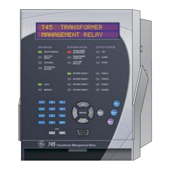
- Page 1 Title Page GE Industrial Systems Transformer Management Relay INSTRUCTION MANUAL Firmware Revision: 4.00 Manual P/N: 1601-0161-A1 Manual Order Code: GEK-106635 Copyright © 2004 GE Multilin 745 STATUS SYSTEM STATUS CONDITIONS TRANSFORMER IN SERVICE TRIP DE-ENERGIZED TRANSFORMER SELF-TEST ALARM OVERLOAD ERROR...
-
Page 3: Table Of Contents
Inputs ..............................2-4 Protection Elements..........................2-5 Outputs ..............................2-6 Miscellaneous ............................. 2-7 INSTALLATION Drawout Case Case Description ..........................3-1 Panel Cutout ............................3-1 Case Mounting ............................ 3-2 Unit Withdrawal and Insertion......................3-3 Typical Wiring Description ............................3-5 GE Multilin http://www.GEindustrial.com/multilin... - Page 4 Triggered Events ..........................4-23 Waveform Capture (Trace Memory)....................4-23 Trending (Data Logger) ........................4-25 Event Recorder ..........................4-27 Modbus User Map..........................4-28 Viewing Actual Values ........................4-29 Using enerVista Viewpoint with the 745 Plug and Play Example ........................4-31 SETPOINTS Overview Setpoint Message Map ........................5-1 GE Multilin http://www.GEindustrial.com/multilin...
- Page 5 Current Demand..........................5-83 Transformer Overload ........................5-84 Tap Changer Failure ......................... 5-85 S5 Outputs Description ............................5-86 Introduction to FlexLogic™ ......................5-86 FlexLogic™ Rules..........................5-87 Output Relays............................ 5-88 Trace Memory ........................... 5-90 Virtual Outputs ..........................5-91 Timers ..............................5-91 GE Multilin http://www.GEindustrial.com/multilin...
- Page 6 Flash Messages ..........................6-21 COMMISSIONING General Introduction............................7-1 Testing Philosophy..........................7-1 Safety Precautions..........................7-2 Conventions ............................7-2 Test Equipment............................7-2 Preliminary Work Description ............................7-4 Dielectric Strength Testing .........................7-4 Logic Inputs and Output Relays Logic Inputs............................7-5 Output Relays ............................7-6 Metering Description ............................7-6 Current Inputs ............................7-6 GE Multilin http://www.GEindustrial.com/multilin...
- Page 7 Transformer Overload ........................7-40 Placing the Relay Into Service Precautions............................7-40 Procedure ............................7-40 APPENDIX Change Notes Revision History ..........................8-1 Changes to the 745 Manual ....................... 8-1 EU Declaration of Conformity GE Multilin Warranty Warranty Statement ........................... 8-3 INDEX GE Multilin http://www.GEindustrial.com/multilin...
- Page 8 Table of Contents Generator Management Relay GE Multilin viii http://www.GEindustrial.com/multilin...
-
Page 9: Getting Started
– mounting screws – registration card (attached as the last page of the manual) • Fill out the registration form and mail it back to GE Multilin (include the serial number located on the rear nameplate). • For product information, instruction manual updates, and the latest software updates, please visit the GE Multilin website at http://www.GEindustrial.com/... -
Page 10: Manual Organization
MESSAGE # or ENTER key to display the header for the first actual values page. The actual values pages are numbered, have an ‘A’ prefix for easy identification and have a name, which gives a general idea of the GE Multilin 1–2 http://www.GEindustrial.com/multilin... - Page 11 MESSAGE # or ENTER key. Pressing MESSAGE # or ENTER while at the Zero-Sequence Current Metering sub-page heading displays the following: W1 NEG SEQ CURRENT: 0 A at 0° Lag GE Multilin 1–3 http://www.GEindustrial.com/multilin...
-
Page 12: Panel Keying Example
Pressing the $ MESSAGE key reverses the process described above and returns the display to the previous level. ! AGING FACTOR LIMIT Press the $ MESSAGE key twice to return to the page header. S4 ELEMENTS ! SETPOINTS S4 ELEMENTS GE Multilin 1–4 http://www.GEindustrial.com/multilin... -
Page 13: Changing Setpoints
69.3, since the step value for this setpoint is 0.1. NEW SETPOINT HAS BEEN STORED Enumeration Setpoints Enumeration setpoints have data values which are part of a set, whose members are explicitly defined by a name. A set is comprised of two or more members. GE Multilin 1–5 http://www.GEindustrial.com/multilin... -
Page 14: Text Setpoints
If a character is entered incorrectly, press the decimal key repeatedly until the cursor returns to the position of the error and re-enter the character as required. Once complete, press ENTER to remove the solid cursor and save the result. OUTPUT 3 NAME: INST DIFF TRIP GE Multilin 1–6 http://www.GEindustrial.com/multilin... -
Page 15: Security
Press the ENTER key to store the new passcode and a confirmation message appears. As a safety measure, the relay requires you to enter a new passcode twice. This ensures the passcode has been entered correctly. PLEASE RE-ENTER NEW PASSCODE: GE Multilin 1–7 http://www.GEindustrial.com/multilin... - Page 16 PLEASE ENTER CURRENT PASSCODE: Press the ENTER key and this message will flash on the display. It indicates that passcode security is now enabled. SETPOINT ACCESS IS NOW RESTRICTED After a few seconds, the original display returns. GE Multilin 1–8 http://www.GEindustrial.com/multilin...
-
Page 17: Overview
745’s simulation buffer for “playback”. A Waveform Capture function that records waveform data for fault, inrush, or alarm conditions is also provided. The Auto-Configuration function eliminates the need for any special CT connections by having all CTs connected in wye. GE Multilin 2–1 http://www.GEindustrial.com/multilin... -
Page 18: Protection Features
251N Neutral (3I ) Time Overcurrent 387TG Ground Differential (Restricted Ground Fault) 251G Ground Time Overcurrent 3THD Total Harmonic Distortion Level 287TG Ground Differential (Restricted Ground Current Demand Fault) 2THD Total Harmonic Distortion Level Current Demand GE Multilin 2–2 http://www.GEindustrial.com/multilin... -
Page 19: Order Codes
40 to 60 V DC; 20 to 48 V AC at 48 to 62 Hz power 90 to 300 V DC; 70 to 265 V AC at 48 to 62 Hz Options Analog Inputs/Outputs Loss of Life Restricted Ground Fault Display Basic display Enhanced display, larger LCD GE Multilin 2–3 http://www.GEindustrial.com/multilin... -
Page 20: Specifications
≥ 4 × CT: ±0.5% of 46 × CT (±0.2 × CT) DC shift: Overload Withstand: 1 second at 80 times Input impedance: 70 to 100 kΩ rated current; 2 seconds at 40 times rated current; continuous at 3 times rated current GE Multilin 2–4 http://www.GEindustrial.com/multilin... -
Page 21: Protection Elements
0.1 s; 0.05 to 100.00 for IEC curves in steps of 0.01 Reset type: Instantaneous or Linear Level accuracy: Per current input Timing accuracy: ±3% of trip time or ±20 ms (whichever is greater) at ≥ 1.03 × pickup GE Multilin 2–5 http://www.GEindustrial.com/multilin... -
Page 22: Outputs
Output range: 0-1 mA, 0-5 mA, 0-10 mA, 0- 20 mA, or 4-20 mA Maximum load: 10 kΩ at 0 to 1 mA 600 Ω at 4 to 20 mA Isolation: Fully isolated Accuracy: ±1% of full scale GE Multilin 2–6 http://www.GEindustrial.com/multilin... -
Page 23: Miscellaneous
Thermal: Operational test at ambient then increasing to 60°C Dielectric Strength: per IEC 255-5 and ANSI/ IEEE C37.90 on CT inputs, VT inputs, Control Power inputs, Switch inputs, and Relay outputs (2 kV for 1 second) GE Multilin 2–7 http://www.GEindustrial.com/multilin... - Page 24 FCC: Part 15; RF Emissions for North America IEC: IEC 1010-1 LVD - CE for Europe ISO: GE Multilin’s Quality Management System is registered to ISO9001:2000 QMI # 005094 UL #A3775 UL listed for the USA and Canada, E83849 It is recommended that all 745 relays be powered up at least once per year to avoid deterioration of electrolytic capacitors in the power supply.
-
Page 25: Installation
Panel cutout dimensions for both conditions are as shown. When planning the location of your panel cutout, ensure provision is made for the front door to swing open without interference to or from adjacent equipment. GE Multilin 3–1 http://www.GEindustrial.com/multilin... -
Page 26: Case Mounting
After bending all tabs, the case will be securely mounted so that its relay can be inserted. The SR unit is now ready for panel wiring. FIGURE 3–4: Case Mounting GE Multilin 3–2 http://www.GEindustrial.com/multilin... -
Page 27: Unit Withdrawal And Insertion
FIGURE 3–5: Press Latch to Disengage Handle Grasp the locking handle in the center and pull firmly, rotating the handle up from the bottom of the unit until movement ceases. FIGURE 3–6: Rotate Handle to Stop Position GE Multilin 3–3 http://www.GEindustrial.com/multilin... - Page 28 If access to the front panel controls must be restricted, a separate seal can be installed on the outside of the cover to prevent it from being opened. FIGURE 3–8: Drawout Unit Seal GE Multilin 3–4 http://www.GEindustrial.com/multilin...
-
Page 29: Typical Wiring
As such, it is not possible to present connections for all possible schemes. The information in this section covers the important aspects of interconnections, in the general areas of instrument transformer inputs, other inputs, outputs, communications, and grounding. Rear Terminal Layout FIGURE 3–9: Rear Terminal Layout GE Multilin 3–5 http://www.GEindustrial.com/multilin... - Page 30 Phase C: Winding 3 CT ! Setpoint Access (–) Ground: Winding 1/2 CT ! Logic Power Out (+) Control Power (–) Logic Power Out (–) Control Power (+) ! indicates high side of CT and VT terminals GE Multilin 3–6 http://www.GEindustrial.com/multilin...
-
Page 31: Wiring Diagrams
MW. This can be corrected by reversing the voltage input into C11 and C12. FIGURE 3–10: Typical Wiring for Two Winding Transformer GE Multilin 3–7 http://www.GEindustrial.com/multilin... - Page 32 Typical Wiring Transformer Management Relay FIGURE 3–11: Typical Wiring for Three Winding Transformer GE Multilin 3–8 http://www.GEindustrial.com/multilin...
-
Page 33: Phase Sequence And Transformer Polarity
Twisted pair cabling on the zero-sequence CT is recommended. IMPORTANT: The relay will correctly measure up to 46 times the current input nominal rating. Time overcurrent curves become horizontal lines for currents above the 46 × CT rating. NOTE GE Multilin 3–9 http://www.GEindustrial.com/multilin... -
Page 34: Ac Voltage Input
745 RELAY +32 V DC +32 V DC Logic Input 1 Logic Input 1 32 V DC 32 V DC 30 to 300 V DC DC Negative DC Negative LOGICIN.CDR FIGURE 3–13: Dry and Wet Contact Connections GE Multilin 3–10 http://www.GEindustrial.com/multilin... -
Page 35: Control Power
RTD devices. This connection may be made using two or three wires to the RTD. Terminal B10 is connected internally to a 5 mA current source for energizing the RTD. Terminal B11 is connected internally to a 5 mA GE Multilin 3–11 http://www.GEindustrial.com/multilin... -
Page 36: Output Relays
0.001 A = 5 KΩ. Similarly, for a 0 to 5 mA channel this resistor would be 1 KΩ; for a 0 to 10 mA channel, this resistor would be 500 Ω; and for a 4 to 20 mA channel this resistor would be 250 Ω. FIGURE 3–15: Analog Output Connection GE Multilin 3–12 http://www.GEindustrial.com/multilin... -
Page 37: Rs485 / Rs422 Communications
An isolated power supply with an optocoupled data interface also acts to reduce noise coupling. To ensure maximum reliability, all equipment should have similar transient protection devices installed. FIGURE 3–16: RS485 Wiring GE Multilin 3–13 http://www.GEindustrial.com/multilin... -
Page 38: Rs232 Front Panel Program Port
PC. This port uses the same Modbus protocol as the two rear ports. The enerVista Program Port 745 Setup software required to use this interface is included with the relay. Cabling for the RS232 port is shown below for both 9 pin and 25 pin connectors. FIGURE 3–18: RS232 Wiring GE Multilin 3–14 http://www.GEindustrial.com/multilin... -
Page 39: Irig-B
No special ventilation requirements need to be observed during the installation of the unit. The unit does not have to be cleaned. NOTE Hazard may result if the product is not used for its intended purpose. WARNING GE Multilin 3–15 http://www.GEindustrial.com/multilin... - Page 40 Typical Wiring Transformer Management Relay GE Multilin 3–16 http://www.GEindustrial.com/multilin...
-
Page 41: Interfaces
The RS232 program port is also provided for connection with a computer running the enerVista 745 Setup software. DISPLAY STATUS INDICATORS KEYPAD RS232 INTERFACE FIGURE 4–1: 745 Front Panel View GE Multilin 4–1 http://www.GEindustrial.com/multilin... -
Page 42: Leds
RESET key is operational. • MESSAGE: The Message LED indicator is on when any element has picked up, operated, or is now in a latched state waiting to be reset. With this indicator on, GE Multilin 4–2 http://www.GEindustrial.com/multilin... -
Page 43: Program Port
There are three main menus labeled Setpoints, Actual Values, and Target Messages. Pressing the MENU key followed by the MESSAGE key scrolls through the three main menu headers, which appear in sequence as follows: SETPOINTS ACTUAL VALUES TARGET MESSAGES GE Multilin 4–3 http://www.GEindustrial.com/multilin... - Page 44 “Tx. Monitor” are entered. Note that a space is selected like a character. If a character is entered incorrectly, press the decimal [.] key repeatedly until the cursor returns GE Multilin 4–4 http://www.GEindustrial.com/multilin...
-
Page 45: Setpoint Entry
& required message is reached. The end of a page is indicated by the message . The beginning of a page is indicated by the message END OF PAGE TOP OF PAGE GE Multilin 4–5 http://www.GEindustrial.com/multilin... -
Page 46: Diagnostic Messages
S1 745 SETUP !" PREFERENCES !" DEFAULT MESSAGE . The factory default flash message time is 4 seconds. For additional CYCLE TIME information and a complete list of flash messages, refer to Flash Messages on page 6–21. GE Multilin 4–6 http://www.GEindustrial.com/multilin... -
Page 47: Enervista Software Interface
RS232, RS485, and Ethernet (requires the MultiNET adapter) communications. The following figures below illustrate typical connections for RS232 and RS485 communications. For additional details on Ethernet communications, please see the MultiNET manual (GE Publication number GEK-106498). FIGURE 4–2: Communications using The Front RS232 Port GE Multilin 4–7... - Page 48 PCTEL 2304WT V.92 MDC internal modem After ensuring these minimum requirements, use the following procedure to install the enerVista 745 Setup software from the enclosed GE enerVista CD. Insert the GE enerVista CD into your CD-ROM drive. Click the Install Now button and follow the installation instructions to install the no-charge enerVista software on the local PC.
- Page 49 Select the “Web” option to ensure the most recent software release, or select “CD” if you do not have a web connection, then click the Add Now button to list software items for the 745. GE Multilin 4–9 http://www.GEindustrial.com/multilin...
- Page 50 745 Setup software to the Windows start menu. Click Finish to end the installation. The 745 device will be added to the list of installed IEDs in the enerVista Launchpad window, as shown below. GE Multilin 4–10 http://www.GEindustrial.com/multilin...
-
Page 51: Connecting Enervista 745 Setup To The Relay
(for RS485 communications). This example demonstrates an RS232 connection. For RS485 communications, the GE Multilin F485 converter will be required. Refer to the F485 manual for additional details. To configure the relay for Ethernet communications, see Configuring Ethernet Communications on page 4–13. - Page 52 Site List window. The properties of this new site cannot be changed. The 745 Site Device has now been configured via the Quick Connect feature for serial communications. Proceed to Connecting to the Relay on page 4–14 to begin communications. GE Multilin 4–12 http://www.GEindustrial.com/multilin...
- Page 53 MultiNET to work with the 745. Install and start the latest version of the enerVista 745 Setup software (available from the GE enerVista CD). See the previous section for the installation procedure. Click on the Device Setup button to open the Device Setup window and click the Add Site button to define a new site.
-
Page 54: Connecting To The Relay
Actual values windows are also available for display. These windows can be locked, arranged, and resized at will. Refer to the enerVista 745 Setup Help File for additional information about the using the software. NOTE GE Multilin 4–14 http://www.GEindustrial.com/multilin... -
Page 55: Working With Setpoints And Setpoint Files
Click Accept to exit from the keypad and keep the new value. Click on Cancel to exit from the keypad and retain the old value. GE Multilin 4–15 http://www.GEindustrial.com/multilin... -
Page 56: File Support
Factory default values are supplied and can be restored after any changes. The enerVista 745 Setup display relay setpoints with the same hierarchy as the front panel display. For specific details on setpoints, refer to Chapter 5. GE Multilin 4–16 http://www.GEindustrial.com/multilin... - Page 57 The Open dialog box will appear, prompting for a previously saved setpoint file. ® As for any other Windows application, browse for the file to add then click Open. The new file and complete path will be added to the file list. GE Multilin 4–17 http://www.GEindustrial.com/multilin...
- Page 58 It is often necessary to upgrade the revision code for a previously saved setpoint file after the 745 firmware has been upgraded (for example, this is required for firmware upgrades). This is illustrated in the following procedure. Establish communications with the 745 relay. GE Multilin 4–18 http://www.GEindustrial.com/multilin...
- Page 59 From the main window, select the File > Print Settings menu item. The Print/Export Options dialog box will appear. Select Settings in the upper section and select either Include All Features (for a complete list) or Include GE Multilin 4–19 http://www.GEindustrial.com/multilin...
- Page 60 Right-click on the selected file and select the Write Settings to Device item. If the relay is currently in-service, the enerVista 745 Setup software will generate a warning message reminding the user to remove the relay from service before attempting to load setpoints. GE Multilin 4–20 http://www.GEindustrial.com/multilin...
-
Page 61: Upgrading Relay Firmware
To upgrade the 745 firmware, follow the procedures listed in this section. Upon successful completion of this procedure, the 745 will have new firmware installed with the original setpoints. The latest firmware files are available from the GE Multilin website at http:// www.GEindustrial.com/multilin. - Page 62 745. The firmware filename has the following format: 33 G 400 A0 .000 Modification Number (000 = none) GE Multilin use only Firmware Revision Required 745 hardware revision Product code (33 = 745 Transformer Mgt. Relay) FIGURE 4–5: Firmware File Format...
-
Page 63: Advanced Enervista 745 Setup Features
Click on the Save to File button to save the selected waveform to the local PC. A new window will appear requesting for file name and path. GE Multilin 4–23 http://www.GEindustrial.com/multilin... - Page 64 The event record will provide additional information on the cause and the system conditions at the time of the event. Additional information on how to download and save events is shown in Event Recorder on page 4–27. GE Multilin 4–24 http://www.GEindustrial.com/multilin...
-
Page 65: Trending (Data Logger)
Positive-, negative-, and zero-sequence currents for Windings 1, 2, and 3 , and I differential and restraint currents System frequency Frequency decay rate • Harmonics: Total harmonic distortion (THD) Harmonic derating factor • Temperature: Ambient Temperature Hottest-Spot Winding Temperature RTDs 1 through 12 GE Multilin 4–25 http://www.GEindustrial.com/multilin... - Page 66 The minimum number of samples is 1000. At a sampling rate of 5 seconds (or 1 sample every 5 seconds), the file will contain data collected during the past 5000 seconds. The enerVista 745 Setup software will automatically esti- mate the size of the trending file. GE Multilin 4–26 http://www.GEindustrial.com/multilin...
-
Page 67: Event Recorder
Use the following procedure to view the event recorder with enerVista 745 Setup: With enerVista 745 Setup running and communications established, select the Actual > Event Recorder item from the main menu. This displays the Event GE Multilin 4–27 http://www.GEindustrial.com/multilin... -
Page 68: Modbus User Map
Modbus User Map The enerVista 745 Setup software provides a means to program the 745 User Map (Modbus addresses 0180h to 01F7h). Refer to GE Publication GEK-106636: 745 Communications Guide for additional information on the User Map. Select a connected device in enerVista 745 Setup. -
Page 69: Viewing Actual Values
(THD), as well as harmonic derating factor. – Phase-to-neutral voltage metering, volts-per-hertz, and system frequency. – Tap changer position. – Current demand for each winding including peak values. – Real, reactive, and apparent power for each winding, along with the power factor. GE Multilin 4–29 http://www.GEindustrial.com/multilin... - Page 70 The windows can be re-arranged to maximize data viewing as shown in the following figure (showing actual demand, harmonic contents, and current values tiled in the same window): FIGURE 4–9: Actual Values Display GE Multilin 4–30 http://www.GEindustrial.com/multilin...
-
Page 71: Using Enervista Viewpoint With The 745
Viewpoint. Information on license pricing can be found at http://www.enerVista.com. Install the enerVista Viewpoint software from the GE enerVista CD. Ensure that the 745 device has been properly configured for either serial or Ethernet communications (see previous sections for details). - Page 72 Plug and Play IED dashboard. An icon for the 745 will be shown. FIGURE 4–12: ‘Plug and Play’ Dashboard 12. Click the Dashboard button below the 745 icon to view the device information. We have now successfully accessed our 745 through enerVista Viewpoint. GE Multilin 4–32 http://www.GEindustrial.com/multilin...
- Page 73 Using enerVista Viewpoint with the 745 Transformer Management Relay FIGURE 4–13: enerVista Plug and Play Screens (Example) For additional information on enerVista viewpoint, please visit the enerVista website at http://www.enerVista.com. GE Multilin 4–33 http://www.GEindustrial.com/multilin...
- Page 74 Using enerVista Viewpoint with the 745 Transformer Management Relay GE Multilin 4–34 http://www.GEindustrial.com/multilin...
-
Page 75: Setpoints
! INSTALLATION MESSAGE See page 5–29. ! UPGRADE MESSAGE See page 5–29. OPTIONS ! END OF PAGE S1 MESSAGE ! SETPOINTS ! TRANSFORMER See page 5–30. S2 SYSTEM SETUP ! WINDING 1 MESSAGE See page 5–32. GE Multilin 5–1 http://www.GEindustrial.com/multilin... - Page 76 ! PHASE OC MESSAGE See page 5–49. ! NEUTRAL OC MESSAGE See page 5–56. ! GROUND OC MESSAGE See page 5–59. ! RESTRICTED MESSAGE See page 5–61. GROUND ! NEG SEQ OC MESSAGE See page 5–64. GE Multilin 5–2 http://www.GEindustrial.com/multilin...
- Page 77 ! SETPOINTS ! OUTPUT RELAYS See page 5–92. S6 TESTING ! ANALOG OUTPUTS MESSAGE See page 5–92. ! SIMULATION MESSAGE See page 5–93. ! FACTORY MESSAGE See page 5–93. SERVICE ! END OF PAGE S6 MESSAGE GE Multilin 5–3 http://www.GEindustrial.com/multilin...
-
Page 78: Setpoint Entry
Passcode protection may also be enabled. When enabled, the 745 requests a numeric passcode before any setpoint can be entered. As an additional safety measure, a minor self-test error is generated when the passcode is entered incorrectly three times in a row. GE Multilin 5–4 http://www.GEindustrial.com/multilin... -
Page 79: Auto-Configuration
WINDING 1 WINDING 1 NOM Φ-Φ VOLTAGE : “100 MVA” S2 SYSTEM SETUP WINDING 1 WINDING 1 RATED LOAD !" !" : “500:1 A” S2 SYSTEM SETUP !" WINDING 1 !" WINDING 1 PHASE CT PRIMARY GE Multilin 5–5 http://www.GEindustrial.com/multilin... - Page 80 TAP 2 TAP 6 WIPER AT TAP 5 TAP 1 TAP 7 ZERO TAP 8 POSITION TAP 9 etc. ZERO POSITION WIPER TERMINAL TERMINAL (to TAP POSITION -) (to TAP POSITION +) FIGURE 5–1: Tap Position Input GE Multilin 5–6 http://www.GEindustrial.com/multilin...
- Page 81 The example below shows why this happens, using a transformer described in IEC nomenclature as “Yd1” or in GE Multilin nomenclature as “Y/d30.” FIGURE 5–2: Example Transformer The above figure shows the physical connections within the transformer that produce a phase angle in the delta winding that lags the respective wye winding by 30°.
- Page 82 Note that the Delta winding currents leads the Wye winding currents by 30°, (which is a type Yd11 in IEC nomenclature and a type Y/d330 in GE Multilin nomenclature) which is in disagreement with the transformer nameplate. This is because the physical connections and hence the equations used to calculate current for the delta winding have not changed.
-
Page 83: Phase Angle Correction
INP UT OUTP UT P HAS OR phase shift S HIFT P HAS ORS P HAS ORS TRANS FORMATION 30° lag a =(A – C) / b =(B – A) / c =(C – B) / GE Multilin 5–9 http://www.GEindustrial.com/multilin... -
Page 84: Zero-Sequence Component Removal
The 745 removes zero-sequence current from all Wye/Wye and Wye/Wye/Wye transformer windings to prevent possible relay malopera- tions resulting from these two conditions. GE Multilin 5–10 http://www.GEindustrial.com/multilin... -
Page 85: Transformer Types
0° 240° lag 150° lag D/d300° DELTA 300° Y/d210° 210° (gnd 1/2) DELTA 0° 300° lag DELTA 0° 210° lag D/y30° DELTA 0° Y/d330° 330° (gnd 1/2) 330° (gnd 1/2) 30° lag DELTA 0° 330° lag GE Multilin 5–11 http://www.GEindustrial.com/multilin... - Page 86 210° (gnd 1/2) ZIG-ZAG 0° (gnd 1/2) 300° lag ZIG-ZAG 0° (gnd 2/3) 0° 210° lag External (gnd 1/2) Correction Y/z330° 330° (gnd 1/2) 0° (gnd 2/3) 0° ZIG-ZAG 0° (gnd 2/3) 0° 330° lag 0° GE Multilin 5–12 http://www.GEindustrial.com/multilin...
- Page 87 180° lag DELTA 0° DELTA 0° 210° lag 210° lag Y/y0°/ 330° Y/y180°/ 330° d330° (gnd 1/2) d330° (gnd 1/2) 330° 150° (gnd 2/3) (gnd 2/3) 0° 180° lag DELTA 0° DELTA 0° 330° lag 330° lag GE Multilin 5–13 http://www.GEindustrial.com/multilin...
- Page 88 150° lag DELTA 0° 150° 30° lag (gnd 2/3) 0° Y/d30°/ 30° Y/d150°/ 150° d150° (gnd 1/2) y180° (gnd 1/2) DELTA 0° DELTA 0° 30° lag 150° lag DELTA 240° 330° 150° lag (gnd 2/3) 180° lag GE Multilin 5–14 http://www.GEindustrial.com/multilin...
- Page 89 150° lag DELTA 180° DELTA 300° 30° lag 210° lag Y/d210°/ 210° Y/d150°/ 150° d150° (gnd 1/2) d330° (gnd 1/2) DELTA 0° DELTA 0° 210° lag 150° lag DELTA 60° DELTA 180° 150° lag 330° lag GE Multilin 5–15 http://www.GEindustrial.com/multilin...
- Page 90 330° lag 330° DELTA 120° (gnd 2/3) 210° lag 0° Y/d330°/ 330° Y/d330°/ 330° y180° (gnd 1/2) d330° (gnd 1/2) DELTA 0° DELTA 0° 330° lag 330° lag 150° DELTA 0° (gnd 2/3) 330° lag 180° lag GE Multilin 5–16 http://www.GEindustrial.com/multilin...
- Page 91 0° DELTA 0° 0° DELTA 0° 180° lag 150° (gnd 2/3) 210° lag D/d0°/ DELTA 240° d240° D/d0°/ DELTA 0° y330° DELTA 240° 0° DELTA 0° 0° DELTA 0° 240° lag 30° (gnd 2/3) 330° lag GE Multilin 5–17 http://www.GEindustrial.com/multilin...
- Page 92 330° 210° (gnd 2/3) 30° lag (gnd 2/3) 150° lag D/d60°/ DELTA 0° D/d120°/ DELTA 0° y210° y330° DELTA 300° 60° lag DELTA 240° 120° lag 150° (gnd 2/3) 30° 210° lag (gnd 2/3) 330° lag GE Multilin 5–18 http://www.GEindustrial.com/multilin...
- Page 93 180° lag DELTA 0° 240° lag DELTA 0° 300° lag D/d240°/ DELTA 0° y30° D/d180°/ DELTA 0° y150° DELTA 120° 240° lag DELTA 180° 180° lag 330° (gnd 2/3) 30° lag 210° (gnd 2/3) 150° lag GE Multilin 5–19 http://www.GEindustrial.com/multilin...
- Page 94 D/y150°/ DELTA 0° d120° 330° (gnd 1/2) 30° lag 210° (gnd 1/2) 150° lag DELTA 300° 60° lag DELTA 240° 120° lag D/y30°/ DELTA 0° d240° 330° (gnd 1/2) 30° lag DELTA 120° 240° lag GE Multilin 5–20 http://www.GEindustrial.com/multilin...
- Page 95 150° 210° (gnd 1/2) (gnd 1/2) 210° lag 150° lag 330° 30° (gnd 2/3) (gnd 2/3) 30° lag 330° lag D/y210°/ DELTA 0° y210° 150° (gnd 1/2) 210° lag 150° (gnd 2/3) 210° lag GE Multilin 5–21 http://www.GEindustrial.com/multilin...
- Page 96 0° DELTA 180° 0° 180° lag (gnd 2/3) 0° D/y330°/ DELTA 0° d300° 30° (gnd 1/2) 330° lag DELTA 60° 300° lag D/y330°/ DELTA 0° y150° 30° (gnd 1/2) 330° lag 210° (gnd 2/3) 150° lag GE Multilin 5–22 http://www.GEindustrial.com/multilin...
-
Page 97: Phase Shifts
= (A – C) / c = (B – A) / 300° a = –B b = –C c = –A 330° a = (A – B) / b = (B – C) / c = (C – A) / GE Multilin 5–23 http://www.GEindustrial.com/multilin... -
Page 98: S1 745 Setup
The time these messages remain on the display, overriding the normal messages, can be changed to accommodate different user reading rates. GE Multilin 5–24 http://www.GEindustrial.com/multilin... -
Page 99: Communications
The parity of the transmitted signal must match the parity displayed in this setpoint. • COM1 HARDWARE: If the two-wire RS485 hardware configuration is required for the COM1 serial communication port, select RS485. This setpoint cannot be GE Multilin 5–25 http://www.GEindustrial.com/multilin... - Page 100 DNP PORT: Selects the communication port for DNP communications. • DNP POINT MAPPING: When enabled, the 120 User Map Values are included in the DNP Object 30 point list. For additional information, refer to GE publication GEK-106636: 745 Communications Guide. •...
-
Page 101: Resetting
S1 745 SETUP !" DEFAULT MESSAGES Range: cannot be edited ! DEFAULT 1 MESSAGES SELECTED MESSAGES 29 REMAIN UNASSIGNED ENTER ENTER Range: Press [.] at any 745 Transformer MESSAGE message to select as a default Management Relay message. GE Multilin 5–27 http://www.GEindustrial.com/multilin... -
Page 102: Scratchpad
5. The text may be changed from Text 1 one character at a time, using the VALUE keys. Press the ENTER key to store the edit and advance to the next character position. This message may then be stored as a default message. GE Multilin 5–28 http://www.GEindustrial.com/multilin... -
Page 103: Installation
Yes and press ENTER to prompt the 745 to upgrade its options. A flash message appears indicating the results of the upgrade. A successful upgrade may be verified by examining the installed options display under A4 PRODUCT INFO !" REVISION CODES !" INSTALLED OPTIONS GE Multilin 5–29 http://www.GEindustrial.com/multilin... -
Page 104: S2 System Setup
• PHASE SEQUENCE: Enter the phase sequence of the power system. Systems with an ACB phase sequence require special considerations. See Phase Shifts on Three-Phase Transformers on page 5–7 for details. GE Multilin 5–30 http://www.GEindustrial.com/multilin... - Page 105 XFMR THRML CAPACITY: Required for insulation aging calculations. Obtain from transformer manufacturer • WINDING TIME CONST: Required for insulation aging calculations • ACCUMULATED LOSS LIFE: Required insulation aging calculations. Set equal to the estimated accumulated loss of life. GE Multilin 5–31 http://www.GEindustrial.com/multilin...
-
Page 106: Windings 1 To 3
(that is, the sum of the resistance of each of the three phases for the winding). This value is normally only available from the transformer manufacturer’s test report, and is used in the 745 for calculation of harmonic derating factor. GE Multilin 5–32 http://www.GEindustrial.com/multilin... -
Page 107: Onload Tap Changer
The 745 calculates the individual harmonics in each of the phase current inputs up to the 21 harmonic. With this information, it calculates an estimate of the effect of non-sinusoidal load currents on the transformer rated full load current. These calculations are based on ANSI/IEEE Standard C57.110-1986, and require GE Multilin 5–33 http://www.GEindustrial.com/multilin... -
Page 108: Flexcurves
VOLTAGE INPUT PARAMETER: Enter the winding and phase of the voltage connected to the voltage input. • NOMINAL VT SECONDARY VOLTAGE: Enter the nominal secondary voltage (in volts) of the voltage transformer. • VT RATIO: Enter the ratio of the voltage transformer. GE Multilin 5–34 http://www.GEindustrial.com/multilin... -
Page 109: Ambient Temperature
AVERAGE AMBIENT TEMPERATURE (BY MONTH): This message is displayed only when the is set for “By Monthly Average”. AMBIENT RTD TYPE Ambient temperature is used in the calculation of Insulation Aging and must be enabled for the function to operate. GE Multilin 5–35 http://www.GEindustrial.com/multilin... -
Page 110: Analog Input
It calculates the ‘thermal demand equivalent’ as follows: – d t ( ) D 1 e (EQ 5.3) – where d = demand after applying input for time t (in minutes) D = input quantity (constant) --------------------------------------------------------------------------------------- - Thermal 90% Response Time GE Multilin 5–36 http://www.GEindustrial.com/multilin... - Page 111 0 to 10 mA. Each channel can be programmed to monitor any measured parameter. This sub-section is only displayed with the option installed. • ANALOG OUTPUT 1(7) FUNCTION: This message enables or disables the Analog Output 1(7) feature. When disabled, 0 mA will appear at the corresponding terminal. GE Multilin 5–37 http://www.GEindustrial.com/multilin...
-
Page 112: S3 Logic Inputs
! LOGIC INPUT 1 INPUT 1 FUNCTION: Disabled Range: None, Latched, Self-Reset INPUT 1 TARGET: MESSAGE Self-Reset Range: 18 alphanumeric characters INPUT 1 NAME: MESSAGE Logic Input 1 Range: Open, Closed INPUT 1 ASSERTED MESSAGE STATE: Closed GE Multilin 5–38 http://www.GEindustrial.com/multilin... -
Page 113: Virtual Inputs 1 To 16
FUNCTION: Enabled Select “Enabled” to enable the element. For critical protection elements, this setpoint is normally “Enabled” except for test purposes. For elements which are not to be used, this setpoint should be set to “Disabled”. GE Multilin 5–39 http://www.GEindustrial.com/multilin... - Page 114 = DELAY. LED INDICATORS • Shown as the following schematic symbol: ⊗. • The exact wording of the front panel label identifies the indicator. LOGIC • Described using basic AND gates and OR gates GE Multilin 5–40 http://www.GEindustrial.com/multilin...
-
Page 115: Setpoint Group
, which allows changing the characteristics of the inhibit scheme ENERGIZATION INHIBIT during energization to improve reliability; and , which implements 5TH HARM INHIBIT an inhibit scheme based on 5th harmonic only, allowing inhibiting the percent differential during intentional overexcitation of the system. GE Multilin 5–41 http://www.GEindustrial.com/multilin... - Page 116 The basic percent differential operating principle for three-winding transformers is illustrated by the following equations: max I restraint differential (EQ 5.4) %slope × 100% ---- - The basic percent differential operating principle for two-winding transformers is illustrated by the following equations: GE Multilin 5–42 http://www.GEindustrial.com/multilin...
- Page 117 , the differential current is not always greater restraint' than 100% of the restraint current. Because of this enhancement, the PERCENT setting may cause slow operation (in rare cases no operation) in DIFFERENTIAL SLOPE 2 NOTE the following situations: GE Multilin 5–43 http://www.GEindustrial.com/multilin...
- Page 118 RMS sum of the 2 and 5 harmonic components. For most transformers, the 2 harmonic current alone will exceed 20% during energization and the “2nd” value is sufficient to inhibit the differential element for inrush current. GE Multilin 5–44 http://www.GEindustrial.com/multilin...
- Page 119 0.01. Seen only if Voltage VOLTAGE: 0.85 x VT Sensing is enabled. Range: Logic Input 1 to 16, Disabled BREAKERS ARE OPEN MESSAGE SIGNAL: Disabled Range: Logic Input 1 to 16, Disabled PARALL XFMR BRKR CLS MESSAGE SIGNAL: Disabled GE Multilin 5–45 http://www.GEindustrial.com/multilin...
- Page 120 This setpoint is displayed only if S2 SYSTEM SETUP !" is “Enabled”. VOLTAGE INPUT VOLTAGE SENSING • MINIMUM ENERGIZATION VOLTAGE: Enter the voltage level below which the transformer is considered de-energized (when ENERGIZATION SENSING BY GE Multilin 5–46 http://www.GEindustrial.com/multilin...
- Page 121 745 the onset of sympathetic inrush. The selected logic input should be connected to the close command going to the parallel transformer switching device. FIGURE 5–10: Energization Inhibit Scheme Logic FIGURE 5–11: Energization Sensing Scheme Logic GE Multilin 5–47 http://www.GEindustrial.com/multilin...
-
Page 122: Instantaneous Differential
MESSAGE 16, Output Rly 2 to 8, SelfTest BLOCK: Disabled Rly, Vir Outpt 1 to 5, Disabled This section contains the settings to configure the (unrestrained) instantaneous differential element, for protection under high magnitude internal faults. GE Multilin 5–48 http://www.GEindustrial.com/multilin... -
Page 123: Phase Overcurrent
! W3 PHASE MESSAGE See page 5–55. INST OC 2 This section contains settings to configure the phase overcurrent elements. Included are phase time overcurrents and two levels of phase instantaneous overcurrent for each phase of each winding. GE Multilin 5–49 http://www.GEindustrial.com/multilin... - Page 124 Time Overcurrent Curves The inverse time overcurrent curves used by the TOC (time overcurrent) elements are the ANSI, IEC, and GE Type IAC curve shapes. This allows for simplified coordination with downstream devices. If however, none of these curve shapes is adequate, FlexCurves™...
- Page 125 1.208 1.126 1.066 1.021 0.986 8.106 4.544 2.866 2.291 1.994 1.812 1.689 1.600 1.532 1.479 10.807 6.059 3.821 3.054 2.659 2.416 2.252 2.133 2.043 1.972 10.0 13.509 7.574 4.776 3.818 3.324 3.020 2.815 2.666 2.554 2.465 GE Multilin 5–51 http://www.GEindustrial.com/multilin...
- Page 126 0.231 0.218 0.207 0.60 1.835 1.067 0.668 0.526 0.451 0.404 0.371 0.346 0.327 0.311 0.80 2.446 1.423 0.890 0.702 0.602 0.538 0.494 0.461 0.435 0.415 1.00 3.058 1.778 1.113 0.877 0.752 0.673 0.618 0.576 0.544 0.518 GE Multilin 5–52 http://www.GEindustrial.com/multilin...
- Page 127 – where: T = trip time (seconds), M = multiplier setpoint, I = input current, = pickup current setpoint, A to E = constants. pickup Table 5–8: GE Type IAC Inverse Curve Constants IAC Curve Shape IAC Extreme Inverse 0.0040 0.6379...
- Page 128 (as per ANSI / IEEE C57.110-1986) and, when this feature is enabled, automatically shifts the phase time overcurrent curve pickup in order to maintain the required protection margin with respect to the transformer thermal damage curve, as illustrated below. GE Multilin 5–54 http://www.GEindustrial.com/multilin...
- Page 129 MESSAGE DELAY: 0 ms Range: Logc Inpt 1 to 16, Virt Inpt 1 to W1 PHASE INST OC 1 MESSAGE 16, Output Rly 2 to 8, SelfTest BLOCK: Disabled Rly, Vir Outpt 1 to 5, Disabled GE Multilin 5–55 http://www.GEindustrial.com/multilin...
-
Page 130: Neutral Overcurrent
In the 745, “neutral” refers to residual current (3I ), calculated internally as the vector sum of the three phases. The relay includes neutral time overcurrent and two levels of neutral instantaneous overcurrent for each winding. GE Multilin 5–56 http://www.GEindustrial.com/multilin... - Page 131 (when the current falls below the reset threshold before tripping) is proportional to ratio of energy accumulated to that required to trip. Select “Instantaneous” reset to coordinate with relays, such as most static units, with instantaneous reset characteristics. FIGURE 5–17: Neutral Time Overcurrent Scheme Logic GE Multilin 5–57 http://www.GEindustrial.com/multilin...
- Page 132 The setpoint messages above and the following logic diagram are identical for the Neutral Instantaneous Overcurrent 2 element. NOTE FIGURE 5–18: Neutral Instantaneous Overcurrent Scheme Logic GE Multilin 5–58 http://www.GEindustrial.com/multilin...
-
Page 133: Ground Overcurrent
Rly, Vir Outpt 1 to 5, Disabled • W1(3) GROUND TIME OC PICKUP: Enter the level of ground current (in units of relay nominal current) above which the Winding 1(3) Ground Time Overcurrent element will pickup and start timing. GE Multilin 5–59 http://www.GEindustrial.com/multilin... - Page 134 The messages above and scheme logic below are identical for Windings 2 and 3 of Ground Instantaneous Overcurrent 1 and all windings on the Ground Instantaneous Overcurrent 2 element. NOTE GE Multilin 5–60 http://www.GEindustrial.com/multilin...
-
Page 135: Restricted Ground
It is intended to provide sensitive ground fault detection for low magnitude fault currents which would not be detected by the percent differential element. 87TG FIGURE 5–21: Restricted Earth Ground Fault Protection GE Multilin 5–61 http://www.GEindustrial.com/multilin... - Page 136 Ifault Ip(x) Ifault(x) x = distance of fault from neutral FIGURE 5–23: Fault Currents vs. Points from Neutral WINDING DIFFERENTIAL ZONE ZONE FIGURE 5–24: RGF and Percent Differential Zones of Protection GE Multilin 5–62 http://www.GEindustrial.com/multilin...
- Page 137 (in units of Phase CT primary associated with the winding, where the RGF is set) for the Winding 1(3) Restricted Ground Fault element. • W1(3) RESTD GND FAULT SLOPE: Enter a slope percentage (of ground differential current to maximum line current). GE Multilin 5–63 http://www.GEindustrial.com/multilin...
-
Page 138: Negative Sequence Overcurrent
! W3 NEG SEQ MESSAGE See page 5–66. INST OC This section contains the settings to configure the negative sequence overcurrent elements. Included are negative sequence time overcurrents for each winding, and negative sequence instantaneous overcurrents for each winding. GE Multilin 5–64 http://www.GEindustrial.com/multilin... - Page 139 (when the current falls below the reset threshold before tripping) is proportional to ratio of “energy” accumulated to that required to trip. Select Instantaneous reset to coordinate with relays, such as most static units, with instantaneous reset characteristics. FIGURE 5–27: Negative Sequence Time Overcurrent Scheme Logic GE Multilin 5–65 http://www.GEindustrial.com/multilin...
-
Page 140: Frequency
If reserve generation is not available in the area, conditions of low system frequency occur GE Multilin 5–66 http://www.GEindustrial.com/multilin... - Page 141 UNDERFREQUENCY 1(2) PICKUP: Enter the frequency (in Hz) below which the Underfrequency 1 element will pickup and start the delay timer. • UNDERFREQUENCY 1(2) DELAY: Enter the time the frequency remains below the pickup level before element operation. GE Multilin 5–67 http://www.GEindustrial.com/multilin...
- Page 142 RATE 1: 0.4 Hz/s Range: 0.1 to 5.0 Hz/s in steps of 0.1 FREQUENCY DECAY MESSAGE RATE 2: 1.0 Hz/s Range: 0.1 to 5.0 Hz/s in steps of 0.1 FREQUENCY DECAY MESSAGE RATE 3: 2.0 Hz/s GE Multilin 5–68 http://www.GEindustrial.com/multilin...
- Page 143 • FREQUENCY DECAY RATE 1(4): Enter the rate of frequency decay beyond which the corresponding element operates. FIGURE 5–30: Frequency Decay Scheme Logic GE Multilin 5–69 http://www.GEindustrial.com/multilin...
- Page 144 OVERFREQUENCY PICKUP: Enter the frequency (in Hz) above which the overfrequency element will pickup and start the delay timer. • OVERFREQUENCY DELAY: Enter the time that the frequency must remain above the pickup level before the element operates. FIGURE 5–31: Overfrequency Scheme Logic GE Multilin 5–70 http://www.GEindustrial.com/multilin...
-
Page 145: Overexcitation
5th harmonic level element will pickup and start the delay timer. • 5TH HARMONIC LEVEL DELAY: Enter the time that the 5th harmonic current must remain above the pickup level before the element operates. GE Multilin 5–71 http://www.GEindustrial.com/multilin... - Page 146 The element will fully reset after the value. The V/Hz function can be used as an VOLTS-PER-HERTZ RESET instantaneous element with no intentional delay, as a definite time element, or as an inverse timed element. GE Multilin 5–72 http://www.GEindustrial.com/multilin...
- Page 147 ------------------ - 1 – Pickup where T = operate time (seconds) D = delay setpoint (seconds) V = fundamental RMS value of voltage (V) F = frequency of voltage signal (Hz) Pickup = volts-per-hertz pickup setpoint (V/Hz) GE Multilin 5–73 http://www.GEindustrial.com/multilin...
- Page 148 F = frequency of voltage signal (Hz) Pickup = volts-per-hertz pickup setpoint (V/Hz) 10000 1000 Time Delay Setting ò 1.00 1.20 1.40 1.60 1.80 2.00 Multiples of Voltz/Hertz Pickup FIGURE 5–35: Volts Per Hertz Curve 3 GE Multilin 5–74 http://www.GEindustrial.com/multilin...
-
Page 149: Harmonics
See page 5–77. DERATING ! W3 HARMONIC MESSAGE See page 5–77. DERATING This section contains the settings to configure the total harmonic distortion monitoring elements. Included are a THD level element for each winding and each phase. GE Multilin 5–75 http://www.GEindustrial.com/multilin... - Page 150 Winding 1(3) Total Harmonic Distortion element level will pickup and start the delay timer. • W1(3) THD LEVEL DELAY: Enter the time that the total harmonic distortion must remain above the pickup level before the element operates. FIGURE 5–37: THD Level Scheme Logic GE Multilin 5–76 http://www.GEindustrial.com/multilin...
- Page 151 Winding 1(3) Harmonic Derating will pickup and start the delay timer. • W1(3) HARMONIC DERATING DELAY: Enter the time that the harmonic derating must remain below the pickup level before the element operates. FIGURE 5–38: Harmonic Derating Scheme Logic GE Multilin 5–77 http://www.GEindustrial.com/multilin...
-
Page 152: Insulation Aging
The preferred approach for ambient temperature is to use an RTD connected to the 745. If this is not feasible, average values for each month of the year can be entered as settings, under S2 SYSTEM SETUP !" AMBIENT TEMPERATURE !" AMBIENT and selecting By Monthly Average. RTD TYPE GE Multilin 5–78 http://www.GEindustrial.com/multilin... - Page 153 • HOTTEST SPOT LIMIT DELAY: Enter a time delay above which the hottest- spot temperature must remain before the element operates. FIGURE 5–39: Hottest-Spot Limit Scheme Logic GE Multilin 5–79 http://www.GEindustrial.com/multilin...
- Page 154 • AGING FACTOR LIMIT DELAY: Enter a time delay above which the Aging Factor must remain before the element operates. FIGURE 5–40: Aging Factor Limit Scheme Logic GE Multilin 5–80 http://www.GEindustrial.com/multilin...
- Page 155 As an example, for a 15-year transformer, the total number of hours would be 13140 10 = 131400. × The actual values are only displayed if the Loss of Life option is installed and the ambient temperature is enabled. NOTE FIGURE 5–41: Loss-of-Life Scheme Logic GE Multilin 5–81 http://www.GEindustrial.com/multilin...
-
Page 156: Analog Input Level
The analog input is configured in and the actual values displayed in SYSTEM SETUP !" ANALOG INPUT A2 METERING !" ANALOG INPUT FIGURE 5–42: Analog Level Scheme Logic GE Multilin 5–82 http://www.GEindustrial.com/multilin... -
Page 157: Current Demand
Rly, Vir Outpt 1 to 5, Disabled This section contains the settings to configure the current demand monitoring elements. Included are a current demand level for each winding and each phase. FIGURE 5–43: Current Demand Scheme Logic GE Multilin 5–83 http://www.GEindustrial.com/multilin... -
Page 158: Transformer Overload
XFMR OVERTEMP ALARM SIGNAL: Select any logic input that, when asserted, indicates the transformer cooling system has failed and an over- temperature condition exists. The logic input should be connected to the transformer winding temperature alarm contacts. FIGURE 5–44: Transformer Overload Scheme Logic GE Multilin 5–84 http://www.GEindustrial.com/multilin... -
Page 159: Tap Changer Failure
FlexLogic™. This approach would be useful if very sensitive settings had been used in the normal in-service Setpoint group for the Harmonic Restrained Differential element, assuming that the tap changer position was used to compensate the input current magnitude. FIGURE 5–45: Tap Changer Failure Scheme Logic GE Multilin 5–85 http://www.GEindustrial.com/multilin... -
Page 160: S5 Outputs
(i.e. evaluation of the FlexLogic™ equation results in a ‘1’) Timers 1 to 10 The timer runs to completion (i.e. the ‘start’ condition is met for the programmed time delay) * refers to any protection or monitoring element in page S4 ELEMENTS GE Multilin 5–86 http://www.GEindustrial.com/multilin... -
Page 161: Flexlogic™ Rules
AND gate are the output of the NOT gate, and Output Relay 2. The input to the NOT gate is Logic Input 2. The inputs to the 2-input XOR gate are Virtual Output 1 and Logic Input 1. For all these gates, the inputs precede the gate itself. GE Multilin 5–87 http://www.GEindustrial.com/multilin... -
Page 162: Output Relays
(Outputs 2 to 8) in which case it turns off when the relay operates. • OUTPUT 1(8) TYPE: Select “Trip” to turn the Trip LED on or “Alarm” to turn the Alarm LED on when this output operates. Otherwise, select “Control”. Note GE Multilin 5–88 http://www.GEindustrial.com/multilin... - Page 163 Any W1 OC OP OR (2 inputs) Xfmr Overload OR (2 inputs) OR (2 inputs) Any W2 OC OP 5th HarmLevel OR (4 inputs) OR (4 inputs) 06 to 20 FIGURE 5–48: Output Relays Scheme Logic GE Multilin 5–89 http://www.GEindustrial.com/multilin...
-
Page 164: Trace Memory
FlexLogic™ equation for trace memory triggering as described in the introduction to FlexLogic™. The Trace Memory default FlexLogic™ is as follows: : Any Element PKP TRACE TRIG FLEXLOGIC 01 : END TRACE TRIG FLEXLOGIC 02 GE Multilin 5–90 http://www.GEindustrial.com/multilin... -
Page 165: Virtual Outputs
In addition, 16 cycles of sampled current/voltage waveform data (in IEEE Comtrade file format) can be loaded and “played back” to test the response of the 745 under any (previously recorded) system disturbance. GE Multilin 5–91 http://www.GEindustrial.com/multilin... -
Page 166: Output Relays
Analog Output 1(7). For example, if the analog output range has been programmed to 4 to 20 mA, entering 100% outputs 20 mA, 0% outputs 4 mA, and 50% outputs 12 mA. This setpoint is only operational if analog output testing is enabled. GE Multilin 5–92 http://www.GEindustrial.com/multilin... -
Page 167: Simulation
S6 TESTING !" SIMULATION FAULT VALUES !" GE Multilin 5–93 http://www.GEindustrial.com/multilin... - Page 168 ANGLE: 0° Range: 0.0 to 40.0 x CT in steps of 0.1 W1 PHASE B CURRENT MESSAGE MAGNITUDE: 1.0 x CT Range: 0 to 359° in steps of 1 W1 PHASE B CURRENT MESSAGE ANGLE: 0° GE Multilin 5–94 http://www.GEindustrial.com/multilin...
- Page 169 Range: 0.0 to 2.0 x VT in steps of 0.1 VOLTAGE INPUT MESSAGE MAGNITUDE: 1.0 x VT Range: 0 to 359° Lag in steps of 1 VOLTAGE INPUT MESSAGE ANGLE: 0° Lag Range: 45.00 to 60.00 Hz in steps of FREQUENCY: MESSAGE 0.01 60.00 Hz GE Multilin 5–95 http://www.GEindustrial.com/multilin...
- Page 170 Range: 0.0 to 2.0 x VT in steps of 0.1 VOLTAGE INPUT MESSAGE MAGNITUDE: 1.0 x VT Range: 0 to 359° Lag in steps of 1 VOLTAGE INPUT MESSAGE ANGLE: 0° Lag Range: 45.00 to 60.00 Hz in steps of FREQUENCY: MESSAGE 0.01 60.00 Hz GE Multilin 5–96 http://www.GEindustrial.com/multilin...
-
Page 171: Factory Service
! FACTORY SERVICE [!] ENTER FACTORY personnel only PASSCODE: This section contains settings intended for factory use only, for calibration, testing, and diagnostics. The messages can only be accessed by entering a factory service passcode in the first message. GE Multilin 5–97 http://www.GEindustrial.com/multilin... - Page 172 S6 Testing Transformer Management Relay GE Multilin 5–98 http://www.GEindustrial.com/multilin...
-
Page 173: Actual Values
MESSAGE See page 6–4. OUTPUTS ! SELF-TEST MESSAGE See page 6–4. ERRORS ! END OF PAGE A1 MESSAGE MESSAGE ! ACTUAL VALUES ! CURRENT See page 6–5. A2 METERING ! HARMONIC MESSAGE See page 6–8. CONTENT GE Multilin 6–1 http://www.GEindustrial.com/multilin... - Page 174 ! END OF PAGE A3 MESSAGE MESSAGE ! ACTUAL VALUES ! TECHNICAL See page 6–16. A4 PRODUCT INFO SUPPORT ! REVISION CODES MESSAGE See page 6–17. ! CALIBRATION MESSAGE See page 6–17. ! END OF PAGE A4 MESSAGE GE Multilin 6–2 http://www.GEindustrial.com/multilin...
- Page 175 PATH: ACTUAL VALUES A1 STATUS VIRTUAL INPUTS !" ! VIRTUAL INPUTS VIRTUAL INPUT 1 STATE: Not Asserted ↓ VIRTUAL INPUT 16 MESSAGE STATE: Not Asserted The states of Virtual Inputs 1 through 16 are displayed here. GE Multilin 6–3 http://www.GEindustrial.com/multilin...
-
Page 176: Output Relays
BAD SETTINGS ERROR: MESSAGE None value displays the source of the error occurring in a FLEXLOGIC EQN ERROR FlexLogic™ equation. The value displays the cause of a bad BAD SETTINGS ERROR setting made while assigning setpoint values. GE Multilin 6–4 http://www.GEindustrial.com/multilin... -
Page 177: A2 Metering
0 A at 0° Lag W1 NEUTRAL CURRENT: MESSAGE 0 A at 0° Lag W1 GROUND CURRENT: MESSAGE 0 A at 0° Lag WINDING 1 LOADING: MESSAGE 0% of rated load W1 AVERAGE PHASE MESSAGE CURRENT: GE Multilin 6–5 http://www.GEindustrial.com/multilin... - Page 178 W2 ZERO SEQ CURRENT: MESSAGE 0 A at 0° Lag W3 ZERO SEQ CURRENT: MESSAGE 0 A at 0° Lag The zero-sequence current magnitudes and phase values for Windings 1, 2, and 3 are shown here. GE Multilin 6–6 http://www.GEindustrial.com/multilin...
- Page 179 W1 GND DIFFERENTIAL DIFFERENTIAL CURRENT: 0.00 x CT W2 GND DIFFERENTIAL MESSAGE CURRENT: 0.00 x CT W3 GND DIFFERENTIAL MESSAGE CURRENT: 0.00 x CT The ground differential current magnitudes for Windings 1 through 3 are shown. GE Multilin 6–7 http://www.GEindustrial.com/multilin...
-
Page 180: Harmonic Content
21 The second harmonic magnitude for each phase current of Windings 1 through 3 are displayed. Values are expressed as a percentage of magnitude of the corresponding fundamental frequency component. GE Multilin 6–8 http://www.GEindustrial.com/multilin... - Page 181 The Harmonic Derating Factor for each of the windings shows the effect of non- sinusoidal load currents on power transformer’s rated full load current. The calculations are based on ANSI/IEEE standard C57.110-1986. The actual values messages display the harmonic derating factor for Windings 1 through 3. GE Multilin 6–9 http://www.GEindustrial.com/multilin...
-
Page 182: Frequency
CURRENT DEMAND METER TYPE the 745 displays the demand over the most recent demand time interval, the maximum demand since the last date that the demand data was reset, and the time and date stamp of this maximum value. GE Multilin 6–10 http://www.GEindustrial.com/multilin... -
Page 183: Ambient Temperature
These messages are repeated for Windings 2 and 3. Ambient Temperature PATH: ACTUAL VALUES A2 METERING !" AMBIENT TEMPERATURE ! AMBIENT AMBIENT TEMPERATURE: TEMPERATURE 0°C Ambient temperature is monitored via an RTD connected to the 745. GE Multilin 6–11 http://www.GEindustrial.com/multilin... -
Page 184: Loss Of Life
! W2 ENERGY MESSAGE See page 6–13. ! W3 ENERGY MESSAGE See page 6–13. The 745 calculates and displays watthours and varhours for source and load currents for all available windings, providing that the voltage sensing is enabled. GE Multilin 6–12 http://www.GEindustrial.com/multilin... -
Page 185: A3 Event Recorder
CLEAR EVENT RECORDER SIGNAL remote clearing of the event recorder. The last date and time the demand data were cleared are also displayed. If the date has never been programmed, the default values shown above appear. GE Multilin 6–13 http://www.GEindustrial.com/multilin... -
Page 186: Event Records
W3 (% ƒo) H2a: 0.0 MESSAGE H2b: 0.0 H2c: 0.0 W3 (% ƒo) H5a: 0.0 MESSAGE H5b: 0.0 H5c: 0.0 PHASE A DIFFERENTIAL MESSAGE CURRENT: 0.00 x CT PHASE B DIFFERENTIAL MESSAGE CURRENT: 0.00 x CT GE Multilin 6–14 http://www.GEindustrial.com/multilin... - Page 187 Volts-Per-Hertz 2 W1 THD Level W2 THD Level W3 THD Level W1 Harmonic Derating W2 Harmonic Derating W3 Harmonic Derating Analog Level 1 Analog Level 2 W1 Current Demand W2 Current Demand W3 Current Demand Transformer Overload GE Multilin 6–15 http://www.GEindustrial.com/multilin...
-
Page 188: A4 Product Information
NOTE A4 Product Information Technical Support PATH: ACTUAL VALUES !" A4 PRODUCT INFO TECHNICAL SUPPORT ! TECHNICAL GE Multilin SUPPORT 215 Anderson Avenue Markham, Ontario, MESSAGE Canada, L6E 1B3 Tel: (905) 294-6222 MESSAGE Fax: (905) 201-2098... -
Page 189: Revision Codes
If MESSAGE % or MESSAGE & is pressed when no target messages are in the queue, all front-panel LEDs will light and the following flash message will appear: NO CONDITIONS ARE CURRENTLY ACTIVE GE Multilin 6–17 http://www.GEindustrial.com/multilin... - Page 190 W1 Harmonic Derating W2 Harmonic Derating W3 Harmonic Derating Analog Level 1 Analog Level 2 W1 Current Demand W2 Current Demand W3 Current Demand Xformer Overload Logic Input 1 (to 16) Virtual Input 1 (to 16) GE Multilin 6–18 http://www.GEindustrial.com/multilin...
-
Page 191: Self-Test Errors
• turns on the front panel Self-Test Error LED • de-energizes the Self-Test Relay • indicates the failure by inserting an appropriate message in the target message queue • records the failure in the Event Recorder GE Multilin 6–19 http://www.GEindustrial.com/multilin... - Page 192 This error may be removed by entering the correct passcode. Ambnt temperature Minor This error is caused when ambient temperature is out of range.(–50 to 250°C inclusive). GE Multilin 6–20 http://www.GEindustrial.com/multilin...
-
Page 193: Flash Messages
This flash message is displayed when an attempt to upgrade PASSCODE VALID - an option was successful. OPTIONS ADJUSTED GE Multilin 6–21 http://www.GEindustrial.com/multilin... - Page 194 SETPOINT ACCESS entering the programmed passcode at S1 745 SETUP !" IS NOW RESTRICTED PASSCODE !" ALLOW SETPOINT WRITE ACCESS . The command to restrict access to setpoints has been successfully executed and setpoints cannot be changed. GE Multilin 6–22 http://www.GEindustrial.com/multilin...
-
Page 195: Commissioning
It is therefore only necessary to perform a calibration of the input circuits and cursory verification of the protection and monitoring features to ensure that a fully-functional relay is placed into service. GE Multilin 7–1 http://www.GEindustrial.com/multilin... - Page 196 The procedures described in this chapter have been designed for this purpose. To use the built-in facilities, refer to the appropriate sections in this manual. GE Multilin 7–2 http://www.GEindustrial.com/multilin...
- Page 197 With only I connected (with a return path) the pickup level of any element can be measured. FIGURE 7–1: Test Setup GE Multilin 7–3 http://www.GEindustrial.com/multilin...
-
Page 198: Preliminary Work
Low voltage inputs (< 30 V) such as RTDs, analog inputs, analog outputs, digital inputs, and RS485 communication ports are not to be tested for dielectric strength under any circumstance. GE Multilin 7–4 http://www.GEindustrial.com/multilin... -
Page 199: Logic Inputs And Output Relays
Logic Inputs and Output Relays Transformer Management Relay GE Power Management FIGURE 7–2: Testing for Dielectric Strength Logic Inputs and Output Relays Logic Inputs The dry and wet contact connections are shown below: FIGURE 7–3: Logic Inputs GE Multilin 7–5... -
Page 200: Output Relays
Since the displayed values are high-side values, you can use this test to verify that the CT ratios have been correctly entered. GE Multilin 7–6 http://www.GEindustrial.com/multilin... -
Page 201: Voltage Input
Voltage Input Connect an AC voltage to the voltage input (if the input voltage feature is enabled) to terminals C11 and C12. Set the level at the expected VT secondary voltage on the VT for your installation. GE Multilin 7–7 http://www.GEindustrial.com/multilin... - Page 202 Winding 2: 836.8 A ∠210° (30° lag due to transformer and 180° lag due to CT connections) • Differential current: < 0.03 × CT as the two winding currents are equal once correctly transformed inside the relay. • The loading of each winding would be 100% of rated. GE Multilin 7–8 http://www.GEindustrial.com/multilin...
-
Page 203: Ambient Temperature Input
Enable ambient temperature sensing with the S2 SYSTEM SETUP !" AMBIENT TEMP setpoint. AMBIENT TEMPERATURE SENSING Connect a thermocouple to the relay terminals B10, B11, and B12 and read through the actual value. A2 METERING !" AMBIENT TEMP AMBIENT TEMPERATURE GE Multilin 7–9 http://www.GEindustrial.com/multilin... - Page 204 Examine the actual value A2 METERING !" AMBIENT TEMP AMBIENT TEMPERATURE to verify the programmed temperature. Verify that values entered for other months do not affect the value for the present month. GE Multilin 7–10 http://www.GEindustrial.com/multilin...
-
Page 205: Analog Outputs
With a multimeter, monitor the appropriate output contact(s) per intended settings of the FlexLogic™. Refer to the relay settings to find out which relay(s) should operate when a given element operates. GE Multilin 7–11 http://www.GEindustrial.com/multilin... - Page 206 Phase LED should be latched on. to “Disabled”. S1 745 SETUP !" RESETTING LOCAL RESET BLOCK Press the RESET key. The target should reset. to “Logic Input 1(16)”. S1 745 SETUP !" RESETTING LOCAL RESET BLOCK GE Multilin 7–12 http://www.GEindustrial.com/multilin...
- Page 207 Close the switch and set the current level to 3 times the minimum pickup value measured earlier. Re-open the switch and reset all targets on the relay. Ensure that timer circuit functions correctly. Close the switch and record operating time of relay. GE Multilin 7–13 http://www.GEindustrial.com/multilin...
- Page 208 This is caused by the current values moving into the slope 2 region. Continue increasing I until the element operates again. Compute the slope 2 value at this point. GE Multilin 7–14 http://www.GEindustrial.com/multilin...
- Page 209 Open and reclose S1. The relay should not operate. Decrease I until the element operates. Calculate the percent of second harmonic at this point using the equations above. The calculated percent harmonic value should equal the relay setting. GE Multilin 7–15 http://www.GEindustrial.com/multilin...
- Page 210 Preset current with harmonic content just above the ENERGIZATION INHIBIT LEVEL used during the ‘energization period’. Apply the current signal and measure the operating time. The time should be equal to ‘energization period’ plus approximately 50 ms. GE Multilin 7–16 http://www.GEindustrial.com/multilin...
- Page 211 Transformer Type Selection on page 7–8. The differential current derivation is affected by phase shift compensation and zero sequence removal. NOTE c) Target, Output Contact, and Display Operation Verify the correct operation of all targets and output contacts and display messages during testing. GE Multilin 7–17 http://www.GEindustrial.com/multilin...
- Page 212 Then, current can be slowly reduced below the operate level and observed for a reset action on the trip relay. This reset level for the current should be approximately 98% of GE Multilin 7–18 http://www.GEindustrial.com/multilin...
- Page 213 To perform such a test, please contact GE Multilin for detailed test instructions. A simple verification the selected reset mode can be obtained using FIGURE 7–9: General Test Setup on page 7–18.
- Page 214 Phase Instantaneous Overcurrent 2 elements. The blocking from logic input, if enabled, can be tested as described in earlier tests for other elements. NOTE GE Multilin 7–20 http://www.GEindustrial.com/multilin...
- Page 215 General Test Setup on page 7–18 and the Interval Timer enabled, set the current level to the desired value and apply suddenly by closing the double-pole switch. Record the operate time and compare to the expected value. Repeat for all desired values of current. GE Multilin 7–21 http://www.GEindustrial.com/multilin...
-
Page 216: Neutral Instantaneous Overcurrent 1
To perform such a test, contact GE Multilin for detailed test instructions. A simple verification of the reset mode selected by S4 ELEMENTS !"... - Page 217 General Test Setup on page 7–18. Connect the current supply to terminals X = H10 and Y = G10 to test the Winding 1 ground element. Monitor the appropriate output relays as per the relay FlexLogic™ settings. GE Multilin 7–23 http://www.GEindustrial.com/multilin...
- Page 218 To perform such a test, contact GE Multilin for detailed test instructions. A simple verification of the reset mode selected with the S4 ELEMENTS !"...
- Page 219 Only two Ground Instantaneous Overcurrent 1 elements can be in service simultaneously. NOTE The blocking from logic input, if enabled, can be tested as described in earlier tests for other elements. NOTE GE Multilin 7–25 http://www.GEindustrial.com/multilin...
- Page 220 The response of the RGF protection is based on the NOTE magnitude of the ground differential current resulting from the vector difference of the neutral and ground currents; that is, – GE Multilin 7–26 http://www.GEindustrial.com/multilin...
- Page 221 Interval Timer enabled, set the current level to the desired value and apply suddenly by closing the double-pole switch. Record the operate time and compare to the expected value. Repeat for the all the desired values of current. GE Multilin 7–27 http://www.GEindustrial.com/multilin...
-
Page 222: Negative Sequence Time Overcurrent
FIGURE 7–9: General Test Setup on page 7–18. Connect the current supply to terminals X = H1 and Y = G1 to test the Winding 1 negative-sequence element. Monitor the appropriate output relays as per the relay FlexLogic™ settings. GE Multilin 7–28 http://www.GEindustrial.com/multilin... - Page 223 Because the Negative Sequence TOC elements on Windings 2 and/or 3 can be set with completely different parameters than those for the first element, it is necessary to repeat the full set of tests described in this section for each winding. GE Multilin 7–29 http://www.GEindustrial.com/multilin...
-
Page 224: Negative Sequence Instantaneous Overcurrent
1.5 times the operate level of the element and apply suddenly by closing the double-pole switch. Record the operate time and compare to the S4 ELEMENTS !" NEG SEQ OC !" W1 NEG SEQ INST OC !" W1 NEG SEQ setting. INST OC DELAY GE Multilin 7–30 http://www.GEindustrial.com/multilin... - Page 225 Slowly reduce the voltage and note the voltage at which the output relay(s) reset. Check that this dropout voltage is approximately the voltage supervision value in the S4 ELEMENTS FREQUENCY UNDERFREQUENCY 1 MINIMUM !" !" setpoint. OPERATING VOLTAGE GE Multilin 7–31 http://www.GEindustrial.com/multilin...
- Page 226 If current sensing is not enabled, then the element will continue working all the way down to a current level of 0.02 × CT A. Increase the current back to nominal. Verify that the relay(s) operate. NOTE GE Multilin 7–32 http://www.GEindustrial.com/multilin...
-
Page 227: Frequency
FREQUENCY !" voltage level. Note that this OVERFREQUENCY !" MINIMUM OPERATING VOLTAGE level can be set down to 0.00 A, in which case the element remains operated to a voltage level of approximately 2% of nominal. GE Multilin 7–33 http://www.GEindustrial.com/multilin... - Page 228 Check that the Trip and Pickup LEDs are on and one of the following trip messages is displayed: LATCHED: Overfrequency or OPERATED: Overfrequency Slowly decrease the frequency until the Pickup LED turns on and output relays reset. Note the dropout level, which should be the pickup minus 0.03 Hz. Check GE Multilin 7–34 http://www.GEindustrial.com/multilin...
- Page 229 NOTE significant jitter. It is the experience of GE Multilin that some commercial dedicated relay test equipment with built-in frequency ramping functions is not accurate enough to verify the 745 performance.
-
Page 230: Overexcitation
Disable all elements except Volts-Per-Hertz 1. Monitor the appropriate contact. Use the test setup in FIGURE 7–12: Frequency Element Testing on page 7–31 with variable-frequency voltage source. The Volts-per-hertz settings are found in the S4 ELEMENTS !" OVEREXCITATION setpoints menu. VOLTS-PER-HERTZ 1 GE Multilin 7–36 http://www.GEindustrial.com/multilin... -
Page 231: Insulation Aging
!" INSULATION AGING operating level, the element should HOTTEST-SPOT LIMIT HOTTEST-SPOT LIMIT PICKUP !" operate. Verify all programmed relay operations as per FlexLogic™ settings. Verify that all the targets and messages are as expected and programmed. GE Multilin 7–37 http://www.GEindustrial.com/multilin... -
Page 232: Tap Monitor Failure
Lower the DC component until the element resets. The reset value should be approximately 2% less than the operate value. Verify that the Phase, Pickup, and Alarm LEDs reset if the target function is set to “Self-resetting”. The Trip LED should remain latched. GE Multilin 7–38 http://www.GEindustrial.com/multilin... - Page 233 Using the setup of FIGURE 7–1: Test Setup on page 7–3, apply the current suddenly, at the same time the timer is triggered. The measured operating time should correspond to the time delay setting for the element. GE Multilin 7–39 http://www.GEindustrial.com/multilin...
-
Page 234: Transformer Overload
Ensure that the relay is properly inserted in its case. Energize the relay power supply and verify that the Relay In Service LED is ON, and that the Self-Test Error LED is OFF, establishing that the relay is operating normally. GE Multilin 7–40 http://www.GEindustrial.com/multilin... -
Page 235: Appendix
Table A–1: Major Updates for 745 Manual Revision A1 Manual PAGE PAGE CHANGE DESCRIPTION (B5) (A1) Title Title Update Manual part number to 1601-0161-A1. Remove Removed Communications chapter. It will be made available separately as GE publication GEK-106636: 745 Communications Guide. GE Multilin 8–1 http://www.GEindustrial.com/multilin... -
Page 236: Eu Declaration Of Conformity
Model Number: 745 First Year of Manufacture: 1998 I the undersigned, hereby declare that the equipment specified above conforms to the above Directives and Standards Full Name: John Saunders Position: Manufacturing Manager Signature: Place: GE Multilin Date: 08/20/1998 GE Multilin 8–2 http://www.GEindustrial.com/multilin... -
Page 237: Ge Multilin Warranty
24 months from date of shipment from factory. In the event of a failure covered by warranty, GE Multilin will undertake to repair or replace the device providing the warrantor determined that it is defective and it is returned with all transportation charges prepaid to an authorized service centre or the factory. - Page 238 GE Multilin Warranty Transformer Management Relay GE Multilin 8–4 http://www.GEindustrial.com/multilin...
- Page 239 ENERGY DATA CLEAR ............6-13 CLOCK ................5-27 ENERVISTA VIEWPOINT WITH THE PQMII ....... 4-31 COMMISSIONING ENTERING TEXT ..............4-4 conventions ..............7-2 EQUATIONS preliminary work ............7-4 definite time curve ............5-50 test equipment ............... 7-2 GE Multilin http://www.GEindustrial.com/multilin...
- Page 240 NEGATIVE SEQUENCE TIME OVERCURRENT ................. 4-9 IEEE CURVES ..............5-51 setpoints ...............5-65 IN SERVICE INDICATOR testing ............ 4-2 ................7-28 INDICATORS NEUTRAL INSTANTANEOUS OVERCURRENT see LEDs and entries for individual indicators setpoints ...............5-58 INPUTS testing ..............7-22, 7-23 GE Multilin http://www.GEindustrial.com/multilin...
- Page 241 .......... 4-2 PHONE NUMBERS .............. 1-1 SELF-TEST ERRORS ............6-19 PICKUP INDICATOR SERVICING ............4-3 ..............7-40 PLACING THE RELAY INTO SERVICE ....... 7-40 SETPOINT ENTRY ............4-5, 5-4 PREFAULT VALUES SETPOINT GROUP ............5-94 ............5-41 GE Multilin http://www.GEindustrial.com/multilin...
- Page 242 TRANSFORMER POLARITY ..........3-9 TRANSFORMER TYPES ............. 5-11 TRANSFORMER-TYPE SELECTION ........7-8 TRIP INDICATOR ............... 4-3 TYPICAL WIRING DIAGRAM ..........3-7 UNDERFREQUENCY setpoints ............... 5-67 testing ..............7-31, 7-33 UNPACKING THE RELAY ............. 1-1 UPGRADE OPTIONS ............5-29 GE Multilin http://www.GEindustrial.com/multilin...
Need help?
Do you have a question about the Multilin 745 and is the answer not in the manual?
Questions and answers