GE Multilin 489 Instruction Manual
Generator management relay
Hide thumbs
Also See for Multilin 489:
- Instruction manual (306 pages) ,
- Communications manual (78 pages) ,
- Instruction manual (38 pages)
Table of Contents
Advertisement
Quick Links
Digital Energy
Multilin
Firmware Revision: 4.0X
Manual Part Number: 1601-0150-AC
Manual Order Code: GEK-106494L
Copyright © 2009 GE Multilin
GE Multilin
215 Anderson Avenue, Markham, Ontario
Canada L6E 1B3
Tel: (905) 294-6222 Fax: (905) 201-2098
Internet:
http://www.GEindustrial.com/multilin
*1601-0150-AC*
Courtesy of NationalSwitchgear.com
489 Generator Management
Relay
Instruction Manual
I I SO9001:2000
GE Multilin's Quality Management
System is registered to
ISO9001:2000
QMI # 005094
UL # A3775
Advertisement
Table of Contents

Related Manuals for GE Multilin 489


Summary of Contents for GE Multilin 489
- Page 1 489 Generator Management Relay Instruction Manual Firmware Revision: 4.0X Manual Part Number: 1601-0150-AC Manual Order Code: GEK-106494L Copyright © 2009 GE Multilin GE Multilin 215 Anderson Avenue, Markham, Ontario I I SO9001:2000 Canada L6E 1B3 Tel: (905) 294-6222 Fax: (905) 201-2098 Internet: http://www.GEindustrial.com/multilin...
- Page 2 The contents of this manual are the property of GE Multilin Inc. This documentation is furnished on license and may not be reproduced in whole or in part without the permission of GE Multilin. The content of this manual is for informational use only and is subject to change without notice.
- Page 3 Courtesy of NationalSwitchgear.com...
- Page 4 Courtesy of NationalSwitchgear.com...
-
Page 5: Table Of Contents
TABLE OF CONTENTS Table of Contents 1: GETTING STARTED IMPORTANT PROCEDURES ......................1-1 ....................1-1 AUTIONS AND ARNINGS ...................... 1-1 NSPECTION HECKLIST ....................1-2 ANUAL RGANIZATION USING THE RELAY ..........................1-3 ......................1-3 AVIGATION ....................1-7 ANEL EYING XAMPLE CHANGING SETPOINTS ......................... 1-9 ........................ - Page 6 TABLE OF CONTENTS ......................... 3-14 OLTAGE NPUTS ........................3-14 IGITAL NPUTS ........................3-14 NALOG NPUTS ......................3-15 NALOG UTPUTS RTD S .................... 3-15 ENSOR ONNECTIONS ........................3-16 UTPUT ELAYS IRIG-B ..........................3-17 RS485 P ........................3-17 ORTS ....................... 3-18 IELECTRIC TRENGTH 4: INTERFACES FACEPLATE INTERFACE .........................
- Page 7 TABLE OF CONTENTS ........................5-8 OMMISSIONING S1 489 SETUP ............................ 5-9 ..........................5-9 ASSCODE ........................5-10 REFERENCES ......................5-12 OMMUNICATIONS ....................... 5-13 LOCK ......................5-14 EFAULT ESSAGES ...................... 5-15 ESSAGE CRATCHPAD ......................... 5-16 LEAR S2 SYSTEM SETUP ..........................5-18 ......................5-18 URRENT ENSING ......................
- Page 8 TABLE OF CONTENTS ........................ 5-61 EACTIVE OWER ......................... 5-62 EVERSE OWER ..................... 5-63 ORWARD OWER S8 RTD TEMPERATURE ........................5-64 RTD T ........................... 5-64 YPES 6 ........................5-65 10 ........................5-66 RTD 11 ..........................5-67 RTD 12 ..........................5-67 RTD S ......................
- Page 9 .................... 7-13 OWER EASUREMENT .................... 7-13 EACTIVE OWER CCURACY ................7-14 OLTAGE HASE EVERSAL CCURACY #2 ....................7-15 NJECTION ETUP GE M 50:0.025 G ............... 7-15 ULTILIN ROUND CCURACY ............7-16 EUTRAL OLTAGE ARMONIC CCURACY ................7-16 HASE IFFERENTIAL CCURACY #3 ....................
- Page 10 489 M ..................A-27 HANGES TO THE ANUAL EU DECLARATION OF CONFORMITY ..................A-30 EU D ................A-30 ECLARATION OF ONFORMITY WARRANTY ............................A-31 GE M ....................A-31 ULTILIN ARRANTY TOC–VI 489 GENERATOR MANAGEMENT RELAY – INSTRUCTION MANUAL Courtesy of NationalSwitchgear.com...
-
Page 11: Cautions And Warnings
View the rear nameplate and verify that the correct model has been ordered. • Ensure that the following items are included: • Instruction Manual • GE EnerVista CD (includes software and relay documentation) • mounting screws • For product information, instruction manual updates, and the latest software updates, please visit the GE Multilin website at http://www.GEmultilin.com. -
Page 12: Manual Organization
CHAPTER 1: GETTING STARTED 1.1.3 Manual Organization Reading a lengthy instruction manual on a new product is not a task most people enjoy. To speed things up, this introductory chapter provides guidelines for basic relay usability. Important wiring considerations and precautions discussed in Electrical Installation on page 3–9 should be observed for reliable operation. -
Page 13: Using The Relay
CHAPTER 1: GETTING STARTED Using the Relay 1.2.1 Menu Navigation The relay has three types of display messages: actual value, setpoint, and target messages. A summary of the menu structure for setpoints and actual values can be found at the beginning of chapters 5 and 6, respectively. Setpoints are programmable settings entered by the user. - Page 14 CHAPTER 1: GETTING STARTED General counters such as number of breaker operations and number of thermal resets. Generator hours online timer. Event recorder downloading tool. Product information including model number, firmware version, additional product information, and calibration dates. Oscillography and data logger downloading tool. Alarm, trip conditions, diagnostics, and system flash messages are grouped under Target Messages.
- Page 15 CHAPTER 1: GETTING STARTED Press the key until the display shows the header of the actual MENU values menu. Press the key to display the header for the first MESSAGE ENTER actual values page. The actual values pages are numbered, have an ‘A’ prefix for easy identification and have a name, which gives a general idea of the information available in that page.
- Page 16 CHAPTER 1: GETTING STARTED Pressing the keys will scroll the display up and down MESSAGE MESSAGE through the sub-page headers. Pressing the key at any sub- MESSAGE ESCAPE page heading will return the display to the heading of the corresponding setpoint or actual value page, and pressing it again, will return the display to the main menu header.
-
Page 17: Panel Keying Example
CHAPTER 1: GETTING STARTED Press the key to display MESSAGE ENTER TRIP COUNTERS message. TRIP COUNTERS Press the key to reach the MESSAGE ENTER TOTAL NUMBER OF message and the corresponding actual value. TRIPS TOTAL NUMBER OF TRIPS: Press the key to display the next actual value message as MESSAGE shown below:... - Page 18 CHAPTER 1: GETTING STARTED ACTUAL VALUES Press the MESSAGE or ENTER key ACTUAL VALUES A1 STATUS Press the MESSAGE ACTUAL VALUES A2 METERING DATA Press the MESSAGE ACTUAL VALUES PARAMETER AVERAGE GENERATOR MESSAGE MESSAGE A3 LEARNED DATA AVERAGES LOAD: 100% FLA AVERAGE NEG.
-
Page 19: Changing Setpoints
CHAPTER 1: GETTING STARTED Changing Setpoints 1.3.1 Introduction There are several classes of setpoints, each distinguished by the way their values are displayed and edited. The relay's menu is arranged in a tree structure. Each setting in the menu is referred to as a setpoint, and each setpoint in the menu may be accessed as described in the previous section. -
Page 20: The Help Key
CHAPTER 1: GETTING STARTED A front panel command can disable setpoint access once all modifications are complete. For the communications ports, writing an invalid passcode into the register previously used to enable setpoint access disables access. In addition, setpoint access is automatically disabled on an interface if no activity is detected for thirty minutes. -
Page 21: Enumeration Setpoints
CHAPTER 1: GETTING STARTED 1.3.4 Enumeration Setpoints The example shown in the following figures illustrates the keypress sequences required to enter system parameters such as the phase CT primary rating, ground CT primary rating, bus VT connection type, secondary voltage, and VT ratio. The following values will be entered: Phase CT primary rating: 600 A Ground CT type: 1 A secondary... - Page 22 CHAPTER 1: GETTING STARTED Press the keys until VALUE GROUND CT: “1 A Secondary” is displayed. 1 A Secondary NEW SETPOINT HAS Press the key to store the setpoint. ENTER BEEN STORED 1–12 489 GENERATOR MANAGEMENT RELAY – INSTRUCTION MANUAL Courtesy of NationalSwitchgear.com...
- Page 23 CHAPTER 1: GETTING STARTED To set the ground CT ratio, modify the S2 SYSTEM SETUP CURRENT SENSING GROUND setpoint as shown below. CT RATIO Press the key until the relay displays the setpoints menu header. MENU SETPOINTS Press MESSAGE ENTER SETPOINTS S1 489 SETUP Press...
-
Page 24: Output Relay Setpoints
CHAPTER 1: GETTING STARTED Press the keys until 115.00 : 1 is VALUE VOLTAGE TRANSFORMER displayed, or enter the value directly via the RATIO: 115.0: 1 numeric keypad. NEW SETPOINT HAS Press the key to store the setpoint. ENTER BEEN STORED If an entered setpoint value is out of range, the relay displays a message with the following format: “1-300:1”... - Page 25 CHAPTER 1: GETTING STARTED For example: Move to the S3 DIGITAL INPUTS GENERAL INPUT A INPUT NAME message: INPUT NAME: Input A The name of this user-defined input will be changed in this example from the generic “Input A” to something more descriptive. If an application is to be using the relay as a station monitor, it is more informative to rename this input “Stn.
-
Page 26: Installation
1.4.2 Testing Extensive commissioning tests are available in Chapter 7. Tables for recording required settings are available in Microsoft Excel format from the GE Multilin website at http:// www.GEmultilin.com. The website also contains additional technical papers and FAQs relevant to the 489 Generator Management Relay. -
Page 27: Description
Digital Energy Multilin 489 Generator Management Relay Chapter 2: Introduction Introduction Overview 2.1.1 Description The 489 Generator Management Relay is a microprocessor-based relay designed for the protection and management of synchronous and induction generators. The 489 is equipped with 6 output relays for trips and alarms. Generator protection, fault diagnostics, power metering, and RTU functions are integrated into one economical drawout package. - Page 28 CHAPTER 2: INTRODUCTION overspeed distance volts/hertz undervoltage 50/27 inadvertent generator energization reverse power/low forward power bearing overtemperature (RTD) bearing vibration (analog inputs) loss of excitation (impedance) loss of field (reactive power) negative sequence overcurrent (I t) GENERATOR voltage phase reversal 50/27 stator thermal (RTD/thermal model) high-set phase overcurrent...
- Page 29 CHAPTER 2: INTRODUCTION Table 2–1: Trip and Alarm Protection Features Trip Protection Alarm Protection 7 assignable digital inputs: general input Seven (7) Assignable Digital Inputs: and tachometer General Input, Sequential Trip (low forward power or reverse power), Field- Overload Breaker discrepancy, and Tachometer Negative Sequence Offline Overcurrent (protection during Ground Overcurrent...
-
Page 30: Ordering
CHAPTER 2: INTRODUCTION Power metering is a standard feature in the 489. The table below outlines the metered parameters available to the operator through the front panel and communications ports. The 489 is equipped with three independent communications ports. The front panel RS232 port may be used for setpoint programming, local interrogation or control, and firmware upgrades. -
Page 31: Other Accessories
CHAPTER 2: INTRODUCTION Table 2–3: 489 Order Codes 489 – – – – – Base unit 489 Generator Management Relay 1 A phase CT secondaries Phase current inputs 5 A phase CT secondaries 20 to 60 V DC; 20 to 48 V AC at 48 to 62 Hz Control power 90 to 300 V DC;... -
Page 32: Specifications
CHAPTER 2: INTRODUCTION Specifications 2.2.1 Inputs ANALOG CURRENT INPUTS Inputs: ..............0 to 1 mA, 0 to 20 mA, 4 to 20mA (setpoint) Input impedance: ..........226 Ω ±10% Conversion range: .........0 to 20 mA Accuracy:............±1% of full scale Type: ..............Passive Analog input supply: ........+24 V DC at 100 mA max. Sampling Interval: .........50 ms ANALOG INPUTS FREQUENCY TRACKING Frequency tracking:... -
Page 33: Outputs
CHAPTER 2: INTRODUCTION Accuracy: ............Fundamental:+/-0.5% of Full Scale 3rd Harmonic at >3V secondary: +/-5% of reading 3rd Harmonic at < 3V secondary: +/- 0.15% of full scale Max. continuous: 280 V AC OUTPUT AND NEUTRAL END CURRENT INPUTS CT primary: 10 to 50000 A CT secondary: 1 A or 5 A (specify with order) -
Page 34: Protection
CHAPTER 2: INTRODUCTION PULSE OUTPUT Parameters: + kwh, +kvarh, –kvarh Interval: 1 to 50000 in steps of 1 Pulse width: 200 to 1000 ms in steps of 1 RELAYS Relay contacts must be considered unsafe to touch when the relay is energized! If the output relay contacts are required for low voltage accessible applications, it is the customer's responsibility to ensure proper insulation levels. - Page 35 CHAPTER 2: INTRODUCTION HIGH-SET PHASE OVERCURRENT Pickup level: 0.15 to 20.00 × CT in steps of 0.01 Time delay: 0.00 to 100.00 s in steps of 0.01 Pickup accuracy: as per phase current inputs Timing accuracy: ±50 ms at 50/60 Hz or ±0.5% total time Elements: Trip INADVERTENT ENERGIZATION...
- Page 36 CHAPTER 2: INTRODUCTION OTHER FEATURES Serial Start/Stop Initiation, Remote Reset (configurable digital input), Test Input (configurable digital input), Thermal Reset (configurable digital input), Dual Setpoints, Pre-Trip Data, Event Recorder, Waveform Memory, Fault Simulation, VT Failure, Trip Counter, Breaker Failure, Trip Coil Monitor, Generator Running Hours Alarm, IRIG- B Failure Alarm OVERCURRENT ALARM Pickup level:...
-
Page 37: Digital Inputs
CHAPTER 2: INTRODUCTION Time delay: 0.000 to 100.000 s in steps of 0.001 Pickup accuracy: as per phase current inputs Timing accuracy: +50 ms at 50/60 Hz or ±0.5% total time Elements: Trip RTDS 1 TO 12 Pickup: 1 to 250°C in steps of 1 Pickup hysteresis: 2°C Time delay:... -
Page 38: Monitoring
CHAPTER 2: INTRODUCTION GENERAL INPUT A TO G Configurable: ssignable Digital Inputs 1 to 7 Time delay: 0.1 to 5000.0 s in steps of 0.1 Block from online: 0 to 5000 s in steps of 1 Timing accuracy: ±100 ms or ±0.5% of total time Elements: Trip, Alarm, and Control SEQUENTIAL TRIP... -
Page 39: Power Supply
CHAPTER 2: INTRODUCTION POWER METERING Range: -2000.000 to 2000.000 MW, –2000.000 to 2000.000 Mvar, 0 to 2000.000 MVA Accuracy at I < 2 × CT: ±1% of × 2 × CT × VT × VT ratio full-scale > 2 × CT: Accuracy at I ±1.5% of ×... -
Page 40: Communications
The table below lists the 489 type tests: Standard Test Name Level EIA 485 RS485 Communications Test 32 units at 4000 ft. GE Multilin Temperature Cycling –50°C / +80°C IEC 60068-2-38 Composite Temperature/Humidity 65/–10°C at 93% RH IEC 60255-5 Dielectric Strength... -
Page 41: Certification
CHAPTER 2: INTRODUCTION 2.2.9 Certification CERTIFICATION IEC 1010-1: LVD - CE for Europe EN 50263: EMC - CE for Europe ACA Tick Mark: RF emissions for Australia FCC part 15: RF emissions for North America listed E83849 ISO 9001: registered 2.2.10 Physical CASE Drawout:... -
Page 42: Long-Term Storage
CHAPTER 2: INTRODUCTION 2.2.12 Long-term Storage LONG-TERM STORAGE Environment: In addition to the above environmental considerations, the relay should be stored in an environment that is dry, corrosive- free, and not in direct sunlight. Correct storage: Prevents premature component failures caused by environmental factors such as moisture or corrosive gases. -
Page 43: Description
3.1.1 Description The 489 is packaged in the standard GE Multilin SR-series arrangement, which consists of a drawout unit and a companion fixed case. The case provides mechanical protection to the unit, and is used to make permanent connections to all external equipment. The only electrical components mounted in the case are those required to connect the unit to the external wiring. -
Page 44: Product Identification
CHAPTER 3: INSTALLATION FIGURE 3–1: 489 Dimensions To prevent unauthorized removal of the drawout unit, a wire lead seal can be installed in the slot provided on the handle as shown below. With this seal in place, the drawout unit cannot be removed. -
Page 45: Installation
CHAPTER 3: INSTALLATION FIGURE 3–3: Product Case and Unit Labels 3.1.3 Installation The 489 case, alone or adjacent to another SR-series unit, can be installed in a standard 19-inch rack panel (see 489 Dimensions on page 3–2). Provision must be made for the front door to swing open without interference to, or from, adjacent equipment. -
Page 46: Unit Withdrawal And Insertion
CHAPTER 3: INSTALLATION 808704A1.CDR FIGURE 3–4: Bend Up Mounting Tabs 3.1.4 Unit Withdrawal and Insertion TURN OFF CONTROL POWER BEFORE DRAWING OUT OR RE-INSERTING THE RELAY TO PREVENT MALOPERATION! If an attempt is made to install a unit into a non-matching case, the mechanical key will prevent full insertion of the unit. - Page 47 CHAPTER 3: INSTALLATION Grasp the locking handle in the center and pull firmly, rotating the handle up from the bottom of the unit until movement ceases. FIGURE 3–6: Rotate Handle to Stop Position Once the handle is released from the locking mechanism, the unit can freely slide out of the case when pulled by the handle.
-
Page 48: Ethernet Connection
CHAPTER 3: INSTALLATION 3.1.5 Ethernet Connection If using the 489 with the Ethernet 10Base-T option, ensure that the network cable is disconnected from the rear RJ45 connector before removing the unit from the case. This prevents any damage to the connector. The unit may also be removed from the case with the network cable connector still attached to the rear RJ45 connector, provided that there is at least 16 inches of network cable available when removing the unit from the case. -
Page 49: Terminal Locations
CHAPTER 3: INSTALLATION 3.1.6 Terminal Locations FIGURE 3–9: Terminal Layout 489 GENERATOR MANAGEMENT RELAY – INSTRUCTION MANUAL 3–7 Courtesy of NationalSwitchgear.com... - Page 50 CHAPTER 3: INSTALLATION Table 3–1: 489 Terminal List Terminal Description Terminal Description RTD #1 Hot Assignable Switch 6 RTD #1 Compensation Assignable Switch 7 RTD Return Switch Common RTD #2 Compensation Switch +24 V DC RTD #2 Hot Computer RS485 + RTD #3 Hot Computer RS485 –...
-
Page 51: Electrical Installation
CHAPTER 3: INSTALLATION Electrical Installation 3.2.1 Typical Wiring 489 GENERATOR MANAGEMENT RELAY – INSTRUCTION MANUAL 3–9 Courtesy of NationalSwitchgear.com... -
Page 52: General Wiring Considerations
CHAPTER 3: INSTALLATION FIGURE 3–10: Typical Wiring Diagram 3.2.2 General Wiring Considerations A broad range of applications are available to the user and it is not possible to present typical connections for all possible schemes. The information in this section will cover the important aspects of interconnections, in the general areas of instrument transformer inputs, other inputs, outputs, communications and grounding. -
Page 53: Current Inputs
CHAPTER 3: INSTALLATION Ensure applied control voltage and rated voltage on drawout case terminal label match. For example, the HI power supply will work with any DC voltage from 90 to 300 V, or AC voltage from 70 to 265 V. The internal fuse may blow if the applied voltage exceeds this range. - Page 54 In applications such as mines, where earth leakage current must be measured for personnel safety, primary ground current as low as 0.25 A may be detected with the GE Multilin HGF CT. Only one ground CT input tap should be used on a given unit.
- Page 55 CHAPTER 3: INSTALLATION FIGURE 3–14: Core Balance Ground CT Installation – Unshielded Cable FIGURE 3–15: Core Balance Ground CT Installation – Shielded Cable 489 GENERATOR MANAGEMENT RELAY – INSTRUCTION MANUAL 3–13 Courtesy of NationalSwitchgear.com...
-
Page 56: Voltage Inputs
CHAPTER 3: INSTALLATION 3.2.5 Voltage Inputs The 489 has four voltage transformer inputs, three for generator terminal voltage and one for neutral voltage. There are no internal fuses or ground connections on the voltage inputs. The maximum phase VT ratio is 300.00:1 and the maximum neutral VT ratio is 240.00:1. -
Page 57: Analog Outputs
CHAPTER 3: INSTALLATION FIGURE 3–16: Loop Powered Transducer Connection 3.2.8 Analog Outputs The 489 provides four analog output channels, which when ordered, provide a full-scale range of either 0 to 1 mA (into a maximum 10 kΩ impedance), or 4 to 20 mA (into a maximum 1.2K Ω... -
Page 58: Output Relays
CHAPTER 3: INSTALLATION The 489 RTD circuitry compensates for lead resistance, provided that each of the three leads is the same length. Lead resistance should not exceed 25 Ω per lead for platinum and nickel RTDs and 3 Ω per lead for copper RTDs. Shielded cable should be used to prevent noise pickup in the industrial environment. -
Page 59: Irig-B
CHAPTER 3: INSTALLATION voltage from 30 to 250 V DC) through the breaker trip coil. The supervision circuits respond to a loss of this trickle current as a failure condition. Circuit breakers equipped with standard control circuits have a breaker auxiliary contact permitting the trip coil to be energized only when the breaker is closed. -
Page 60: Dielectric Strength
CHAPTER 3: INSTALLATION Voltage differences between remote ends of the communication link are not uncommon. For this reason, surge protection devices are internally installed across all RS485 terminals. Internally, an isolated power supply with an optocoupled data interface is used to prevent noise coupling. - Page 61 Low voltage inputs (<30 V), RTDs, analog inputs, analog outputs, digital inputs, and RS485 communication ports are not to be tested for dielectric strength under any circumstance (see below). GE Multilin FIGURE 3–19: Testing the 489 for Dielectric Strength 489 GENERATOR MANAGEMENT RELAY – INSTRUCTION MANUAL 3–19...
- Page 62 CHAPTER 3: INSTALLATION 3–20 489 GENERATOR MANAGEMENT RELAY – INSTRUCTION MANUAL Courtesy of NationalSwitchgear.com...
-
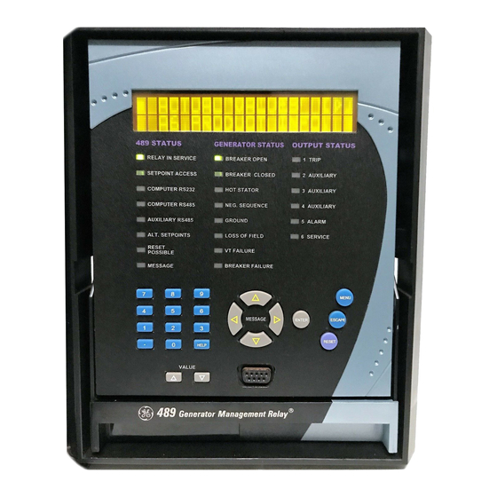
Page 63: Display
Digital Energy Multilin 489 Generator Management Relay Chapter 4: Interfaces Interfaces Faceplate Interface 4.1.1 Display All messages appear on a 40-character liquid crystal display. Messages are in plain English and do not require the aid of an instruction manual for deciphering. When the user interface is not being used, the display defaults to the user-defined status messages. - Page 64 CHAPTER 4: INTERFACES 489 Status LED Indicators • 489 IN SERVICE: Indicates that control power is applied, all monitored input/output and internal systems are OK, the 489 has been programmed, and is in protection mode, not simulation mode. When in simulation or testing mode, the LED indicator will flash.
-
Page 65: Rs232 Program Port
CHAPTER 4: INTERFACES • HOT STATOR: Indicates that the generator stator is above normal temperature when one of the stator RTD alarm or trip elements is picked up or the thermal model trip element is picked up. • NEG. SEQUENCE: Indicates that the negative sequence current alarm or trip element is picked up. - Page 66 CHAPTER 4: INTERFACES [ w ] ACTUAL VALUES [ w ] TARGET MESSAGES Press the key or the key from these main menu MESSAGE ENTER pages to display the corresponding menu page. Use the keys to scroll through the page MESSAGE MESSAGE headers.
- Page 67 CHAPTER 4: INTERFACES keys scroll through any active conditions in the relay. MESSAGE MESSAGE Diagnostic messages are displayed indicating the state of protection and monitoring elements that are picked up, operating, or latched. When the Message LED is on, there are messages to be viewed with the key by selecting target messages as described MENU...
-
Page 68: Setpoint Entry
CHAPTER 4: INTERFACES The 489 does not have '+' or '–' keys. Negative numbers may be entered in one of two manners. • Immediately pressing one of the keys causes the setpoint to VALUE scroll through its range including any negative numbers. •... - Page 69 CHAPTER 4: INTERFACES Press the keys to scroll through all the MESSAGE MESSAGE available setpoint page headers. Setpoint page headers look as follows: [ w ] SETPOINTS S1 489 SETUP To enter a given setpoints page, Press the key. MESSAGE ENTER Press the keys to scroll through sub-page...
-
Page 70: Diagnostic Messages
CHAPTER 4: INTERFACES 4.1.6 Diagnostic Messages Diagnostic messages are automatically displayed for any active conditions in the relay such as trips, alarms, or asserted logic inputs. These messages provide a summary of the present state of the relay. The Message LED flashes when there are diagnostic messages available;... -
Page 71: Flash Messages
CHAPTER 4: INTERFACES Table 4–1: Self-Test Warnings Message Severity Description This warning is caused by out of range reading Self-Test Warning 8 Major of self test RTD16. The integrity of system input Replace Immediately measurements is affected by this failure. Clock Not Set Minor Occurs if the clock has not been set. -
Page 72: Enervista Software Interface
RS232, RS485, and Ethernet (requires the MultiNet adapter) communications. The following figures below illustrate typical connections for RS232 and RS485 communications. For additional details on Ethernet communications, please see the MultiNet manual (GE Publication number GEK-106498). 4–10 489 GENERATOR MANAGEMENT RELAY – INSTRUCTION MANUAL... - Page 73 CHAPTER 4: INTERFACES FIGURE 4–2: Communications using The Front RS232 Port 489 GENERATOR MANAGEMENT RELAY – INSTRUCTION MANUAL 4–11 Courtesy of NationalSwitchgear.com...
-
Page 74: Installing The Enervista 489 Setup Software
• US Robotics external Sportster 56K X2 • PCTEL 2304WT V.92 MDC internal modem After ensuring these minimum requirements, use the following procedure to install the EnerVista 489 Setup software from the enclosed GE EnerVista CD. 4–12 489 GENERATOR MANAGEMENT RELAY – INSTRUCTION MANUAL... - Page 75 CHAPTER 4: INTERFACES Insert the GE EnerVista CD into your CD-ROM drive. Click the Install Now button and follow the installation instructions to install the no-charge EnerVista software on the local PC. When installation is complete, start the EnerVista Launchpad application.
- Page 76 CHAPTER 4: INTERFACES EnerVista Launchpad will obtain the latest installation software from the Web or CD and automatically start the installation process. A status window with a progress bar will be shown during the downloading process. Select the complete path, including the new directory name, where the EnerVista 489 Setup software will be installed.
-
Page 77: Connecting Enervista 489 Setup To The Relay
(for RS485 communications). See Hardware on page 4–10 for connection details. This example demonstrates an RS232 connection. For RS485 communications, the GE Multilin F485 converter will be required. Refer to the F485 manual for additional details. To configure the relay for Ethernet communications, see Configuring Ethernet Communications on page 4–17. -
Page 78: Using The Quick Connect Feature
CHAPTER 4: INTERFACES Select “Serial” from the Interface drop-down list. This will display a number of interface parameters that must be entered for proper RS232 functionality. Enter the slave address and COM port values (from the S1 489 SETUP menu) in the Slave Address and COM Port COMMUNICATIONS fields. -
Page 79: Configuring Ethernet Communications
CHAPTER 4: INTERFACES Press the Quick Connect button. The following window will appear: As indicated by the window, the Quick Connect feature quickly connects the EnerVista 489 Setup software to a 489 front port with the following setpoints: 9600 baud, no parity, 8 bits, 1 stop bit. - Page 80 CHAPTER 4: INTERFACES Install and start the latest version of the EnerVista 489 Setup software (available from the GE EnerVista CD). See the previous section for the installation procedure. Click on the Device Setup button to open the Device Setup window.
-
Page 81: Connecting To The Relay
CHAPTER 4: INTERFACES Click OK when the relay order code has been received. The new device will be added to the Site List window (or Online window) located in the top left corner of the main EnerVista 489 Setup window. The 489 Site Device has now been configured for Ethernet communications. - Page 82 CHAPTER 4: INTERFACES The Phase Overcurrent setpoint window will open with a corresponding status indicator on the lower left of the EnerVista 489 Setup window. If the status indicator is red, verify that the serial cable is properly connected to the relay, and that the relay has been properly configured for communications (steps described earlier).
-
Page 83: Working With Setpoints And Setpoint Files
CHAPTER 4: INTERFACES Working with Setpoints and Setpoint Files 4.4.1 Engaging a Device The EnerVista 489 Setup software may be used in on-line mode (relay connected) to directly communicate with a 489 relay. Communicating relays are organized and grouped by communication interfaces and into sites. Sites may contain any number of relays selected from the SR or UR product series. - Page 84 CHAPTER 4: INTERFACES Click the arrow at the end of the box to display a numerical keypad interface that allows the user to enter a value within the setpoint range displayed near the top of the keypad: Click Accept to exit from the keypad and keep the new value. Click on Cancel to exit from the keypad and retain the old value.
-
Page 85: Using Setpoint Files
CHAPTER 4: INTERFACES 4.4.3 Using Setpoint Files Overview The EnerVista 489 Setup software interface supports three ways of handling changes to relay setpoints: • In off-line mode (relay disconnected) to create or edit relay setpoint files for later download to communicating relays. •... - Page 86 CHAPTER 4: INTERFACES Select the File > Read Settings from Device menu item to obtain settings information from the device. After a few seconds of data retrieval, the software will request the name and destination path of the setpoint file. The corresponding file extension will be automatically assigned. Press Save to complete the process.
- Page 87 CHAPTER 4: INTERFACES Select the New Settings File item. The EnerVista 489 Setup software displays the following box, allowing for the configuration of the setpoint file for the correct firmware version. It is important to define the correct firmware version to ensure that setpoints not available in a particular version are not downloaded into the relay.
- Page 88 CHAPTER 4: INTERFACES Load the setpoint file to be upgraded into the EnerVista 489 Setup environment as described in Adding Setpoints Files to the Environment on page 4–24. In the File pane, select the saved setpoint file. From the main window menu bar, select the File > Properties menu item and note the version code of the setpoint file.
- Page 89 CHAPTER 4: INTERFACES Printing Setpoints and Actual Values The EnerVista 489 Setup software allows the user to print partial or complete lists of setpoints and actual values. Use the following procedure to print a list of setpoints: Select a previously saved setpoints file in the File pane or establish communications with a 489 device.
- Page 90 CHAPTER 4: INTERFACES Loading Setpoints from a File An error message will occur when attempting to download a setpoint file with a revision number that does not match the relay firmware. If the firmware has been upgraded since saving the setpoint file, see Upgrading Setpoint Files to a New Revision on page 4–25 for instructions on changing the revision number of a setpoint file.
- Page 91 CHAPTER 4: INTERFACES If there are no incompatibilities between the target device and the Setpoints file, the data will be transferred to the relay. An indication of the percentage completed will be shown in the bottom of the main menu. 489 GENERATOR MANAGEMENT RELAY –...
-
Page 92: Upgrading Relay Firmware
To upgrade the 489 firmware, follow the procedures listed in this section. Upon successful completion of this procedure, the 489 will have new firmware installed with the original setpoints. The latest firmware files are available from the GE Multilin website at http://www.GEmultilin.com. 4.5.2... - Page 93 The EnerVista 489 Setup software will request the new firmware file. Locate the file to load into the 489. The firmware filename has the following format: 32 J 300 A8 . 000 Modification Number (000 = none) GE Multilin use only Firmware version Required 489 hardware revision Product code (32 = 489) FIGURE 4–5: Firmware File Format...
- Page 94 CHAPTER 4: INTERFACES When communications is established, the saved setpoints must be reloaded back into the relay. See Loading Setpoints from a File on page 4–28 for details. Modbus addresses assigned to firmware modules, features, settings, and corresponding data items (i.e. default values, min/max values, data type, and item size) may change slightly from version to version of firmware.
-
Page 95: Advanced Enervista 489 Setup Features
CHAPTER 4: INTERFACES Advanced EnerVista 489 Setup Features 4.6.1 Triggered Events While the interface is in either on-line or off-line mode, data generated by triggered specified parameters can be viewed and analyzed via one of the following: • Event Recorder: The event recorder captures contextual data associated with the last 256 events, listed in chronological order from most recent to the oldest. - Page 96 CHAPTER 4: INTERFACES Click on the Save to File button to save the selected waveform to the local PC. A new window will appear requesting for file name and path. The file is saved as a CSV (comma delimited values) file, which can be viewed and manipulated with compatible third-party software.
-
Page 97: Phasors
CHAPTER 4: INTERFACES conditions at the time of the event. Additional information on how to download and save events is shown in Event Recorder on page 4–40. From the window main menu bar, press the Preference button to open the Setup page to change the graph attributes. Preference button The following window will appear: Change the Color of each graph as desired, and select other options, as... - Page 98 CHAPTER 4: INTERFACES Click on the Phasors tab. The EnerVista 489 Setup software will display the following window: Press the “View” button to display the following window: VOLTAGE LEVEL CURRENT LEVEL Displays the value Displays the value and the angle of and angle of the the voltage phasors current phasor...
-
Page 99: Trending (Data Logger)
CHAPTER 4: INTERFACES When the currents and voltages measured by the relay are zero, the angles displayed by the relay and those shown by the EnerVista 489 Setup software are not fixed values. 4.6.4 Trending (Data Logger) The trending or data logger feature is used to sample and record up to eight actual values at an interval defined by the user. - Page 100 CHAPTER 4: INTERFACES With EnerVista 489 Setup running and communications established, Select the Actual Values > Trending menu item to open the trending window. The following window will appear. To prepare for new trending, Select Stop to stop the data logger and Reset to clear the screen. Select the graphs to be displayed through the pull-down menu beside each channel description.
- Page 101 CHAPTER 4: INTERFACES To limit the size of the saved file, Enter a number in the Limit File Capacity To box. The minimum number of samples is 1000. At a sampling rate of 5 seconds (or 1 sample every 5 seconds), the file will contain data collected during the past 5000 seconds.
-
Page 102: Event Recorder
CHAPTER 4: INTERFACES 4.6.5 Event Recorder The 489 event recorder can be viewed through the EnerVista 489 Setup software. The event recorder stores generator and system information each time an event occurs (e.g. breaker failure). A maximum of 256 events can be stored. Each event is assigned an event number, from E001 to E256. -
Page 103: Modbus User Map
Modbus User Map The EnerVista 489 Setup software provides a means to program the 489 User Map (Modbus addresses 0180h to 01F7h). Refer to GE Publication GEK-106491: 489 Communications Guide for additional information on the User Map. Select a connected device in EnerVista 489 Setup. - Page 104 CHAPTER 4: INTERFACES • Generator status either stopped, starting, or running. It includes values such as generator load, thermal capacity used, generator speed, and instantaneous values of power system quantities. • The status of digital inputs. • Last trip information, including values such as cause of last trip, time and date of trip, generator speed and load at the time of trip, pre-trip temperature measurements, pre-trip analog inputs values, and pre-trip instantaneous values of power system quantities.
- Page 105 CHAPTER 4: INTERFACES Selecting an actual values window also opens the actual values tree from the corresponding device in the site list and highlights the current location in the hierarchy. For complete details on actual values, refer to Chapter 6. To view a separate window for each group of actual values, select the desired item from the tree, and double click with the left mouse button.
-
Page 106: Using Enervista Viewpoint With The 489
EnerVista Viewpoint. Information on license pricing can be found at http://www.EnerVista.com. Install the EnerVista Viewpoint software from the GE EnerVista CD. Ensure that the 489 device has been properly configured for either serial or Ethernet communications (see previous sections for details). - Page 107 CHAPTER 4: INTERFACES Enter the desired name in the Device Name field and a description (optional) of the site. Select the appropriate communications interface (Ethernet or Serial) and fill in the required information for the 489. See Connecting EnerVista 489 Setup to the Relay on page 4–15 for details. FIGURE 4–11: Device Setup Screen (Example) Click the Read Order Code button to connect to the 489 device and upload the order code.
- Page 108 CHAPTER 4: INTERFACES FIGURE 4–12: ‘Plug and Play’ Dashboard Click the Dashboard button below the 489 icon to view the device information. We have now successfully accessed our 489 through EnerVista Viewpoint. 4–46 489 GENERATOR MANAGEMENT RELAY – INSTRUCTION MANUAL Courtesy of NationalSwitchgear.com...
- Page 109 CHAPTER 4: INTERFACES FIGURE 4–13: EnerVista Plug and Play Screens For additional information on EnerVista viewpoint, please visit the EnerVista website at http://www.EnerVista.com. 489 GENERATOR MANAGEMENT RELAY – INSTRUCTION MANUAL 4–47 Courtesy of NationalSwitchgear.com...
- Page 110 CHAPTER 4: INTERFACES 4–48 489 GENERATOR MANAGEMENT RELAY – INSTRUCTION MANUAL Courtesy of NationalSwitchgear.com...
-
Page 111: Setpoint Message Map
Digital Energy Multilin 489 Generator Management Relay Chapter 5: Setpoints Setpoints Overview 5.1.1 Setpoint Message Map The 489 has a considerable number of programmable setpoints which makes it extremely flexible. The setpoints have been grouped into a number of pages and sub-pages as shown below. - Page 112 CHAPTER 5: SETPOINTS See page 5–18. SETPOINTS CURRENT MESSAGE See page 5–18. VOLTAGE MESSAGE See page 5–19. GENERATOR MESSAGE See page 5–20. SERIAL END OF PAGE MESSAGE See page 5–21. SETPOINTS BREAKER MESSAGE See page 5–22. GENERAL MESSAGE See page 5–22. GENERAL ↓...
- Page 113 CHAPTER 5: SETPOINTS See page 5–28. SETPOINTS RELAY END OF PAGE MESSAGE 1 SETPOINTS 1 OVERCURRENT See page 5–33. S5 CURRENT ELEM. ALARM 1 OFFLINE MESSAGE See page 5–33. OVERCURRENT 1 INADVERTENT MESSAGE See page 5–34. ENERGIZATION 1 PHASE MESSAGE See page 5–35.
- Page 114 CHAPTER 5: SETPOINTS 1 NEUTRAL U/V MESSAGE See page 5–53. (3rd HARMONIC) 1 LOSS OF MESSAGE See page 5–55. EXCITATION 1 DISTANCE MESSAGE See page 5–56. ELEMENT END OF PAGE MESSAGE 1 SETPOINTS 1 REACTIVE See page 5–61. S7 POWER ELEMENTS POWER 1 REVERSE MESSAGE...
- Page 115 CHAPTER 5: SETPOINTS END OF PAGE MESSAGE See page 5–90. SETPOINTS TRIP MESSAGE See page 5–90. BREAKER TRIP COIL MESSAGE See page 5–91. MONITOR VT FUSE MESSAGE See page 5–92. FAILURE MESSAGE See page 5–93. CURRENT MW DEMAND MESSAGE See page 5–93. Mvar DEMAND MESSAGE See page 5–93.
-
Page 116: Trips / Alarms/ Control Features
CHAPTER 5: SETPOINTS MESSAGE See page 5–98. ANALOG END OF PAGE MESSAGE See page 5–100. SETPOINTS SIMULATION PRE- MESSAGE See page 5–101. FAULT MESSAGE See page 5–102. FAULT MESSAGE See page 5–102. TEST MESSAGE See page 5–103. TEST MESSAGE See page 5–104. COMMUNICATION MESSAGE See page 5–104. -
Page 117: Relay Assignment Practices
CHAPTER 5: SETPOINTS Note that a lockout time will occur due to overload trip (see Model Setup on page 5–71 for additional details). Alarms A 489 alarm feature may be assigned to operate any combination of four output relays: 2 Auxiliary, 3 Auxiliary, 4 Auxiliary, and 5 Alarm. When an alarm becomes active, the appropriate LED (indicator) on the 489 faceplate will illuminate when an output relay(s) has operated. -
Page 118: Dual Setpoints
GE Multilin website at http://www.GEmultilin.com. See the Support Documents section of the 489 Generator Management Relay page for the latest version. This document is also available in print from the GE Multilin literature department (request publication number GET-8445). -
Page 119: S1 489 Setup
CHAPTER 5: SETPOINTS S1 489 Setup 5.2.1 Passcode PATH: SETPOINTS S1 489 SETUP PASSCODE Range: 1 to 8 numeric digits PASSCODE ENTER PASSCODE FOR ACCESS: Range: Permitted, Restricted SETPOINT ACCESS: MESSAGE Permitted Range: No, Yes CHANGE PASSCODE: MESSAGE A passcode access security feature is provided with the 489. The passcode is defaulted to “0”... -
Page 120: Preferences
If an invalid passcode is entered, the encrypted passcode is viewable by pressing HELP Consult GE Multilin with this number if the currently programmed passcode is unknown. The passcode can be determined with deciphering software. 5.2.2... - Page 121 CHAPTER 5: SETPOINTS value of 25%, for example, when the is “7 x 16" cycles, WAVEFORM MEMORY BUFFER would produce a waveform of 4 pre-trip cycles and 12 post-trip cycles. • WAVEFORM MEMORY BUFFER: Selects the partitioning of the waveform memory. The first number indicates the number of events and the second number, the number of cycles.
- Page 122 The computer RS485 port is a general purpose port for connection to a DCS, PLC, or PC. The Auxiliary RS485 port may also be used as another general purpose port or it may be used to talk to Auxiliary GE Multilin devices in the future. 5–12 489 GENERATOR MANAGEMENT RELAY –...
-
Page 123: Communications
CHAPTER 5: SETPOINTS Ethernet Communications The following setpoints appear when the relay is ordered with the Ethernet (T) option. PATH: SETPOINTS S1 489 SETUP COMMUNICATIONS Range: 1 to 254 in steps of 1 SLAVE ADDRESS: COMMUNICATIONS Range: 300, 1200, 2400, 4800, 9600, COMPUTER RS485 MESSAGE 19200... -
Page 124: Default Messages
DATE: 01/01/1995 MESSAGE TIME: 12:00:00 Range: N/A GE MULTILIN MESSAGE 489 GENERATOR RELAY The 489 displays default messages after a period of keypad inactivity. Up to 20 default messages can be selected for display. If more than one message is chosen, they will... -
Page 125: Message Scratchpad
CHAPTER 5: SETPOINTS scratchpad. For example, the relay could be set to alternately scan a generator identification message, the current in each phase, and the hottest stator RTD. Currently selected default messages can be viewed in subgroup. DEFAULT MESSAGES Default messages can be added to the end of the default message list, as follows: Enter the correct passcode at S1 489 SETUP PASSCODE... -
Page 126: Clear Data
Range: 40 alphanumeric characters TEXT 4 MESSAGE Range: 40 alphanumeric characters GE MULTILIN MESSAGE 489 GENERATOR RELAY Up to 5 message screens can be programmed under the message scratchpad area. These messages may be notes that pertain to the installation of the generator. In addition, these notes may be selected for scanning during default message display. - Page 127 CHAPTER 5: SETPOINTS Range: No, Yes CLEAR BREAKER MESSAGE INFORMATION: No These commands may be used to clear various historical data. • CLEAR LAST TRIP DATA: The Last Trip Data may be cleared by executing this command. • CLEAR MWh and Mvarh METERS: Executing this command will clear the MWh and Mvarh metering to zero.
-
Page 128: S2 System Setup
CHAPTER 5: SETPOINTS S2 System Setup 5.3.1 Current Sensing PATH: SETPOINTS S2 SYSTEM SETUP CURRENT SENSING Range: 1 to 5000 in steps of 1, Not PHASE CT PRIMARY: Programmed CURRENT ------------- Range: None, 1A Secondary, 5A GROUND CT: MESSAGE Secondary, 50:0.025 50:0.025 Range: 10 to 10000 in steps of 1. -
Page 129: Generator Parameters
CHAPTER 5: SETPOINTS setpoint is seen only if setpoint is Note NEUTRAL VT RATIO NEUTRAL VOLTAGE TRANSFORMER “Yes”. The voltage transformer connections and turns ratio are entered here. The VT should be selected such that the secondary phase-phase voltage of the VTs is between 70.0 and 135.0 V when the primary is at generator rated voltage. -
Page 130: Serial Start/Stop Initiation
EVENTS: Off If enabled, this feature will allow the user to initiate a generator startup or shutdown via the RS232/RS485 communication ports. Refer to GE publication number GEK-106495: 489 Communications Guide for command formats. When a startup command is issued, the auxiliary relay(s) assigned for starting control will be activated for 1 second to initiate startup. -
Page 131: S3 Digital Inputs
CHAPTER 5: SETPOINTS S3 Digital Inputs 5.4.1 Description The 489 has nine (9) digital inputs for use with external contacts. Two of the 489 digital inputs have been pre-assigned as inputs having a specific function. The Access Switch does not have any setpoint messages associated with it. The Breaker Status input, may be configured for either an 'a' or 'b' auxiliary contact. -
Page 132: General Input Atog
CHAPTER 5: SETPOINTS 5.4.3 General Input A to G PATH: SETPOINTS S3 DIGITAL INPUTS GENERAL INPUT A(G) Range: None, Input 1 to Input 7. See ASSIGN DIGITAL note below. GENERAL INPUT: None Range: Closed, Open ASSERTED DIGITAL MESSAGE INPUT STATE: Closed Range: 12 alphanumeric characters INPUT NAME: MESSAGE... -
Page 133: Remote Reset
CHAPTER 5: SETPOINTS Inputs may be configured for control, alarm, or trip. If the control feature is enabled, the assigned output relay(s) operate when the input is asserted. If the PULSED CONTROL RELAY is set to “0”, the output relay(s) operate only while the input is asserted. DWELL TIME However, if a dwell time is assigned, the output relay(s) operate as soon as the input is asserted for a period of time specified by the setpoint. -
Page 134: Dual Setpoints
CHAPTER 5: SETPOINTS 5.4.7 Dual Setpoints PATH: SETPOINTS S3 DIGITAL INPUTS DUAL SETPOINTS Range: None, Input 1, Input 2, Input 3, ASSIGN DIGITAL Input 4, Input 5, Input 6, Input 7 DUAL INPUT: None Range: Group 1, Group 2 ACTIVATE SETPOINT MESSAGE GROUP: Group 1 Range: Group 1, Group 2... -
Page 135: Sequential Trip
CHAPTER 5: SETPOINTS The active group can be selected using the setpoint or the ACTIVATE SETPOINT GROUP assigned digital input (shorting that input will activate the alternate set of protection setpoints, Group 2). In the event of a conflict between the ACTIVATE SETPOINT GROUP setpoint or the assigned digital input, Group 2 will be activated. -
Page 136: Field-Breaker
CHAPTER 5: SETPOINTS 5.4.9 Field-Breaker PATH: SETPOINTS S3 DIGITAL INPUTS FIELD-BREAKER DISCREPANCY Range: None, Input 1 to Input 7 FIELD- ASSIGN DIGITAL BREAKER INPUT: None Range: Auxiliary a, Auxiliary b FIELD STATUS MESSAGE CONTACT: Auxiliary a Range: Any combination of Relays 1 to ASSIGN TRIP MESSAGE RELAYS (1-4): 1---... -
Page 137: Waveform Capture
CHAPTER 5: SETPOINTS Range: 101 to 175% in steps of 1 TACHOMETER TRIP MESSAGE SPEED: 110% Rated Range: 1 to 250 s in steps of 1 TACHOMETER TRIP MESSAGE DELAY: 1 s One of assignable digital inputs 4 to 7 may be assigned to the tachometer function to measure mechanical speed. -
Page 138: S4 Output Relays
CHAPTER 5: SETPOINTS S4 Output Relays 5.5.1 Description Five of the six output relays are always non-failsafe; the 6 Service relay is always failsafe. As a failsafe, the 6 Service relay will be energized normally and de-energize when called upon to operate. It will also de-energize when control power to the 489 is lost and therefore, be in its operated state. -
Page 139: S5 Current Elements
Inverse Time Overcurrent Curve Characteristics Description The 489 inverse time overcurrent curves may be either ANSI, IEC, or GE Type IAC standard curve shapes. This allows for simplified coordination with downstream devices. If however, none of these curve shapes is adequate, the FlexCurve™ may be used to customize the inverse time curve characteristics. - Page 140 CHAPTER 5: SETPOINTS ANSI Curves The ANSI time overcurrent curve shapes conform to industry standard curves and fit into the ANSI C37.90 curve classifications for extremely, very, normally, and moderately inverse. The 489 ANSI curves are derived from the formula: ⎛...
- Page 141 CHAPTER 5: SETPOINTS IAC Curves The curves for the General Electric type IAC relay family are derived from the formula: ⎛ ⎞ × ⎜ ⎟ ----------------------------------- - ------------------------------------------ - ------------------------------------------ - (EQ 0.6) ⁄ ⎝ ⎠ ⁄ ⁄ – – –...
- Page 142 CHAPTER 5: SETPOINTS Table 5–5: FlexCurve™ Trip Times Pickup Trip Pickup Trip Pickup Trip Pickup Trip Time Time Time Time (ms) (ms) (ms) (ms) 1.03 10.5 1.05 11.0 11.5 12.0 12.5 13.0 13.5 14.0 14.5 15.0 15.5 16.0 16.5 17.0 17.5 18.0 18.5...
-
Page 143: Overcurrent Alarm
CHAPTER 5: SETPOINTS 5.6.2 Overcurrent Alarm PATH: SETPOINTS S5 CURRENT ELEM. OVERCURRENT ALARM Range: Off, Latched, Unlatched 1 OVERCURRENT OVERCURRENT ALARM ALARM: Off Range: Any combination of Relays 2 to ASSIGN ALARM MESSAGE RELAYS (2-5): ---5 Range: 0.10 to 1.50 × FLA in steps of OVERCURRENT ALARM MESSAGE 0.01... -
Page 144: Inadvertent Energization
CHAPTER 5: SETPOINTS If the unit auxiliary transformer is on the generator side of the breaker, the pickup level Note must be set greater than the unit auxiliary load. 5.6.4 Inadvertent Energization PATH: SETPOINTS S5 CURRENT ELEM. INADVERTENT ENERG. Range: Off, Latched, Unlatched 1 INADVERTENT INADVERTENT ENERGIZE ENERGIZATION... -
Page 145: Phase Overcurrent
CTs is used to time out against an inverse time curve. The 489 inverse time curve for this element may be either ANSI, IEC, or GE Type IAC standard curve shapes. This allows for simplified coordination with downstream devices. If these curve shapes are not adequate, FlexCurves™... -
Page 146: Negative Sequence
CHAPTER 5: SETPOINTS • “Yes” ENABLE VOLTAGE RESTRAINT: • : 10% VOLTAGE LOWER LIMIT • Phase-Phase Voltage / Rated Phase-Phase Voltage = 0.4 p.u. V The voltage restrained phase overcurrent pickup level is calculated as follows: Pickup Phase OC Pickup ×... - Page 147 CHAPTER 5: SETPOINTS Range: 0.0 to 999.9 s in steps of 0.01 NEG. SEQUENCE O/C MESSAGE RESET RATE: 227.0 s Rotor heating in generators due to negative sequence current is a well known phenomenon. Generators have very specific capability limits where unbalanced current is concerned (see ANSI C50.13).
-
Page 148: Ground Overcurrent
The 489 inverse time curve for this element may be either ANSI, IEC, or GE Type IAC standard curve shapes. This allows for simplified coordination with downstream devices. If however, none of these curves shapes is adequate, the FlexCurve™... -
Page 149: Phase Differential
CHAPTER 5: SETPOINTS For example, if the ground CT is 50:0.025, a pickup of 0.20 would be 0.20 × 50 = 10 A primary. If the ground CT is 50:0.025, a pickup of 0.05 would be 0.05 × 50 = 2.5 A primary. 5.6.8 Phase Differential PATH: SETPOINTS... -
Page 150: Ground Directional
CHAPTER 5: SETPOINTS The differential element for phase A will operate when: > × (EQ 5.12) operate restraint where the following hold: operate current (EQ 5.13) operate -------------------- restraint current (EQ 5.14) restraint characteristic slope of the differential element in percent (EQ 5.15) Slope1 if I <... - Page 151 CHAPTER 5: SETPOINTS Range: 0.1 to 120.0 sec. in steps of 0.1 GROUND DIR. ALARM MESSAGE DELAY: 3.0 sec. Range: On, Off GROUND DIR. ALARM MESSAGE EVENTS: Off Range: Off, Latched, Unlatched GROUND DIRECTIONAL MESSAGE TRIP: Off Range: Any combination of Relays 1 to ASSIGN TRIP MESSAGE RELAYS (1-4): 1---...
-
Page 152: High-Set Phase Oc
CHAPTER 5: SETPOINTS AUXILIARY CONTACT GROUNDING SWITCH C(B) C(B) B(C) B(C) TO 50:0.025 TO Vneutral OF EACH 489 GROUND 50:0.025 INPUTS 808812A3.CDR FIGURE 5–5: Ground Directional Detection 5.6.10 High-Set Phase OC PATH: SETPOINTS S5 CURRENT ELEM. HIGH-SET PHASE OVERCURRENT Range: Off, Latched, Unlatched 1 HIGH-SET HIGH-SET PHASE O/C PHASE OVERCURRENT... -
Page 153: S6 Voltage Elements
CHAPTER 5: SETPOINTS S6 Voltage Elements 5.7.1 Undervoltage PATH: SETPOINTS S6 VOLTAGE ELEM. UNDERVOLTAGE Range: Off, Latched, Unlatched 1 UNDERVOLTAGE UNDERVOLTAGE ALARM: Off Range: Any combination of Relays 2 to ASSIGN ALARM MESSAGE RELAYS (2-5): ---5 Range: 0.50 to 0.99 × Rated in steps of UNDERVOLTAGE ALARM MESSAGE 0.01... -
Page 154: Overvoltage
CHAPTER 5: SETPOINTS where: T = trip time in seconds setpoint UNDERVOLTAGE TRIP DELAY V = actual average phase-phase voltage setpoint UNDERVOLTAGE TRIP PICKUP pickup 1000 Multiples of Undervoltage Pickup 808742A1.CDR FIGURE 5–6: Undervoltage Curves 5.7.2 Overvoltage PATH: SETPOINTS S6 VOLTAGE ELEM. OVERVOLTAGE Range: Off, Latched, Unlatched 1 OVERVOLTAGE... -
Page 155: Volts/Hertz
CHAPTER 5: SETPOINTS Range: 0.0 to 999.9 s in steps of 0.1 OVERVOLTAGE CURVE MESSAGE RESET RATE: 1.4 s Range: Curve, Definite Time OVERVOLTAGE CURVE MESSAGE ELEMENT: Curve The overvoltage elements may be used for protection of the generator and/or its auxiliary equipment during prolonged overvoltage conditions. - Page 156 CHAPTER 5: SETPOINTS Range: 0.50 to 1.99 ×Nominal in steps VOLTS/HERTZ ALARM MESSAGE of 0.01 PICKUP: 1.00 xNominal Range: 0.1 to 150.0 s in steps of 0.1 VOLTS/HERTZ ALARM MESSAGE DELAY: 3.0 s Range: On, Off VOLTS/HERTZ ALARM MESSAGE EVENTS: Off Range: Off, Latched, Unlatched VOLTS/HERTZ MESSAGE...
- Page 157 CHAPTER 5: SETPOINTS The V/Hz Curve 1 trip curves are shown below for delay settings of 0.1, 0.3, 1, 3, and 10 seconds. 1000 0.01 1.00 1.20 1.40 1.60 1.80 2.00 Multiples of Volts/Hertz Pickup 808743A1-X1.CDR The formula for Volts/Hertz Curve 2 is: -- - >...
-
Page 158: Phase Reversal
CHAPTER 5: SETPOINTS The formula for Volts/Hertz Curve 3 is: , when -- - > Pickup ---------------------------------------------------------------------- - (EQ 5.22) V F ⁄ ⎛ ⎞ ------------------------------------------------- - – ⎝ ⎠ ⁄ × Pickup where: T = trip time in seconds setpoint VOLTS/HERTZ TRIP DELAY V = RMS measurement of Vab... -
Page 159: Underfrequency
CHAPTER 5: SETPOINTS and the phase rotation is not the same as the setpoint. Loss of VT fuses cannot be detected when the generator is offline and could lead to maloperation of this element. If the VT type is selected as “None”, the phase reversal protection is disabled. 5.7.5 Underfrequency PATH: SETPOINTS... -
Page 160: Overfrequency
CHAPTER 5: SETPOINTS 5.7.6 Overfrequency PATH: SETPOINTS S6 VOLTAGE ELEM. OVERFREQUENCY Range: 0 to 5 s in steps of 1 1 OVERFREQUENCY BLOCK OVERFREQUENCY FROM ONLINE: 1 s Range: 0.50 to 0.99 × Rated in steps of VOLTAGE LEVEL MESSAGE 0.01 CUTOFF: 0.50 x Rated Range: Off, Latched, Unlatched... -
Page 161: Neutral Overvoltage
CHAPTER 5: SETPOINTS 5.7.7 Neutral Overvoltage PATH: SETPOINTS S6 VOLTAGE ELEM. NEUTRAL O/V (FUNDAMENTAL) Range: Yes, No 1 NEUTRAL O/V SUPERVISE WITH (FUNDAMENTAL) DIGITAL INPUT: No Range: Off, Latched, Unlatched NEUTRAL OVERVOLTAGE MESSAGE ALARM: Off Range: Any combination of Relays 2 to ASSIGN ALARM MESSAGE RELAYS (2-5): ---5... - Page 162 CHAPTER 5: SETPOINTS where T = trip time in seconds setpoint NEUTRAL OVERVOLTAGE TRIP DELAY V = neutral voltage setpoint NEUTRAL O/V TRIP LEVEL pickup The neutral overvoltage curves are shown below. Refer to Appendix B for Application Notes. 1000 Multiples of Overvoltage Pickup 808741A1.CDR FIGURE 5–8: Neutral Overvoltage Curves...
-
Page 163: Neutral Undervoltage
CHAPTER 5: SETPOINTS 5.7.8 Neutral Undervoltage PATH: SETPOINTS S6 VOLTAGE ELEM. NEUTRAL U/V (3RD HARMONIC) Range: 0.02 to 0.99 × Rated MW in 1 NEUTRAL U/V LOW POWER BLOCKING steps of 0.01 (3rd HARMONIC) LEVEL: 0.05 x Rated Range: 0.50 to 1.00 × Rated in steps of LOW VOLTAGE BLOCKING MESSAGE 0.01... - Page 164 CHAPTER 5: SETPOINTS Neutral VT Ratio ′ > 0.25 V and V ′ ≥ Threshold 17 × × --------------------------------------- - (EQ 5.25) Phase VT Ratio where: V = magnitude of the third harmonic voltage at generator neutral; = magnitude of the third harmonic voltage at the generator terminals ´...
-
Page 165: Loss Of Excitation
CHAPTER 5: SETPOINTS 5.7.9 Loss of Excitation PATH: SETPOINTS S6 VOLTAGE ELEM. LOSS OF EXCITATION Range: Yes, No 1 LOSS OF ENABLE VOLTAGE EXCITATION SUPERVISION: Yes Range: 0.70 to 1.00 × Rated in steps of VOLTAGE MESSAGE 0.01 LEVEL: 0.70 x Rated Range: Off, Latched, Unlatched CIRCLE 1 MESSAGE... -
Page 166: Distance Element
CHAPTER 5: SETPOINTS All relay quantities are in terms of secondary impedances. The formula to convert primary impedance quantities to secondary impedance quantities is provided below. × CT Ratio primary ----------------------------------------------- - (EQ 5.27) ondary VT Ratio where: Z = primary ohms impedance; primary CT Ratio = programmed CT ratio, if CT ratio is 1200:5 use a value of 1200 / 5 = 240;... - Page 167 CHAPTER 5: SETPOINTS Range: 0.1 to 500.0 Ωsec in steps of 0.1 ZONE #2 MESSAGE REACH: 15.0 Ωsec Range: 50 to 85° in steps of 1 ZONE #2 MESSAGE ANGLE: 75° Range: 0.0 to 150.0 s in steps of 0.1 ZONE #2 TRIP MESSAGE DELAY: 2.0 s...
- Page 168 CHAPTER 5: SETPOINTS the step-up transformer connection. If this setting is chosen as “None”, then it is assumed that the transformer is Wye-Wye connected or that there is no step-up transformer. In this case the element will use the following operating quantities. Element Voltage Current...
- Page 169 CHAPTER 5: SETPOINTS Characteristic angle 808838A2.CDR FIGURE 5–12: Distance Element Characteristics 489 GENERATOR MANAGEMENT RELAY – INSTRUCTION MANUAL 5–59 Courtesy of NationalSwitchgear.com...
-
Page 170: S7 Power Elements
CHAPTER 5: SETPOINTS S7 Power Elements 5.8.1 Power Measurement Conventions Generation of power will be displayed on the 489 as positive watts. By convention, an induction generator normally requires reactive power from the system for excitation. This is displayed on the 489 as negative vars. A synchronous generator on the other hand has its own source of excitation and can be operated with either lagging or leading power factor. - Page 171 CHAPTER 5: SETPOINTS 5.8.2 Reactive Power PATH: SETPOINTS S7 POWER ELEMENTS REACTIVE POWER Range: 0 to 5000 s in steps of 1 1 REACTIVE BLOCK Mvar ELEMENT POWER FROM ONLINE: 1 s Range: Off, Latched, Unlatched REACTIVE POWER MESSAGE ALARM: Off Range: Any combination of Relays 2 to ASSIGN ALARM MESSAGE...
-
Page 172: Reverse Power
CHAPTER 5: SETPOINTS For example, given Rated MVA = 100 MVA and Rated Power Factor = 0.85, we have – Rated Mvars Rated MVA × Rated PF (EQ 5.28) – × 0.85 52.67 Mvars 5.8.3 Reverse Power PATH: SETPOINTS S7 POWER ELEMENTS REVERSE POWER Range: 0 to 5000 s in steps of 1 1 REVERSE... -
Page 173: Low Forward Power
CHAPTER 5: SETPOINTS Users are cautioned that a reverse power element may not provide reliable indication when set to a very low setting, particularly under conditions of large reactive loading on the generator. Under such conditions, low forward power is a more reliable element. 5.8.4 Low Forward Power PATH: SETPOINTS... -
Page 174: S8 Rtd Temperature
CHAPTER 5: SETPOINTS S8 RTD Temperature 5.9.1 RTD Types PATH: SETPOINTS S8 RTD TEMPERATURE RTD TYPES Range: 100 Ohm Platinum, 120 Ohm 1 RTD TYPES STATOR RTD TYPE: Nickel, 100 Ohm Nickel, 10 Ohm 100 Ohm Platinum Copper Range: as above BEARING RTD TYPE: MESSAGE 100 Ohm Platinum... -
Page 175: Rtd S 1 To 6
CHAPTER 5: SETPOINTS Table 5–6: RTD Temperature vs. Resistance Temperature 100 Ω Pt 120 Ω Ni 100 Ω Ni 10 Ω Cu (DIN 43760) ° C ° F 168.47 280.77 233.97 16.00 172.46 291.96 243.30 16.39 175.84 303.46 252.88 16.78 179.51 315.31 262.76... -
Page 176: Rtd S 7 To 10
CHAPTER 5: SETPOINTS 5.9.3 RTDs 7 to 10 PATH: SETPOINTS S8 RTD TEMPERATURE RTD #7(10) Range: Stator, Bearing, Ambient, Other, 1 RTD #7 RTD #7 APPLICATION: None Bearing Range: 8 alphanumeric characters RTD #7 NAME: MESSAGE Range: Off, Latched, Unlatched RTD #7 ALARM: MESSAGE Range: Any combination of Relays 2 to... -
Page 177: Rtd 11
CHAPTER 5: SETPOINTS 5.9.4 RTD 11 PATH: SETPOINTS S8 RTD TEMPERATURE RTD #11 Range: Stator, Bearing, Ambient, Other, 1 RTD #11 RTD #11 APPLICATION: None Other Range: 8 alphanumeric characters RTD #11 NAME: MESSAGE Range: Off, Latched, Unlatched RTD #11 ALARM: MESSAGE Range: Any combination of Relays 2 to ASSIGN ALARM... -
Page 178: Open Rtd Sensor
CHAPTER 5: SETPOINTS Range: 1 to 250°C in steps of 1 RTD #12 ALARM MESSAGE TEMPERATURE: 60°C Range: On, Off RTD #12 ALARM MESSAGE EVENTS: Off Range: Off, Latched, Unlatched RTD #12 TRIP: MESSAGE Range: RTD #1 to RTD #12 RTD #12 TRIP VOTING: MESSAGE RTD #12... -
Page 179: Rtd Short/Low Temp
CHAPTER 5: SETPOINTS 5.9.7 RTD Short/Low Temp PATH: SETPOINTS S8 RTD TEMPERATURE RTD SHORT/LOW TEMP Range: Off, Latched, Unlatched 1 RTD RTD SHORT/LOW TEMP SHORT/LOW TEMP ALARM: Off Range: Any combination of Relays 2 to ASSIGN ALARM MESSAGE RELAYS (2-5): ---5 Range: On, Off RTD SHORT/LOW TEMP MESSAGE... -
Page 180: S9 Thermal Model
CHAPTER 5: SETPOINTS 5.10 S9 Thermal Model 5.10.1 489 Thermal Model The thermal model of the 489 is primarily intended for induction generators, especially those that start on the system bus in the same manner as induction motors. However, some of the thermal model features may be used to model the heating that occurs in synchronous generators during overload conditions. -
Page 181: Model Setup
CHAPTER 5: SETPOINTS HIGH INERTIA RUNNING OVERLOAD MOTOR A,B,AND C ARE THE ACCELERATION THERMAL LIMIT CURVES AT 100%, 90%, AND 80%VOLTAGE, REPECTIVELY E,F, AND G ARE THE SAFE STALL THERMAL LIMIT TIMES AT 100%, 90%, AND 80%VOLTAGE, REPECTIVELY % CURRENT 806827A1.CDR FIGURE 5–14: Typical Time-Current and Thermal Limit Curves (ANSI/IEEE C37.96) - Page 182 CHAPTER 5: SETPOINTS Range: 0 to 250°C in steps of 1 RTD BIAS CENTER MESSAGE POINT: 130°C Range: 0 to 250°C in steps of 1 RTD BIAS MESSAGE MAXIMUM: 155°C Range: Standard, Custom, Voltage SELECT CURVE STYLE: MESSAGE Dependent Standard Range: 1 to 15 in steps of 1.
- Page 183 CHAPTER 5: SETPOINTS The generator FLA is calculated as: Note Generator Rated MVA ------------------------------------------------------------------------------------------------------------- - (EQ 5.29) × Rated Generator Phase-Phase Voltage The 489 integrates both stator and rotor heating into one model. Machine heating is reflected in a register called Thermal Capacity Used. If the machine has been stopped for a long period of time, it will be at ambient temperature and thermal capacity used should be zero.
- Page 184 CHAPTER 5: SETPOINTS 100000 10000 1000 1.00 0.10 1.00 1000 MULTIPLE OF FULL LOAD AMPS 806804A5.CDR FIGURE 5–15: 489 Standard Overload Curves Above 8.0 × Pickup, the trip time for 8.0 is used. This prevents the overload curve from Note acting as an instantaneous element.
- Page 185 CHAPTER 5: SETPOINTS Table 5–7: 489 Standard Overload Curve Multipliers PICKUP STANDARD CURVE MULTIPLIERS (× FLA) × 1 × 2 × 3 × 4 × 5 × 6 × 7 × 8 × 9 × 10 × 11 × 12 ×...
- Page 186 CHAPTER 5: SETPOINTS Table 5–7: 489 Standard Overload Curve Multipliers PICKUP STANDARD CURVE MULTIPLIERS (× FLA) × 1 × 2 × 3 × 4 × 5 × 6 × 7 × 8 × 9 × 10 × 11 × 12 ×...
- Page 187 CHAPTER 5: SETPOINTS TYPICAL CUSTOM CURVE GE Multilin 10000 PROGRAMMED 469 CUSTOM CURVE RUNNING SAFETIME (STATOR LIMIT) ACCELERATION SAFETIME (ROTOR LIMIT) MACHINE CURRENT @ 100% VOLTAGE 1000 MACHINE CURRENT @ 80% VOLTAGE MULTIPLE OF FULL LOAD CURRENT SETPOINT 808825A3.CDR FIGURE 5–16: Custom Curve Example...
- Page 188 CHAPTER 5: SETPOINTS limit curve adjusted accordingly. If the VT Connection setpoint is set to none or if a VT fuse failure is detected, the acceleration thermal limit curve for the minimum allowable voltage will be used. The voltage dependent overload curve is comprised of the three characteristic thermal limit curve shapes determined by the stall or locked rotor condition, acceleration, and running overload.
- Page 189 CHAPTER 5: SETPOINTS THERMAL LIMITS GE Multilin FOR HIGH INERTIAL LOAD 1000 1- Running Overload Thermal Limit 2- Acceleration Thermal Limit @ 80%V 3- Acceleration Thermal Limit @ 100%V 4- Locked Rotor Thermal Limit - Machine Acceleration Curve @ 80% V...
- Page 190 CHAPTER 5: SETPOINTS VOLTAGE DEPENDENT OVERLOAD (CUSTOM CURVE) GE Multilin 1000 Acceleration Intersect at 80%V Acceleration Intersect at 100%V MULTIPLES OF FULL LOAD AMPS 808827A3.CDR FIGURE 5–18: Voltage Dependent Overload Curve (Custom) Enter the per unit current value for the acceleration overload curve intersect with the custom curve for 80% voltage.
- Page 191 CHAPTER 5: SETPOINTS VOLTAGE DEPENDENT OVERLOAD (ACCELERATION CURVES) GE Multilin 1000 489 Custom Curve MULTIPLES OF FULL LOAD AMPS 808828A3.CDR FIGURE 5–19: Voltage Dependent Overload Curve (Acceleration Curves) 489 GENERATOR MANAGEMENT RELAY – INSTRUCTION MANUAL 5–81 Courtesy of NationalSwitchgear.com...
- Page 192 100% voltage and multiplying by 1.10. For trip times above the 110% voltage level, the trip time of 110% will be used (see the figure below). VOLTAGE DEPENDENT GE Multilin OVERLOAD PROTECTION CURVES 1000...
- Page 193 The following curves illustrate the resultant overload protection for 80% and 100% voltage, respectively. For voltages between these levels, the 489 shifts the acceleration curve linearly and constantly based upon the measured voltage during generator start. VOLTAGE DEPENDENT GE Multilin OVERLOAD PROTECTION at 80% V 1000 MULTIPLES OF FULL LOAD AMPS 808830A3.CDR...
- Page 194 CHAPTER 5: SETPOINTS VOLTAGE DEPENDENT GE Multilin OVERLOAD PROTECTION at 100% V 1000 MULTIPLES OF FULL LOAD AMPS 808829A3.CDR FIGURE 5–22: Voltage Dependent Overload Protection at 100% Voltage Unbalance Bias Unbalanced phase currents will cause additional rotor heating that will not be accounted for by electromechanical relays and may not be accounted for in some electronic protective relays.
- Page 195 6 × FLA and a negative sequence impedance of 0.167, voltage unbalances of 1, 2, 3, 4, and 5% equal current unbalances of 6, 12, 18, 24, and 30%, respectively. Based on this assumption, the GE curve illustrates the amount of machine derating for different values of k entered for the setpoint.
- Page 196 CHAPTER 5: SETPOINTS generator is assumed to be running if current is measured or the generator is online). A machine with a stopped rotor normally cools significantly slower than one with a turning rotor. Machine cooling is calculated using the following formulae: t τ...
- Page 197 CHAPTER 5: SETPOINTS Hot/Cold Safe Stall Ratio When thermal limit information is available for both a hot and cold machine, the 489 thermal model will adapt for the conditions if the HOT/COLD SAFE STALL RATIO programmed. The value entered for this setpoint dictates the level of thermal capacity used that the relay will settle at for levels of current that are below the OVERLOAD PICKUP .
- Page 198 CHAPTER 5: SETPOINTS where: RTD_Bias_TC = TC used due to hottest stator RTD used Temp = current temperature of the hottest stator RTD actual Temp = RTD Bias minimum setpoint Temp = RTD Bias center setpoint center Temp = RTD Bias maximum setpoint = TC used defined by the setpoint HOT/COLD SAFE STALL RATIO...
-
Page 199: Thermal Elements
CHAPTER 5: SETPOINTS 5.10.3 Thermal Elements SETPOINTS S9 THERMAL MODEL THERMAL ELEMENTS Range: Off, Latched, Unlatched 1 THERMAL THERMAL MODEL ELEMENTS ALARM: Off Range: Any combination of Relays ASSIGN ALARM MESSAGE 2 to 5 RELAYS (2-5): ---5 Range: 10 to 100% Used in steps of 1 THERMAL ALARM MESSAGE LEVEL: 75% Used... -
Page 200: S10 Monitoring
CHAPTER 5: SETPOINTS 5.11 S10 Monitoring 5.11.1 Trip Counter PATH: SETPOINTS S10 MONITORING TRIP COUNTER Range: Off, Latched, Unlatched TRIP COUNTER TRIP ALARM: Off Range: Any combination of Relays 2 to ASSIGN ALARM MESSAGE RELAYS (2-5): ---5 Range: 1 to 50000 Trips in steps of 1 TRIP COUNTER ALARM MESSAGE LEVEL: 25 Trips... -
Page 201: Trip Coil Monitor
CHAPTER 5: SETPOINTS 5.11.3 Trip Coil Monitor PATH: SETPOINTS S10 MONITORING TRIP COIL MONITOR Range: Off, Latched, Unlatched TRIP COIL TRIP COIL MONITOR MONITOR ALARM: Off Range: Any combination of Relays 2 to ASSIGN ALARM MESSAGE RELAYS (2-5): ---5 Range: 52 Closed, 52 Open/Closed SUPERVISION OF TRIP MESSAGE COIL: 52 Closed... -
Page 202: Vt Fuse Failure
CHAPTER 5: SETPOINTS 5.11.4 VT Fuse Failure PATH: SETPOINTS S10 MONITORING VT FUSE FAILURE Range: Off, Latched, Unlatched VT FUSE VT FUSE FAILURE FAILURE ALARM: Off Range: Any combination of Relays 2 to ASSIGN ALARM MESSAGE RELAYS (2-5): ---5 Range: On, Off VT FUSE FAILURE MESSAGE ALARM EVENTS: Off... -
Page 203: Demand
CHAPTER 5: SETPOINTS 5.11.5 Demand PATH: SETPOINTS S10 MONITORING CURRENT DEMAND... Range: 5 to 90 min. in steps of 1 CURRENT DEMAND CURRENT PERIOD: 15 min. Range: Off, Latched, Unlatched CURRENT DEMAND MESSAGE ALARM: Off Range: Any combination of Relays 2 to ASSIGN ALARM MESSAGE RELAYS (2-5): ---5... -
Page 204: Pulse Output
CHAPTER 5: SETPOINTS Range: On, Off MVA DEMAND MESSAGE ALARM EVENTS: Off The 489 can measure the demand of the generator for several parameters (current, MW, Mvar, MVA). The demand values of generators may be of interest for energy management programs where processes may be altered or scheduled to reduce overall demand on a feeder. -
Page 205: Running Hour Setup
CHAPTER 5: SETPOINTS Range: 1 to 50000 kvarh in steps of 1 POS. kvarh PULSE OUT MESSAGE INTERVAL: 10 kvarh Range: Any combination of Relays 2 to NEG. kvarh PULSE OUT MESSAGE RELAYS (2-5): ---- Range: 1 to 50000 kvarh in steps of 1 NEG. -
Page 206: S11 Analog Inputs/Outputs
CHAPTER 5: SETPOINTS 5.12 S11 Analog Inputs/Outputs 5.12.1 Analog Outputs 1 to 4 PATH: SETPOINTS S11 ANALOG I/O ANALOG OUTPUT 1(4) Range: See Table 5–8: Analog Output ANALOG OUTPUT 1: Parameters on page –97. ANALOG Real Power (MW) Range: 0.00 to 2.00 × Rated in steps of REAL POWER (MW) MESSAGE 0.01... -
Page 207: Analog Inputs 1 To 4
CHAPTER 5: SETPOINTS measurement is 0 MW. When the real power measurement is 50 MW, the analog output channel will output 12 mA. When the real power measurement is 100 MW, the analog output channel will output 20 mA. Table 5–8: Analog Output Parameters Parameter Name Range / Units Step... - Page 208 CHAPTER 5: SETPOINTS 5.12.2 Analog Inputs 1 to 4 PATH: SETPOINTS S11 ANALOG I/O ANALOG INPUT 1(4) Range: Disabled, 4-20 mA, 0-20 mA, 0- ANALOG INPUT1: 1 mA ANALOG Disabled Range: 12 alphanumeric characters ANALOG INPUT1 NAME: MESSAGE Analog I/P 1 Range: 6 alphanumeric characters ANALOG INPUT1 UNITS: MESSAGE...
- Page 209 CHAPTER 5: SETPOINTS Before the input may be used, it must be configured. A name may be assigned for the input, units may be assigned, and a minimum and maxi-mum value must be assigned. Also, the trip and alarm features may be blocked until the generator is online for a specified time delay.
-
Page 210: S12 Testing
CHAPTER 5: SETPOINTS 5.13 S12 Testing 5.13.1 Simulation Mode PATH: SETPOINTS S12 489 TESTING SIMULATION MODE Range: Off, Simulate Pre-Fault, SIMULATION MODE: Simulate Fault, Pre-Fault to SIMULATION Fault Range: 0 to 300 s in steps of 1 PRE-FAULT TO FAULT MESSAGE TIME DELAY: 15 s... -
Page 211: Pre-Fault Setup
CHAPTER 5: SETPOINTS 5.13.2 Pre-Fault Setup PATH: SETPOINTS S12 489 TESTING PRE-FAULT SETUP Range: 0.00 to 20.00 × CT in steps of PRE- PRE-FAULT Iphase 0.01 FAULT OUTPUT: 0.00 x CT Range: 0.00 to 1.50 × Rated in steps of PRE-FAULT VOLTAGES MESSAGE 0.01. -
Page 212: Fault Setup
CHAPTER 5: SETPOINTS 5.13.3 Fault Setup PATH: SETPOINTS S12 489 TESTING FAULT SETUP Range: 0.00 to 20.00 × CT in steps of FAULT Iphase 0.01 FAULT OUTPUT: 0.00 x CT Range: 0.00 to 1.50 × Rated in steps of FAULT VOLTAGES MESSAGE 0.01. -
Page 213: Test Analog Output
CHAPTER 5: SETPOINTS The test output relays setpoint may be used during startup or testing to verify that the output relays are functioning correctly. The output relays can be forced to operate only if the generator is offline, no current is measured, and there are no trips or alarms active. If any relay is forced to operate, the relay will toggle from its normal state. -
Page 214: Comm Port Monitor
5.13.7 Factory Service PATH: SETPOINTS S12 489 TESTING FACTORY SERVICE Range: N/A ENTER FACTORY FACTORY PASSCODE: 0 This section is for use by GE Multilin personnel for testing and calibration purposes. 5–104 489 GENERATOR MANAGEMENT RELAY – INSTRUCTION MANUAL Courtesy of NationalSwitchgear.com... -
Page 215: Actual Values Main Menu
Digital Energy Multilin 489 Generator Management Relay Chapter 6: Actual Values Actual Values Overview 6.1.1 Actual Values Main Menu The actual values message map is shown below. ACTUAL VALUES See page 6–4. A1 STATUS NETWORK STATUS MESSAGE See page 6–4. GENERATOR LAST TRIP MESSAGE... - Page 216 CHAPTER 6: ACTUAL VALUES ACTUAL VALUES See page 6–16. A2 METERING DATA CURRENT MESSAGE See page 6–17. VOLTAGE MESSAGE See page 6–18. POWER MESSAGE See page 6–19. TEMPERATURE MESSAGE See page 6–20. DEMAND MESSAGE See page 6–20. ANALOG MESSAGE See page 6–21. SPEED END OF PAGE MESSAGE...
-
Page 217: Description
CHAPTER 6: ACTUAL VALUES MESSAGE See page 6–28. E000 END OF PAGE MESSAGE ACTUAL VALUES 489 MODEL See page 6–31. A6 PRODUCT INFO. INFORMATION MESSAGE See page 6–31. CALIBRATION END OF PAGE MESSAGE 6.1.2 Description Measured values, maintenance and fault analysis information are accessed in the actual values. -
Page 218: A1 Status
CHAPTER 6: ACTUAL VALUES A1 Status 6.2.1 Network Status PATH: ACTUAL VALUES A1 STATUS NETWORK STATUS Range: see description below NETWORK STATUS Ethernet Lnk Con Dia Status [ ] [ ] [ ] This actual value appears when the relay is ordered with the Ethernet (T) option. actual value message indicates the status of the Ethernet link, ETHERNET STATUS connection, and diagnostic via three indicators. -
Page 219: Last Trip Data
CHAPTER 6: ACTUAL VALUES 6.2.3 Last Trip Data PATH: ACTUAL VALUES A1 STATUS LAST TRIP DATA Range: see Note below. LAST TRIP CAUSE OF LAST TRIP: DATA No Trip to Date Range: hour:min:sec TIME OF LAST TRIP: MESSAGE 09:00:00.00 Range: Month Day Year DATE OF LAST TRIP: MESSAGE Jan 01 1995... -
Page 220: Alarm Status
CHAPTER 6: ACTUAL VALUES Range: –50 to 250°C. Seen only if at AMBIENT RTD MESSAGE least one RTD is Ambient RTD#12: 0°C PreTrip Range: –50000 to 50000. Not seen if ANALOG INPUT 1 MESSAGE is “Disabled” ANALOG INPUT 1 PreTrip: 0 Units Range: –50000 to 50000. - Page 221 NEG. SEQ. CURRENT MESSAGE ALARM: 15% FLA Range: 0.00 to 200000.00 A. Seen only GROUND OVERCURRENT MESSAGE if the GE 50:0.025 CT is used. ALARM: 5.00 A Range: 0.00 to 200000.00 A GROUND DIRECTIONAL MESSAGE ALARM: 5.00 A Range: 0 to 20000 V; 50 to 99% of...
- Page 222 CHAPTER 6: ACTUAL VALUES Range: –50 to +250°C. Top line displays RTD #5 MESSAGE the RTD name as programmed. ALARM: 135°C Range: –50 to +250°C. Top line displays RTD #6 MESSAGE the RTD name as programmed. ALARM: 135°C Range: –50 to +250°C. Top line displays RTD #7 MESSAGE the RTD name as programmed.
-
Page 223: Trip Pickups
CHAPTER 6: ACTUAL VALUES Range: –50000 to +50000 ANALOG I/P 2 MESSAGE ALARM: 201 Units Range: –50000 to +50000 ANALOG I/P 3 MESSAGE ALARM: 201 Units Range: –50000 to +50000 ANALOG I/P 4 MESSAGE ALARM: 201 Units Range: N/A ALARM, 489 NOT MESSAGE INSERTED PROPERLY Range: Not Programmed, Simulation... - Page 224 CHAPTER 6: ACTUAL VALUES Range: Not Enabled, Inactive, Timing TACHOMETER MESSAGE Out, Active Trip, Latched Trip PICKUP: Not Enabled Range: Not Enabled, Inactive, Timing OFFLINE OVERCURRENT MESSAGE Out, Active Trip, Latched Trip. PICKUP: Not Enabled Range: Not Enabled, Inactive, Timing INADVERTENT ENERG.
- Page 225 CHAPTER 6: ACTUAL VALUES Range: Not Enabled, Inactive, Timing REACTIVE POWER MESSAGE Out, Active Trip, Latched Trip. PICKUP: Not Enabled Range: Not Enabled, Inactive, Timing REVERSE POWER MESSAGE Out, Active Trip, Latched Trip. PICKUP: Not Enabled Range: Not Enabled, Inactive, Timing LOW FORWARD POWER MESSAGE Out, Active Trip, Latched Trip.
-
Page 226: Alarm Pickups
CHAPTER 6: ACTUAL VALUES The various trip pickup actual values reflect the Input Name as programmed in the first line Note of the message. The various digital and analog input functions are shown only if the function has been assigned as an input. The trip pickup messages may be very useful during testing. - Page 227 CHAPTER 6: ACTUAL VALUES Range: Not Enabled, Inactive, Timing Out, UNDERFREQUENCY MESSAGE Active Alarm, Latched Alarm. PICKUP: Not Enabled Range: Not Enabled, Inactive, Timing Out, OVERFREQUENCY MESSAGE Active Alarm, Latched Alarm. PICKUP: Not Enabled Range: Not Enabled, Inactive, Timing Out, NEUTRAL O/V (FUND) MESSAGE Active Alarm, Latched Alarm.
- Page 228 CHAPTER 6: ACTUAL VALUES Range: Not Enabled, Inactive, Timing Out, THERMAL MODEL MESSAGE Active Alarm, Latched Alarm. PICKUP: Not Enabled Range: Not Enabled, Inactive, Timing Out, TRIP COUNTER MESSAGE Active Alarm, Latched Alarm. PICKUP: Not Enabled Range: Not Enabled, Inactive, Timing Out, BREAKER FAILURE MESSAGE Active Alarm, Latched Alarm.
-
Page 229: Digital Inputs
CHAPTER 6: ACTUAL VALUES 6.2.7 Digital Inputs PATH: ACTUAL VALUES A1 STATUS DIGITAL INPUTS Range: Open, Shorted DIGITAL ACCESS INPUTS SWITCH STATE: Open Range: Open, Shorted BREAKER STATUS MESSAGE SWITCH STATE: Open Range: Open, Shorted ASSIGNABLE DIGITAL MESSAGE INPUT1 STATE: Open Range: Open, Shorted ASSIGNABLE DIGITAL MESSAGE... -
Page 230: A2 Metering Data
CHAPTER 6: ACTUAL VALUES A2 Metering Data 6.3.1 Current Metering PATH: ACTUAL VALUES A2 METERING DATA CURRENT METERING Range: 0 to 999999 A CURRENT Amps Range: 0 to 999999 A MESSAGE Neut.Amps Range: 0 to 999999 A MESSAGE Diff.Amps Range: 0 to 999999 A AVERAGE PHASE MESSAGE CURRENT: 0 Amps... -
Page 231: Voltage Metering
CHAPTER 6: ACTUAL VALUES All measured current values are displayed here. represent the output side CT A, B, C AMPS measurements: the neutral end CT measurements, and A, B, C NEUT. AMPS A, B, C DIFF. AMPS the differential operating current calculated as the vector difference between the output side and the neutral end CT measurements on a per phase basis. -
Page 232: Power Metering
CHAPTER 6: ACTUAL VALUES Range: 0.0 to 25000.0 V. Seen only if NEUTRAL VOLTAGE MESSAGE there is a neutral VT. 3rd HARM: 0.0 V Range: 0.0 to 25000.0 V. Seen only if TERMINAL VOLTAGE MESSAGE is “Wye”. CONNECTION 3rd HARM: 0.0 V Range: 0.0 to 6553.5 Ωsec., 0 to 359°... -
Page 233: Temperature
CHAPTER 6: ACTUAL VALUES 6.3.4 Temperature PATH: ACTUAL VALUES A2 METERING DATA TEMPERATURE Range: –50 to 250°C, No RTD Seen only HOTTEST STATOR RTD if at least 1 RTD programmed TEMPERATURE RTD#1: 40°C as Stator Range: –50 to 250°C, No RTD (open) RTD #1 MESSAGE --- (shorted) -
Page 234: Demand Metering
CHAPTER 6: ACTUAL VALUES 6.3.5 Demand Metering PATH: ACTUAL VALUES A2 METERING DATA DEMAND METERING Range: 0 to 999999 A DEMAND CURRENT METERING DEMAND: 0 Amps Range: 0 to 2000.000 MW. Not seen if MW DEMAND: MESSAGE is None VT CONNECTION TYPE 0.000 MW Range: 0 to 2000.000 Mvar. -
Page 235: Speed
CHAPTER 6: ACTUAL VALUES 6.3.7 Speed PATH: ACTUAL VALUES A2 METERING DATA SPEED Range: 0 to 7200 RPM SPEED TACHOMETER: 0 RPM If the Tachometer function is assigned to one of the digital inputs, its speed be viewed here. If no digital input is configured for tachometer, the THIS FEATURE NOT PROGRAMMED flash message will appear when an attempt is made to enter this group of messages. -
Page 236: A3 Learned Data
CHAPTER 6: ACTUAL VALUES A3 Learned Data 6.4.1 Parameter Averages PATH: ACTUAL VALUES A3 LEARNED DATA PARAMETER AVERAGES Range: 0 to 2000% FLA PARAMETER AVERAGE GENERATOR AVERAGES LOAD: 100% FLA Range: 0 to 2000% FLA AVERAGE NEG. SEQ. MESSAGE CURRENT: 0% FLA Range: 0 to 50000 V. -
Page 237: Analog Input Min/Max
CHAPTER 6: ACTUAL VALUES Range: –50 to 250°C RTD #11 MESSAGE MAX. TEMP.: 40°C Range: –50 to 250°C RTD #12 MESSAGE MAX. TEMP.: 40°C These messages are seen only if the corresponding RTDs are programmed. The actual Note messages reflect the RTD Names as programmed. The 489 will learn the maximum temperature for each RTD. - Page 238 CHAPTER 6: ACTUAL VALUES If no Analog Inputs are programmed in the setpoints menu, the THIS S11 ANALOG I/O flash message will appear when an attempt is made to FEATURE NOT PROGRAMMED enter this group of messages. 6–24 489 GENERATOR MANAGEMENT RELAY – INSTRUCTION MANUAL Courtesy of NationalSwitchgear.com...
-
Page 239: A4 Maintenance
CHAPTER 6: ACTUAL VALUES A4 Maintenance 6.5.1 Trip Counters PATH: ACTUAL VALUES A4 MAINTENANCE TRIP COUNTERS Range: 0 to 50000 TOTAL NUMBER OF TRIP TRIPS: 0 Range: 0 to 50000. Caused by the DIGITAL INPUT MESSAGE General Input Trip feature TRIPS: 0 Range: 0 to 50000 SEQUENTIAL... - Page 240 CHAPTER 6: ACTUAL VALUES Range: 0 to 50000 NEUTRAL O/V (Fund) MESSAGE TRIPS: 0 Range: 0 to 50000 NEUTRAL U/V (3rd) MESSAGE TRIPS: 0 Range: 0 to 50000 LOSS OF EXCITATION 1 MESSAGE TRIPS: 0 Range: 0 to 50000 LOSS OF EXCITATION 2 MESSAGE TRIPS: 0 Range: 0 to 50000...
-
Page 241: General Counters
CHAPTER 6: ACTUAL VALUES The number of trips by type is displayed here. When the total reaches 50000, all counters reset. This information can be cleared with the S1 489 SETUP CLEAR DATA setpoint. Trip counters will not update if a digital input programmed CLEAR TRIP COUNTERS as Test Input is shorted. -
Page 242: A5 Event Recorder
CHAPTER 6: ACTUAL VALUES A5 Event Recorder 6.6.1 Event Recorder PATH: ACTUAL VALUES A5 EVENT RECORDER E001(E256) Range: hour: minutes: seconds E001 TIME OF E001: <Cause> 00:00:00.0 Range: month day, year DATE OF E001: MESSAGE Jan. 01, 1992 Range: 1, 2 ACTIVE MESSAGE GROUP E001: 1... - Page 243 CHAPTER 6: ACTUAL VALUES Range: –50 to +250°C. Seen only if 1 or HOTTEST OTHER MESSAGE more RTDs are set as Other. RTD#11: 0°C E001 Range: –50 to +250°C. Seen only if 1 or AMBIENT MESSAGE more RTDs are set as Ambient. RTD#12 0°C E001 Range: –50000 to 50000.
- Page 244 CHAPTER 6: ACTUAL VALUES Table 6–1: Cause of Events (Sheet 2 of 2) TRIPS Phase O/C Trip Phase Reversal Trip Reactive Power Trip Reverse Power Trip RTD11 Trip * Sequential Trip Stator RTD 1 Trip * Stator RTD 2 Trip * Stator RTD 3 Trip * Stator RTD 4 Trip * Stator RTD 5 Trip *...
-
Page 245: A6 Product Information
CHAPTER 6: ACTUAL VALUES A6 Product Information 6.7.1 489 Model Info PATH: ACTUAL VALUES A6 PRODUCT INFO 489 MODEL INFO Range: N/A 489 MODEL ORDER CODE: INFORMATION 489-P5-HI-A20 Range: N/A 489 SERIAL NO: MESSAGE A3260001 Range: N/A 489 REVISION: MESSAGE 32E100A4.000 Range: N/A 489 BOOT REVISION:... -
Page 246: Diagnostics
CHAPTER 6: ACTUAL VALUES Diagnostics 6.8.1 Diagnostic Messages In the event of a trip or alarm, some of the actual value messages are very helpful in diagnosing the cause of the condition. The 489 will automatically default to the most important message. -
Page 247: Flash Messages
CHAPTER 6: ACTUAL VALUES ACTIVE ALARMS: STATOR RTD #1 ALARM: 135°C START BLOCK OVERLOAD LOCKOUT LOCKOUTS: BLOCK: 25 min When the has been pressed and the hot RTD condition is no longer present, the RESET display will revert back to the normal default messages. 6.8.2 Flash Messages Flash messages are warning, error, or general information messages that are temporarily... - Page 248 CHAPTER 6: ACTUAL VALUES • ACCESS DENIED, SHORT ACCESS SWITCH: The Access Switch must be shorted to store any setpoint values. If this message appears and it is necessary to change a setpoint, short the Access terminals C1 and C2. •...
- Page 249 CHAPTER 6: ACTUAL VALUES present), then this message appears when a reset is performed, indicating that all trips and alarms have been cleared. • ALL POSSIBLE RESETS HAVE BEEN PERFORMED: If only some of the trip and alarm features that are active can be cleared (that is, the conditions that caused some of these trips and/or alarms are still present), then this message appears when a reset is performed, indicating that only trips and alarms that could be reset have been reset.
- Page 250 CHAPTER 6: ACTUAL VALUES • END OF LIST: This message will indicate when the bottom of a subgroup has been reached. • NO ALARMS ACTIVE: If an attempt is made to enter the Alarm Status message subgroup, but there are no active alarms, this message will appear. •...
-
Page 251: Test Setup
Digital Energy Multilin 489 Generator Management Relay Chapter 7: Testing Testing Test Setup 7.1.1 Description The purpose of this testing description is to demonstrate the procedures necessary to perform a complete functional test of all the 489 hardware while also testing firmware/ hardware interaction in the process. - Page 252 CHAPTER 7: TESTING 13. Voltage Phase Reversal Test 14. For the following tests refer to Secondary Injection Setup #2 on page 7–15: 15. GE Multilin (HGF) Ground Current Accuracy Test 16. Neutral Voltage (3rd Harmonic) Accuracy Test 17. Phase Differential Trip Test 18.
- Page 253 RTD #10 500 Ohms RTD #11 COMPENSATION RTD RETURN COMPENSATION 500 Ohms RTD #12 ASSIGNABLE INPUT 1 GE Multilin ASSIGNABLE INPUT 2 ASSIGNABLE INPUT 3 SECONDARY INJECTION TEST SETUP ASSIGNABLE INPUT 4 ASSIGNABLE INPUT 5 ASSIGNABLE INPUT 6 ASSIGNABLE INPUT 7...
-
Page 254: Hardware Functional Tests
CHAPTER 7: TESTING Hardware Functional Tests 7.2.1 Output Current Accuracy The specification for output and neutral end current input is ±0.5% of 2 × CT when the injected current is less than 2 × CT. Perform the steps below to verify accuracy. Alter the following setpoint: 0 A”... -
Page 255: Ground (1 A), Neutral , Andd
CHAPTER 7: TESTING Applied Line- Expected Voltage Measured Voltage Neutral Voltage Reading 200 V 2000 V 7.2.3 Ground (1 A), Neutral, and Differential Current Accuracy The specification for neutral, differential and 1 A ground current input accuracy is ±0.5% of 2 ×... -
Page 256: Negative Sequence Currenta
CHAPTER 7: TESTING 7.2.4 Neutral Voltage (Fundamental) Accuracy The specification for neutral voltage (fundamental) accuracy is ±0.5% of full scale (100 V). Perform the steps below to verify accuracy. In the menu, set: S2 SYSTEM SETUP VOLTAGE SENSING “Yes” NEUTRAL VOLTAGE TRANSFORMER: “10.00:1”... -
Page 257: Rtd Accuracy
CHAPTER 7: TESTING -- - I ) where a 1 120° ∠ j0.866 – -- - 780 0° ∠ ∠ ∠ ∠ ) 1000 113° ∠ 1 120° 1000 113° 1 120° – -- - 780 0° ∠ 1000 127° ∠... - Page 258 CHAPTER 7: TESTING Measured values should be ±2°C / ±4°F for platinum/nickel and ±5°C / ±9°F for copper. Alter the resistance applied to the RTD inputs as shown below to simulate RTDs and verify accuracy. View the measured values in A2 METERING DATA TEMPERATURE Applied...
-
Page 259: Digital Inputs And Trip Coils
CHAPTER 7: TESTING Applied Expected RTD Measured RTD Tempeature Resistance Temperature Reading Select One: ____°C ____°F 10 Ω Copper °C °F 18.73 Ω 250°C 482°F 7.2.7 Digital Inputs and Trip Coil Supervision The digital inputs and trip coil supervision can be verified easily with a simple switch or pushbutton. - Page 260 CHAPTER 7: TESTING Force the analog outputs using the following setpoints from the menu: TESTING TEST ANALOG OUTPUT “Enabled” FORCE ANALOG OUTPUTS FUNCTION: “0%” (enter %, repeat for Outputs 2 to ANALOG OUTPUT 1 FORCED VALUE: Verify the ammeter readings and the measured analog input readings. For the purposes of testing, the analog input is fed in from the analog output (see Secondary Current Injection Testing on page 7–3).
-
Page 261: Output Relays
CHAPTER 7: TESTING 7.2.9 Output Relays To verify the functionality of the output relays, perform the following steps: Using the setpoint: “1 Trip” S12 TESTING TEST OUTPUT RELAYS FORCE OPERATION OF RELAYS: Select and store values as per the table below, verifying operation Force Expected Measurement (4 for short) Actual Measurement (4 for short) -
Page 262: Additional Functional Tests
CHAPTER 7: TESTING Additional Functional Tests 7.3.1 Overload Curve Accuracy The specification for overload curve timing accuracy is ±100 ms or ±2% of time to trip. Pickup accuracy is as per the current inputs (±0.5% of 2 × CT when the injected current is less than 2 ×... -
Page 263: Power Measurement Test
CHAPTER 7: TESTING 7.3.2 Power Measurement Test The specification for reactive and apparent power is ± 1% of × 2 × CT × VT × VT ratio full- at I < 2 × CT. Perform the steps below to verify accuracy. scale In the menu, set:... -
Page 264: Voltage Phase Reversal Accuracy
CHAPTER 7: TESTING “Unlatched” REACTIVE POWER ALARM: “---5” ASSIGN ALARM RELAYS(2-5): POSTIVE MVAR ALARM LEVEL: “0.6 x Rated” NEGATIVE MVAR ALARM LEVEL: “0.6 x Rated” “5 s” REACTIVE POWER ALARM DELAY: “On” REACTIVE POWER ALARM EVENT: Unlatched” REACTIVE POWER TRIP: “ “1---”... -
Page 265: Injection Test Setup #2
Vc = 120 V∠120° lag 7.3.5 Injection Test Setup #2 Set up the 489 device as follows for the GE Multilin HGF Ground Accuracy Test, Neutral Voltage (3rd Harmonic) Accuracy Test, and the Phase Differential Trip Test. 3 PHASE VARIABLE AC TEST SET 50:0.25... -
Page 266: Neutral Voltage
Measured values should be ±0.25 A. Inject the values shown in the table below either as primary values into a GE Multilin 50:0.025 Core Balance CT or as secondary values that simulate the core balance CT. Verify accuracy of the measured values in the A2 METERING DATA menu. - Page 267 CHAPTER 7: TESTING Minimum Pickup Check Connect the relay test set to inject Channel X current (I ) into the G3 terminal and out of H3 terminal (Phase A). Increase I until the differential element picks up. Record this value as pickup. Switch off the current.
- Page 268 CHAPTER 7: TESTING Slope 2 Check Set fault current, I equal to 2.5 × CT. At this value the relay should operate according to the following formula. 2 Slope 2 setting – --------------------------------------------- - × 2.5 CT × (EQ 7.7) XOP2 Slope 2 setting equal to 0.95 ×...
-
Page 269: Injection Test Setup #3
CHAPTER 7: TESTING Test Phase A Phase B Phase C operate restrain operate restrain operate restrain Slope 1 Operation (OK/not Slope 2 Operation (OK/not Directional Check Operation (OK/not 7.3.9 Injection Test Setup #3 Setup the 489 device as follows for the Voltage Restrained Overcurrent test. 3 PHASE VARIABLE AC TEST SET AUTOMATIC CT SHORTING... -
Page 270: Voltage Restrained Overcurrent
CHAPTER 7: TESTING 7.3.10 Voltage Restrained Overcurrent Accuracy Setup the relay as shown in FIGURE 7–3: Secondary Injection Test Setup #3 on page 7–19. In the menu, set: S2 SYSTEM SETUP GEN. PARAMETERS GENERATOR RATED MVA: “100 MVA” GENERATOR VOLTAGE PHASE-PHASE: “12000”... -
Page 271: Distance Element Accuracy
CHAPTER 7: TESTING Current/voltage (5 A unit) Alarm Trip Trip Delay Current Voltage expected observed delay expected observed expected observed Ian = 5 A∠0° Vab = 120 V∠0° lag Ibn = 5 A∠120° lag Vbc = 120 V∠120° lag Icn = 5 A∠240° lag Vca = 120 V∠240°... - Page 272 CHAPTER 7: TESTING 7–22 489 GENERATOR MANAGEMENT RELAY – INSTRUCTION MANUAL Courtesy of NationalSwitchgear.com...
-
Page 273: Stator Ground Fault
The zero-sequence current input can be into a nominal 1 A secondary circuit or an input reserved for a special GE Multilin type HGF ground CT for very sensitive ground current detection. Using the HGF CT allows measurement of ground current values as low as 0.25 A primary. -
Page 274: Neutral Overvoltage Element
CHAPTER A: APPENDIX A.1.2 Neutral Overvoltage Element The simplest, and one of the oldest methods to detect stator ground faults on high- impedance-grounded generators, is to sense the voltage across the stator grounding resistor (See References [1, 2] at the end of this section). This is illustrated, in a simplified form in the figure below. -
Page 275: Ground Overcurrent Element
CHAPTER A: APPENDIX circulating third harmonic current will be quite small). With a common ground point, the same V signal is brought to all the relays but only the one which is grounded should neutral have the neutral overvoltage element in service. For these cases, the neutral overvoltage element has been provided with a supervising signal obtained from an auxiliary contact off the grounding switch. -
Page 276: Ground Directional Element
CHAPTER A: APPENDIX The core balance CT can be a conventional CT or a 50:0.025 Ground CT, allowing the measurement of primary-side current levels down to 0.25 A. Using a Core Balance CT, on the output side of the transformer will provide protection against stator ground faults in ungrounded generators, provided that there is a source of zero-sequence current from the grid. - Page 277 CHAPTER A: APPENDIX grounding impedance is inductive, the plane of operation will be the 270° plane, again, with the polarity convention shown below. If the polarity convention is reversed on one input, the user will need to change the plane of operation by 180°. GENERATOR 90°...
-
Page 278: Third Harmonic Voltage Element
CHAPTER A: APPENDIX Applications with generators operated in parallel and grounded through a common impedance require special considerations. If only one generator is grounded and the other ones left floating, the directional element for the floating generators does not receive a correct V signal and therefore cannot operate correctly. - Page 279 J. Lewis Blackburn, “Protective Relaying: Principles and Applications”, Marcel Dekker, Inc., New York, 1987, chapter 8. GE Multilin, “Instruction Manual for the 489 Generator Management Relay”. R. J. Marttila, “Design Principles of a New Generator Stator Ground Relay for 100% Coverage of the Stator Winding”, IEEE Transactions on Power Delivery, Vol.
-
Page 280: Background
CHAPTER A: APPENDIX Stator Differential Protection Special Application A.2.1 Background The 489 relay is applied in a dual breaker arrangement as shown in the figure below. In this configuration one breaker is closed at a time eliminating a danger of through fault conditions. -
Page 281: Stator Differential Logic
CHAPTER A: APPENDIX In addition, enhanced differential protection algorithm takes care the timing offset between the main and auxiliary contacts of the breaker. As a result, maximum of 50ms timing offset between the main and auxiliary contacts of the breaker will block the differential function. - Page 282 CHAPTER A: APPENDIX Should a fault occur during the first 50-60ms after closing the breaker, the corresponding relay would trip instantly. Before closing the breaker the corresponding relay too applies a delay. However, once the load/inrush current exceeds 5% of CT nominal, its timer is by- passed and instantaneous protection is provided.
-
Page 283: Current Transformers
A.3.1 Ground Fault CTs for 50:0.025 A CT CTs that are specially designed to match the ground fault input of GE Multilin motor protection relays should be used to ensure correct performance. These CTs have a 50:0.025A (2000:1 ratio) and can sense low leakage currents over the relay setting range with minimum error. - Page 284 CHAPTER A: APPENDIX HGF5C 808841A1 HGF8 808842A1 A–12 489 GENERATOR MANAGEMENT RELAY – INSTRUCTION MANUAL Courtesy of NationalSwitchgear.com...
-
Page 285: Ground Fault Cts For 5 A Secondary Ct
CHAPTER A: APPENDIX A.3.2 Ground Fault CTs for 5 A Secondary CT For low resistance or solidly grounded systems, a 5 A secondary CT should be used. Two sizes are available with 5½” or 13” × 16” windows. Various Primary amp CTs can be chosen (50 to 250). - Page 286 CHAPTER A: APPENDIX Current transformers in most common ratios from 50:5 to 1000:5 are available for use as phase current inputs with motor protection relays. These come with mounting hardware and are also available with 1 A secondaries. Voltage class: 600 V BIL, 10 KV. 808712A1.CDR A–14 489 GENERATOR MANAGEMENT RELAY –...
-
Page 287: Time Overcurrent Curves
CHAPTER A: APPENDIX Time Overcurrent Curves A.4.1 ANSI Curves 489 ANSI MODERATELY INVERSE GE Multilin 1000 MULTIPLIER 30.0 20.0 1 .0 10.0 0.01 CURRENT (I/Ipu) 808802A4.CDR FIGURE A–8: ANSI Moderately Inverse Curves 489 GENERATOR MANAGEMENT RELAY – INSTRUCTION MANUAL A–15... - Page 288 CHAPTER A: APPENDIX 489 ANSI NORMALLY INVERSE GE Multilin 1000 MULTIPLIER 30.0 20.0 1 .0 10.0 0.01 CURRENT (I/Ipu) 808801A4.CDR FIGURE A–9: ANSI Normally Inverse Curves A–16 489 GENERATOR MANAGEMENT RELAY – INSTRUCTION MANUAL Courtesy of NationalSwitchgear.com...
- Page 289 CHAPTER A: APPENDIX 489 ANSI VERY INVERSE GE Multilin 1000 MULTIPLIER 30.0 20.0 1 .0 10.0 0.01 CURRENT (I/Ipu) 808800A4.DWG FIGURE A–10: ANSI Very Inverse Curves 489 GENERATOR MANAGEMENT RELAY – INSTRUCTION MANUAL A–17 Courtesy of NationalSwitchgear.com...
- Page 290 CHAPTER A: APPENDIX 489 ANSI GE Multilin EXTREME INVERSE 1000 MULTIPLIER 30.0 20.0 1 .0 10.0 0.01 808799A4.CDR CURRENT (I/Ipu) FIGURE A–11: ANSI Extremely Inverse Curves A–18 489 GENERATOR MANAGEMENT RELAY – INSTRUCTION MANUAL Courtesy of NationalSwitchgear.com...
-
Page 291: Definite Time Curves
CHAPTER A: APPENDIX A.4.2 Definite Time Curves DEFINITE TIME GE Multilin 1000 MULTIPLIER 30.0 20.0 1 .0 10.0 0.01 CURRENT (I/Ipu) 808798A4.CDR FIGURE A–12: Definite Time Curves 489 GENERATOR MANAGEMENT RELAY – INSTRUCTION MANUAL A–19 Courtesy of NationalSwitchgear.com... -
Page 292: Iac Curves
CHAPTER A: APPENDIX A.4.3 IAC Curves 489 IAC GE Multilin SHORT INVERSE 1000 MULTIPLIER 30.0 20.0 1 .0 10.0 0.01 CURRENT (I/Ipu) 808811A4.CDR FIGURE A–13: IAC Short Inverse Curves A–20 489 GENERATOR MANAGEMENT RELAY – INSTRUCTION MANUAL Courtesy of NationalSwitchgear.com... - Page 293 CHAPTER A: APPENDIX IAC INVERSE GE Multilin 1000 MULTIPLIER 30.0 20.0 1 .0 10.0 0.01 CURRENT (I/Ipu) 808810A4.CDR FIGURE A–14: IAC Inverse Curves 489 GENERATOR MANAGEMENT RELAY – INSTRUCTION MANUAL A–21 Courtesy of NationalSwitchgear.com...
- Page 294 CHAPTER A: APPENDIX 489 IAC VERY INVERSE GE Multilin 1000 MULTIPLIER 30.0 20.0 1 .0 10.0 0.01 CURRENT (I/Ipu) 808807A3.CDR FIGURE A–15: IAC Very Inverse Curves A–22 489 GENERATOR MANAGEMENT RELAY – INSTRUCTION MANUAL Courtesy of NationalSwitchgear.com...
- Page 295 CHAPTER A: APPENDIX 489 IAC GE Multilin EXTREME INVERSE 1000 MULTIPLIER 30.0 20.0 1 .0 10.0 0.01 CURRENT (I/Ipu) 808806A4.CDR FIGURE A–16: IAC Extreme Inverse Curves 489 GENERATOR MANAGEMENT RELAY – INSTRUCTION MANUAL A–23 Courtesy of NationalSwitchgear.com...
-
Page 296: Iec Curves
CHAPTER A: APPENDIX A.4.4 IEC Curves IEC CURVE A (BS142) GE Multilin 1000 MULTIPLIER 1.00 0.80 0.60 0. 0 0.40 0.30 0.20 0.10 0.01 CURRENT (I/Ipu) 808803A4.CDR FIGURE A–17: IEC Curves A (BS142) A–24 489 GENERATOR MANAGEMENT RELAY – INSTRUCTION MANUAL... - Page 297 CHAPTER A: APPENDIX IEC CURVE B (BS142) GE Multilin 1000 MULTIPLIER 1.00 0.80 0.60 0. 0 0.40 0.30 0.20 0.10 0.01 CURRENT (I/Ipu) 808804A4.CDR FIGURE A–18: IEC Curves B (BS142) 489 GENERATOR MANAGEMENT RELAY – INSTRUCTION MANUAL A–25 Courtesy of NationalSwitchgear.com...
- Page 298 CHAPTER A: APPENDIX IEC CURVE C (BS142) GE Multilin 1000 MULTIPLIER 1.00 0.80 0.60 0. 0 0.40 0.30 0.20 0.10 0.01 CURRENT (I/Ipu) 808805A4.CDR FIGURE A–19: IEC Curves C (BS142) A–26 489 GENERATOR MANAGEMENT RELAY – INSTRUCTION MANUAL Courtesy of NationalSwitchgear.com...
-
Page 299: Revision History
CHAPTER A: APPENDIX Revision History A.5.1 Change Notes Table A–2: Revision History MANUAL P/N REVISION RELEASE DATE 1601-0150-A1 3.00 26 April 2004 489-249 1601-0150-A2 3.00 21 May 2004 1601-0150-A3 3.00 22 July 2004 1601-0150-A4 1601-0150-A5 4.0x 21 July 2006 1601-0150-A6 4.0x 9 February, 2007 1601-0150-A7... - Page 300 CHAPTER A: APPENDIX Table A–4: Major Updates for 489 Manual Revision AB SECT SECT CHANGE DESCRIPTION (AA) (AB) 7.3.2 7.3.2 Revision Changes to specs. Table A–5: Major Updates for 489 Manual Revision AA SECT SECT CHANGE DESCRIPTION (A9) (AA) Title Title Update Manual part number to 1601-0150-AA...
- Page 301 CHAPTER A: APPENDIX Table A–8: Major Updates for 489 Manual Revision A7 PAGE SECT CHANGE DESCRIPTION (A5) (A6) 2.2.6 Correction Changes to Littelfuse SLO-BLO data 2-7,8 2.2.3 Changes to OverFrequency and Underfrequency Update 5-39,40 5.7.5,6 parameters Table A–9: Major Updates for 489 Manual Revision A6 CHANGE DESCRIPTION (A5)
- Page 302 CHAPTER A: APPENDIX Table A–11: Major Updates for 489 Manual Revision A3 CHANGE DESCRIPTION (A2) (A3) Updated THERMAL MODEL COOLING diagram to 5-67 5-67 Update 808705A2 Table A–12: Major Updates for 489 Manual Revision A2 CHANGE DESCRIPTION (A1) (A2) Title Title Update Manual part number to 1601-0150-A2...
-
Page 303: Eu Declaration Of Conformity
CHAPTER A: APPENDIX EU Declaration of Conformity A.6.1 EU Declaration of Conformity 489 GENERATOR MANAGEMENT RELAY – INSTRUCTION MANUAL A–31 Courtesy of NationalSwitchgear.com... -
Page 304: Warranty
In the event of a failure covered by warranty, GE Multilin will undertake to repair or replace the relay providing the warrantor determined that it is defective and it is returned with all transportation charges prepaid to an authorized service centre or the factory. - Page 305 INDEX Index Numerics 0-1mA ANALOG INPUT ................... 3-15 4-20mA ANALOG INPUT ................. 3-15 50:0.025 CT ...................... 3-12 ACCESS SWITCH ....................5-21 ACCESSORIES ....................2-5 ACTUAL VALUES messages ......................6-3 ALARM PICKUPS ....................6-12 ALARM RELAY ..................3-17, 5-28 ALARM STATUS ....................
- Page 306 INDEX CASE ......................2-15, 3-1 CAUSE OF EVENTS TABLE ................6-29 CERTIFICATIONS ....................2-15 CHANGING SETPOINTS ..................1-9 CLEAR DATA ..................... 5-16 CLOCK ...................... 5-13, 6-15 COMM PORT MONITOR ................. 5-104 COMMUNICATIONS monitoring ..................... 5-104 RS232 .................... 4-11, 4-15, 4-17 RS485 ....................
- Page 307 INDEX ground switch status ..................5-27 remote reset ....................5-23 sequential trip ....................5-25 specifications ....................2-6 tachometer ...................... 5-26 test input ......................5-23 testing ......................7-9 thermal reset ....................5-23 DIMENSIONS ..................... 3-2 DISPLAY ......................4-1 DISTANCE ELEMENTS ..................5-56 DRAWOUT INDICATOR ..................
- Page 308 INDEX GROUND CT burden ....................... 2-6 setpoint ......................5-18 withstand ......................2-6 GROUND CURRENT ACCURACY TEST ............. 7-5, 7-15 GROUND CURRENT INPUT ................3-12 GROUND DIRECTIONAL ................5-40, A-4 GROUND FAULT CTs ..................A-13 GROUND OVERCURRENT ................ 5-38, A-3 GROUND SWITCH STATUS ................
- Page 309 INDEX MACHINE COOLING ..................5-85 MESSAGE SCRATCHPAD .................. 5-15 METERING current ......................6-16 demand ....................2-12, 6-20 Mvarh ..................... 5-17, 5-23, 6-18 ....................5-17, 5-23, 6-18 power ....................... 2-13 specifications ....................2-4 voltage ......................6-17 MODEL INFORMATION ..................6-31 MODEL SETUP ....................
- Page 310 INDEX OUTPUTS analog ...................... 2-7, 3-15 OVERCURRENT ground ......................5-38 ground directional ................... 5-40 high-set ......................5-42 negative-sequence ..................5-36 phase ....................... 5-35 phase differential .................... 5-39 setpoints ......................5-33 specifications ................... 2-9, 2-10 ........................5-29 OVERCURRENT ALARM ..................5-33 OVERCURRENT CURVES ANSI ........................
- Page 311 INDEX PRODUCTION TESTS ..................2-14 PROTECTION FEATURES ................... 2-3 PROXIMITY PROBE ................... 3-14 PULSE OUTPUT ..................2-8, 5-94 REACTIVE POWER .................... 5-61 REACTIVE POWER TEST ................... 7-13 REAL TIME CLOCK ................... 5-13, 6-15 RELAY ASSIGNMENT PRACTICES ..............5-7 RELAY RESET MODE ..................
- Page 312 INDEX entering with EnerVista 489 setup software ........... 4-21 loading from a file ................... 4-28 messages ......................5-1 numerical ......................1-10 saving to a file ....................4-30 text ........................1-15 SIMULATION MODE ..................5-100 SINGLE LINE DIAGRAM ..................2-1 SLAVE ADDRESS ....................
- Page 313 INDEX voltage input accuracy ..................7-4 voltage phase reversal ..................7-14 TEXT SETPOINTS ....................1-15 THERMAL CAPACITY USED ................6-4 THERMAL ELEMENTS ..................5-89 THERMAL MODEL machine cooling ....................5-85 setpoints ......................5-70 specifications ....................2-10 unbalance bias ....................5-84 THERMAL RESET ....................
- Page 314 INDEX setpoints ......................5-18 wye connected ....................5-53 WARRANTY ..................... A-27, A-31 WAVEFORM CAPTURE ..................5-27 WIRING DIAGRAM .................... 3-10 WITHDRAWAL ....................3-4 ........................3-14 WYE CONNECTED VTs ..................5-53 I–10 469 MOTOR MANAGEMENT RELAY – INSTRUCTION MANUAL Courtesy of NationalSwitchgear.com...
Need help?
Do you have a question about the Multilin 489 and is the answer not in the manual?
Questions and answers
Dear sir can you send me the quotation ge 489