Do you have a question about the Unidrive Servo Series and is the answer not in the manual?
Questions and answers
Patrick Cawley
March 25, 2025
Need to input parameters into a UNI2402 Unidrive for a Rover 346
2 comments:
Patrick Cawley
March 25, 2025
Need to input parameters into a UNI2402 Unidrive for a Rover 346
To clarify, it is a Biesse Rover 346... a c&c Machine
Thanks
Mr. Anderson
March 25, 2025
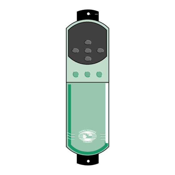
The parameters for a Control Techniques UNI2402 Unidrive Servo can be input using the on-board keypad, a remote keypad, or through UniSoft, a Windows-based configuration software tool. The drive has logically organized menus where parameters can be set.
To input parameters: 1. Use the keypad to navigate through the menus. 2. Select the required function from the logically organized menus. 3. Adjust the parameter values as needed. 4. Save the changes to apply the new settings.
For a Rover 346, specific motor and operational parameters should be set according to the motor’s requirements, such as speed limits, acceleration/deceleration times, braking mode, and PID control settings. If using UniSoft, connect the drive to a PC and configure it through the software interface.
This answer is automatically generated
Related Manuals for Control Techniques Unidrive Servo Series
drive overview Unidrive Servo & Unimotor The complete multi purpose Servo package with high flexibility & functionality Power Range 380-480V Size 1 - 0.75 to 4kW Size 2 - 5.5 to 11kW Size 3 - 15 to 37kW Size 4 - 45 to 110kW Size 5 - >110kW Line regeneration capability Motion Intelligence...
Page 5
drive overview Technology Many of these important product features would not be possible without the use of advanced technology in the Unidrive. The drive employs advanced microprocessor technology which controls all drive functions including input to the inverter ASIC (Application Specific Integrated Circuit) which synthesises an adjustable carrier frequency PWM (Pulse Width Modulation) output.
Page 6
drive overview Key Features Applications module High performance module General Features Ease of Use Features Coast & Ramp to Stop modes Macros 8 Preset speeds & Ramps Bright two line LED display 3 Skip frequencies Cloning module S Ramp Unisoft Motorised potentiometer Internal braking transistor as standard Maintenance Features...
introduction to macros Menu Overview Introduction Hard speed reference Encoder set up The Unidrive’s more than 700 parameters are Menu 4 Current monitoring organised so that similar parameters are grouped within Current limiting in speed control the same menu. For example, Menu 1 holds the Current loop gains parameters associated with the selection of a speed Torque control...
Page 8
introduction to macros Unidrive operation can be simplified by using pre- Menu 0 Parameter configured application macros. These macros are held in Param. Description the internal memory of the drive and are user selectable. 0.01 1.07 Minimum Speed 0.02 1.06 Maximum Speed Macro summary 0.03...
Page 9
introduction to macros Macro 4 – Torque control Macro 3 – Preset Speeds When this macro is selected a drive can be operated By using this macro up to four preset frequencies / in Speed or Torque control by using terminal 29. speeds can be used.
Page 10
introduction to macros Macro 5 – PID control Macro 6 – Axis Limit control This macro configures the drive to control a motor Using this macro enables two digital inputs to be with reference to PID control signal. In PID control, the re-programmed so providing limit switch lockout for error resulting from differences between the PID axis position control systems.
Page 11
introduction to macros Macro 7 – Brake control Macro 8 – Digital Lock This macro essentially allows the control of an The digital lock macro enables a drive to be external brake. The brake is released when the drive is operated so that it will lock two motor shafts together running and there is current in the motor.
drive technical specifications AC supply requirements Altitude 380V to 480V ±10%, 3-phase, 48 to 62 Hz Altitude range: 0 to 4000m (13000 ft), subject to the Maximum supply imbalance: 2% negative phase sequence following conditions: (equivalent to 3% voltage imbalance between phases) 1000m to 4000m (330 feet to 13000 ft) above sea level: de-rate the maximum output current from the specified Line reactors...
Page 13
drive technical specifications Dissipation Frequencies and Model Nominal Maximum total power dissipation speed rating @380V @460V 3kHz 4.5kHz 6kHz 9kHz 12kHz PWM switching UNI 1401 0.75kW 1.0HP 80 W 80 W 90 W 90 W 90 W frequency: UNI 1402 1.1kW 1.5HP 90 W...
Page 14
drive technical specifications Dynamic Braking Minimum Values Resistor Connections The calculated minimum ohmic value is limited by the braking transistor supplied in the Unidrive being The external braking resistor should be connected used. The following is a list of the minimum values. to the Unidrive terminals labelled (+) and (-) on the MODEL MINIMUM VALUE terminal strip on Unidrive size 1 &...
Page 15
drive technical specifications Protection DC Bus Undervoltage Trip 350 VDC DC Bus Overvoltage Trip 830 VDC MOV Voltage Transient Protection 160 Joules, 1400 Volts Clamping (Line to Line & Line to Ground) Drive Overload Trip Current overload value is exceeded. Programmable to allow up to 175% of Drive Current for one minute.
connections Control Inputs and Outputs TERMINAL I/O TYPE & FUNCTION RATING Status Relay 1 Normally open contacts Dry contact output pole 1/2 5A, 240 VAC resistive Drive OK (default) Status Relay 1 Dry contact output pole 2/2 Circuit Common 0 VDC Analogue reference +10 VDC ±...
Page 17
connections Typical power and default signal connections for speed control in terminal mode Status relay Optional Drive normal RFI filter Analog frequency/speed Signal reference 1 (remote) connector Connections for single-ended input Thermal signal protection device OV common Connections for differential input Start/ Stop signal...
drive installation Panel Wiring Guidelines for Routine EMC Precautions Optional braking resistors as required for the Drives External: Mount on top surface of enclosure. Internal: Mount in top part of enclosure. Location of overload protection device Drives Ensure minimum ³100mm ³5mm ³5mm clearances are...
Page 20
drive installation Surface Mounting Model Size Panel Dimension L F A [13.56] [13.56] [13.56] [28.19] 47.5 187.5 [1.88] [3.75] [7.38] [9.81] 16.5 16.5 [.63] [.63] [.63] [2.56] Panel 143.5 [5.63] L F A [14.25] [14.25] [14.25] [29.25] [3.75] [7.50] [14.75] [19.69] [7.88] [7.88]...
Page 21
drive installation Panel Through-panel Mounting Aperture Model Size Dimension 717.5 [13.56] [13.56] [13.56] [28.25] [11.63] [11.63] [11.31] [25.56] Panel 86.5 [3.38] [7.19] [14.13] [19] L F A Aperture (0.5) (0.5) [.63] [.63] [.25] [.31] [.13] Panel 16.5 Aperture [.13] L F A 131.5 [5.19] [7.56]...
Page 22
drive installation Motor cable Since capacitance in the motor cable causes loading on the output of the Drive, ensure the cable length does not exceed the values given in Table 2-3. Normal capacitance High capacitance Shield or armour Shield or armour separated from the cores close to the cores 480V...
Page 23
drive installation Enclosure Guidelines Insert the following values: Ti = 40°C Heat Dissipation in a Sealed Enclosure Tamb = 30°C 5.5 (typical for painted 2mm (.079in) If possible, locate heat-generating equipment in the sheet steel) lower part of the enclosure to encourage internal 100 at 3kHz (see pages 18 &19) convection.
electro magnetic compatibility (EMC) & radio frequency interference (RFI) Electromagnetic compatibility (EMC) conducted emission This is a summary of the EMC performance of the Drive. For full details, refer to the Unidrive EMC Data Sheet which can be obtained from a Drive Centre or distributor listed on the back cover.
electro magnetic compatibility (EMC) & radio frequency interference (RFI) RFI Filter Ratings Type Part number Power Ingress Max. ambient Case Max. dissipation at protection temperature at temperature rise continuous rated current rated current at rated current current 4200-0010 IP20 50°C (122°F) <30°C (86°F) 4200-0027 IP20...
Unimotor is a new range of brushless AC servo • Unique 'finned' design - high thermal dissipation motors from Control Techniques. They are three phase, • Encoder for high precision feedback integral 6 or 8 pole, permanent magnet motors exhibiting a commutation sinusoidal back EMF characteristic.
motor technical specification Specification Physical Environmental Insulation Class Class H, BS EN 60034-1. Ingress Protection Motor fitted with mating connector and cable: Dimensional Accuracy IEC 72-1, Class N (normal IP65. class), Class R (precision Speed up to 3000RPM: class) is optional. IP65.
Page 28
servo motor technical specification ∆T 100˚C, 40˚ Ambient with Encoder Feedback Motor Frame Size All Versions (rpm) Continuous Stall (Nm) Peak (Nm) 10.8 11.7 16.4 20.7 25.1 High (kgcm 2 ) Standard (kgcm 2 ) Weight(kg) Thermal Time Constant (sec) 1315 1431 1500...
motor installation Outline Drawings - Frame Sizes 75 - 142 Shaft Key Detail (REF) (MAX) (Option A) (MAX) SIGNAL CONNECTOR POWER CONNECTOR UNIMOTOR UM (REF) DANGER CAUTION High Voltage This machine runs hot UNIMOTOR UM (MAX) DO NOT USE COVER FOR LIFTING (REF) 4 HOLES DIA.
Page 33
motor installation Outline Drawings - Frame Size 190 A (MAX) Shaft Key Detail C (REF) B (MAX) (Option A) DIRECTION OF ROTATION FOR UVW= CLOCKWISE UNIMOTO 1 HOLE DRILL 34.0 DEEP & TAP M12 x 1.75 - 6H G1 (REF) G (REF) 4 HOLES x 28 DEEP...
Accessories Control Techniques offers a number of products, which add power, flexibility and value to the Unimotor range: Cable Assemblies and Connectors Control Techniques’ cable assemblies simplify motor connection and reduce installation time. Made to order in lengths up to 100 metres, they have a PUR sheath...
Page 35
• 4.0mm conductors are applicable to 190 frame sizes. connections of the motor to the drive. Control Techniques’ ready-made cables mean system installers can avoid the intricate, time consuming assembly normally associated with connecting servo systems. Installation and set-up time are greatly reduced - there is no fiddling with wire connections and crimp tools, and no fault finding.
Page 36
accessories PUR Power Cables Specification - Shielded Power Cable Options 2.5mm Cable Description (2.5mm ) PUR (2.5mm ) PUR Shielded Power, Shielded Power, without Brake with Brake Cable Type PSBA-- PBBA-- Power Conductors 4 x 2.5mm 4 x 2.5mm Brake Supply Wires 1 x (2x1) mm Conductor Type Copper stranded to DIN VDE 0295...
Page 37
accessories Specification - Shielded Power Cable Options 4.0 mm Cable Description (4.0 mm ) PUR (4.0 mm ) PUR Shielded Power, without Brake Shielded Power, with Brake Cable Type PSBB-- PBBB-- Power Conductors 4 x 4.0mm 4 x 4.0mm Brake Supply Wires 1 x (2x1) mm Conductor Type Copper stranded to DIN VDE...
Page 38
accessories Outline Drawing - Power Cable With Brake Power Cable Connections - with Brake Conductor Function ‘1’ Phase U Drive End Drive End ‘2’ Phase V Termination Identity Label Termination Earth 115.0 ±10 ‘3’ Phase W ‘5’ Brake ‘6’ Brake Brake CONNECTOR BODY Screen...
Page 39
accessories Signal Cable Specification - Shielded Signal Cable Incremental, PVC or PUR Cable Description PVC/PUR Shielded Signal - Incremental Cable Type SIAA-- Encoder Supply Conductors 1 x (2 x 1.0mm Conductor Type Tinned copper stranded to DIN VDE 0295 Class 5, IEC 228 Class 5 Insulation Material Polypropylene 1.75 mm dia.
Page 40
accessories Outline Drawing - Signal Incremental Cable Thermistor Wire Drive End Termination Connections 15 Pin D Type Connector Identity Label Connector Interconnection 165.0 ±10 Assembly Viewed from Viewed from rear Rear 16 17 Cable length: min.= 3.0 metres / max.= 100 metres Tolerance: -0.0 / +50mm ‘D’...
Page 41
UNIMOTOR Brushless Servo Motors Connector Accessories Control Techniques offers a range of connector accessories to suit the power and signal connection requirements of Unimotor UM and SL. Connector assembly kits, which include the power, signal connectors and their crimp sockets may be ordered, alternatively, individual connector assemblies may be ordered.
Page 45
torque speed curves & tables 142UME300 Unimotor 190UMC300 Unimotor UNI 4401 UNI 3405 UNI3401 UNI2403 Intermittent Torque Intermittent Torque 480 V 380 V UNI2403 UNI3401 380 V 480 V UNI 3405 UNI 4401 Continuous Torque Continuous Torque 1000 2000 3000 4000 5000 2000...
Page 46
torque speed curves & tables UNIMOTOR Brushless Servo Motors The time for which the stated overloads can be acheived will vary with the drive/motor combination used. Please consult technical manual for further details. UNIMOTOR/UNIDRIVE COMBINATION (12 kHz SWITCHING FREQUENCY ONLY) Unimotor Model 75UMA300 75UMB300...
servo sizing software CTSS (CT Sizing Software) is a new servo-sizing The components can be dragged from the toolbox into package developed to aid System Design Engineers in Workbench as required. Each has its own properties identifying the essential input parameters to correctly sheet, which describes the component, its size a servo application.
options UD70 Applications Module Easy to use, plug in, drives application module Low cost facility to develop application specific programs Advanced microprocessor technology providing the flexibility to develop complex applications Windows™ based Drive Programming Language ‘toolkit’ Bi-directional communications with full access to drive parameters Real-time calculations for complex time critical applications Embedded position controller...
Page 51
options UD70 Applications Module programs using the DPL Toolkit. Connection only requires a simple one-to-one ribbon cable to connect from a 9-pin PC serial port to the RS232 port. Features High speed read/write access (345 µs or 460 µs) to Task-based architecture allows easy implementation speed and torque reference within the drive.
typical applications Pick and Place Gantry Control Unidrives Objective: Utilise standard products with easy Unimotor Unimotor programming for point-to-point position control Solution: Unidrive with MC204 controller Operation: MC204 moves all three axes from 3-D position MC Series to 3-D position co-ordinates quickly and accutately.
Page 55
typical applications Constant Controller Maintains Constant Gap Objective: Provide desired “Tail to Head” spacing. Unidrive with UD70 Regardless of product length. Product Solution: Unidrive with UD70 applications module. Measuring Photoeye Operation: Photocells trigger the PCM-19 to monitor Sync Encoder encoder input for product position, length and Unimotor height.
Page 56
typical applications Flying Cut Off - Inline Unidrive with UD70 CTIU Objective: Provide an easy method for an operator to Unimotor Operator Interface Motion SCS-X enter product cut lengths Encoder Solution: Unidrive with UD70 motion profiler and CTIU Motion operator interface. Operation: When the correct product length passes, the cut bar is accelerated to match the speed of Velocity...
Need help?
Do you have a question about the Unidrive Servo Series and is the answer not in the manual?
Questions and answers
Need to input parameters into a UNI2402 Unidrive for a Rover 346
Need to input parameters into a UNI2402 Unidrive for a Rover 346 To clarify, it is a Biesse Rover 346... a c&c Machine Thanks
The parameters for a Control Techniques UNI2402 Unidrive Servo can be input using the on-board keypad, a remote keypad, or through UniSoft, a Windows-based configuration software tool. The drive has logically organized menus where parameters can be set.
To input parameters:
1. Use the keypad to navigate through the menus.
2. Select the required function from the logically organized menus.
3. Adjust the parameter values as needed.
4. Save the changes to apply the new settings.
For a Rover 346, specific motor and operational parameters should be set according to the motor’s requirements, such as speed limits, acceleration/deceleration times, braking mode, and PID control settings. If using UniSoft, connect the drive to a PC and configure it through the software interface.
This answer is automatically generated