
Related Manuals for Control Techniques Emerson Focus 1


Summary of Contents for Control Techniques Emerson Focus 1
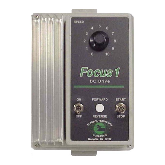
- Page 1 Focus 1 ¼ to 2HP Single Phase, Uni-Directional Non-Regenerative DC Drive User Guide P/N: FOCUS1-UG Revision: A1 Date: Feb 10, 2005 © Control Techniques Drives, Inc. 2005 Page i...
- Page 2 User Guide, without notice. All rights reserved. No parts of this User Guide may be reproduced or transmitted in any form or by any means, electrical or mechanical, without permission in writing from Control Techniques. Page ii...
- Page 3 Whether it’s by phone, fax or modem, you can access Control Techniques support information 24 hours a day, seven days a week. Our wide range of services include: (716) 774-8327 You can FAX questions and comments to Control Techniques Just send a FAX to the number listed above. Website and Email www.emersonct.com...
- Page 4 “Warning” indicates a potentially hazardous situation that, if not avoided, could result in death or serious injury. “Caution” indicates a potentially hazardous situation that, if not avoided, may result in minor or moderate injury. “Caution” used without the safety alert symbol indicates a potentially hazardous situation that, if not avoided, may result in property damage.
- Page 5 Safety Considerations Safety Precautions This product is intended for professional incorporation into a complete system. If you install the product incorrectly, it may present a safety hazard. The product and system may use high voltages and currents, carry a high level of stored electrical energy, or are used to control mechanical equipment that can cause injury.
- Page 6 General warning Failure to follow safe installation guidelines can cause death or serious injury. The voltages used in this unit can cause severe electric shock and/or burns, and could be lethal. Extreme care is necessary at all times when working with or adjacent to this equipment.
-
Page 7: Table Of Contents
Table of Contents Topic Page Introduction Motor Compatibility Basic Control Modes/Feedback Armature Voltage Feedback Quick Stops Receiving, Inspection, Storing Performance Features Nameplate Information Nameplate Location Catalog Number Definition Specifications Ratings Table Performance Specifications Operating Conditions Internal Adjustments (Potentiometer) Customer Selections (Jumpers) Operator Functions Control Circuit Specifications Options... - Page 8 Table of Contents Topic Page Power Wiring Control Wiring 29-31 Speed Pot Wiring Customer Selections Jumper Programming 34-38 Current Ranges Current/Torque Control 36,48 LED Status Indicator Potentiometer Adjustments 38-40 38-39 Basic Adjustments Tuning Adjustments Interconnect Drawings Functional Block Diagram Circuit Overview Start-up Guide Worksheet 41-43 Application Safety...
-
Page 9: Introduction
Introduction This is the User’s Guide for Focus 1 (Non-regenerative) series of DC Drives. The Focus 1 is a 2nd generation product of the long-standing Focus series. The Focus 1 was introduced back in 1980. The Focus 1 non-regen drive remains as a popular single-phase, uni-directional analog drive for DC motors with power ranges from ¼... -
Page 10: Motor Compatibility
1 requires 240vac input power and must be internally set for this input level. The motor field resistance should not be less than 150 ohms when cold and will require a series resistor to drop the additional field supply voltage. Consult Control Techniques Technical Support for additional information. - Page 11 Motor Compatibility Motors with: Permanent Magnet Motors typically have only 2 power wires. These are the Armature leads and typically designated A1 and A2 or A+ and A-. The Focus 1 is compatible with most all PM motors having either 90v or 180v armatures. Armature Armature Voltage...
-
Page 12: Armature Voltage Feedback
Speed Control Armature Voltage Feedback The Focus 1 varies the speed of the motors mentioned above as a function of the Speed potentiometer setting (or external speed command signal) by simply varying the output Armature voltage (field excitation if used typically remains constant). Armature Voltage Feedback (or simply Armature Feedback) does not require any special motor mounted speed feedback device and is therefore inherently quite reliable and is capable of providing up to 1% speed regulation. - Page 13 General Information Introduction The purpose of this manual is to provide the user with the information needed to install, start-up, and maintain the Focus 1 drive. This instruction manual should be read in its entirety, paying special attention to the warning and caution notices, before installation and before performing any start-up or drive maintenance.
-
Page 14: Performance Features
PERFORMANCE FEATURES • Solid State Full Wave Power Bridge -Uses generously rated power semiconductors for Maximum reliability and long life. • Inner Current Loop Regulator - Inherent high bandwidth capability for fast response. • Fusing - Both AC lines fused for maximum protection in case of short circuit. •... -
Page 15: Nameplate Information
The Focus 1 comes in two basic model variations- with and without enclosure. Chassis Model The model without an enclosure is denoted as a chassis model. The chassis model is intended for mounting within a User supplied cabinet and where the User intends to provide remote Start/Stop and Speed control signals. -
Page 16: Specifications
Specifications Ratings AC Input Output Catalog Enclosure 1Ø Armature Field Field Armature Part # Volts Amps Volts Amps Volts Amps 2400- Chassis ¼ -1 8001W ½-2 2400- NEMA 1 ¼ -1 8000W ½-2 Page 16... -
Page 17: Performance Specifications
PERFORMANCE SPECIFICATIONS Service Factor Speed Regulation (95% Load Change): Armature Voltage 1% of Max. Speed with IR Compensation All other variables (voltage regulated) 15% of Base Speed Speed Range: 30:1 Efficiency: Control Only Drive System (motor and control) 86% typically DRIVE OPERATING CONDITIONS Altitude (without derating) 3300Feet or 1000meters... -
Page 18: Operator Functions
OPERATOR FUNCTIONS Chassis Enclosed Speed Adjustment (Speed Pot) Standard Standard Start/Stop Customer Supplied Standard Forward/Reverse Optional Optional CONTROL CIRCUIT SPECIFICATIONS Logic Control Power 24 Vdc Speed Potentiometer 5000 ohms Input Signal Requirement 10 Vdc @ 0.2mA (44Kohm input resistance) Control Circuit Isolation Optional FOCUS 1 OPTIONS CATALOG... -
Page 19: Dimensions
Focus 1 Chassis Dimensions Chassis Suitable for mounting in a user’s enclosure where internal temperatures will not exceed C or 130 2400-8001W Page 19... - Page 20 Focus 1 Enclosed Dimensions NEMA 1 Suitable for most well ventilated factory areas where industrial equipment is installed. Locations subject to steam vapors, oil vapors, flammable or combustible vapors, chemical fumes, and corrosive gases or liquids should be avoided unless an appropriate enclosure has been supplied.
- Page 21 Focus 1 Option Kits Focus 1 Contactor Kit – P/N 2400-9001 This Kit includes a magnetic contactor that can be mounted either in the Focus 1 enclosed unit or on the chassis mount unit. It provides a positive disconnect of the motor armature when the controller is stopped, preventing motor rotation in the event of SCR mis-fire due to line noise.
- Page 22 Focus 1 Option Kits Focus 1 Nema 4/12 Kit– P/N 2400-900 This Kit is used to convert the standard Nema 1 enclosure to a Nema 4/12 rating suitable for “wash down” environments. Included in the kit is a gasket to seal the connection between the upper and lower enclosure sections, three boot seals for the switches for the Start / Stop, AC power On/Off and optional Fwd / Rev switches, and a shaft-sealing not for...
- Page 23 Focus Family Options Speed Remote Operator Station – P/N 2950-9068 /2950-9066 Speed These NEMA 1 operator stations can be used to remotely control Focus 1 Motor Controllers. Two models are available as shown. Both units include a Speed Potentiometer, a Start green normally open start button and a red normally closed Auto...
- Page 24 Speed Potentiometer – P/N SpdPot This potentiometer can be used for either a remote speed command potentiometer remote current limit potentiometer. The following kits are available for the Focus series of drives. They are designed to provide a 120-Vac interface for applications requiring remotely mounted industrial operator devices (i.e.
-
Page 25: Customer Connections & Start-Up
Customer Connections & Start-Up NOTE Read this manual in its entirety, paying particular attention to the Warnings and Cautions in each section before installing, starting, or maintaining this drive. Improper procedures can result in personal injury or equipment damage. Only qualified electrical maintenance technicians familiar with electronic drives and their standard safety precautions should be permitted to install, start-up, or maintain this apparatus. - Page 26 Incoming Power Requirements A remote fused AC line disconnects or circuit breaker installed ahead of the control is required by the NEC (National Electrical Code). The control is designed to accept single-phase AC line voltage. Grounding The control must be connected to earth ground either via mounting screws provided by an enclosure or chassis-installed screw or by using the Earth Ground lug provided on the drive heatsink, for safety of operating personnel.
- Page 27 Motor Thermal Switch For Motor Thermostat wiring, see the “Control Wiring” section. Wrong Motor Rotation If the motor rotates in the wrong direction, one of the following changes will correct it: Only With Power Removed Exchange Al and A2 output Motor Armature leads. Exchange Fl and F2 Motor Shunt field leads.
- Page 28 Drive Power Wiring Focus 1 Models AC Line Input Earth Connection A+ & A- are the motor Armature leads F+ & F- are a shunt wound motors Field leads ( they will not be present on Permanent Magnet or Universal Motors ) Page 28...
-
Page 29: Control Wiring
Control Wiring TERMINAL CONNECTIONS (TB2) & DESCRIPTIONS Pin Number Forward: Connected to “quick connect” 1 as a tie point for the Motor Reversing Contactor Kit forward / reverse switch, or the motor contactor Reverse: Connected to “quick connect” 1 as a tie point for the Motor Reversing Contactor Kit forward / reverse switch. - Page 30 Page 30...
- Page 31 Terminal Strip Connections Enclosed Model Standard Start / Stop & Speed Potentiometer Connections The Start/Stop Switch And the Speed Stop Start Potentiometer are supplied as shown on the drive cover Drive will not start without this. This is intended for system interlock- see Application Safety Speed...
- Page 32 Chassis Model The Chassis Model has no operator devices connected to the drive control terminal strip. The only connections made are connections from terminal #3 to #4 which is required for three wire Start/Stop controls. The Speed Potentiometer is supplied “loose” with the drive. Stop Start Stop...
-
Page 33: Speed Pot Wiring
CCW=counter clockwise Cable should be 3 conductor with overall shield w/pot end tied off and dressed. Cable and pots are available from: Control Techniques Service Center @ 1-800-367-8067 Cable P/N 3CONCBL-XXX (XXX in feet) Speed Potentiometer P/N SpdPot Do Not Connect shield to Earth. This will result in permanent damage... -
Page 34: Customer Selections
Customer Jumper Selections Jumper Programming Equipment damage and/or personal injury may result if jumper programming is attempted while control is operational. Always lock out power at the remote disconnect before changing jumper positions. See page 33 for jumper locations JUMPER DESCRIPTION RANGE FACTORY SETTING Speed or Current Control... - Page 35 Input Voltage Selection Input Line Voltage Jumper Positions 120Vac A to E B to D 240Vac A to C B to C Items in BOLD are factory set positions This photo shows the drive settings for 115vac operation Caution Application of 240vac to a unit set up for 115vac ( as shown above ) will damage the drive and void the warranty.
- Page 36 Current Feedback Range (J2) For 115vac Operation on 90vdc motors Motor HP DC Output Current Range (Amps) Jumper Position For 230vac Operation on 180vdc motors Motor HP DC Output Current Range (Amps) Jumper Position 1-1/2 J2 -- Max Output Current Select based on motor Armature requirements Page 36...
- Page 37 Current Control Mode Focus 1 Drives can be configured to operate in the Current Control Mode which is often referred to as making the drive a “Current Regulator”. Since motor torque is directly proportional to the armature current, a drive configured as a Current Regulator is often referred to as a “Torque Regulator”.
-
Page 38: Led Status Indicator
LED Status Indicators – This red led will illuminate any time the run relay is energised Page 38... -
Page 39: Basic Adjustments
Basic Customer Adjustments Maximum Speed (MAX SPD) The MAX SPD pot sets the maximum motor speed (80-120% of motor base speed) allowed. It is factory preset to the midway position. Note: Do not exceed motor nameplate maximum speed rating. With the motor running, turn the speed pot on the drive enclosure cover/operator control panel fully clockwise while monitoring actual motor RPM or by measuring the Armature Voltage on A+ &... - Page 40 Basic Customer Adjustments MIN SPD Adjust for minimum Motor speed MAX SPD Adjust for maximum Motor speed Page 40...
-
Page 41: Tuning Adjustments
Additional Tuning Adjustments Internal Resistance Compensation ( IR COMP ) Compensation pot is used to overcome the motor’s natural tendency to slow down as the load increases. If the motor slows down excessively as it is loaded, adjust the IR COMP pot clockwise to recover speed lost during the loaded condition. The motor will oscillate in speed or “hunt”... -
Page 42: Start-Up Guide Worksheet
Start-up Guide Worksheet Improper procedures can result in personal injury or equipment damage. Only qualified electrical maintenance technicians familiar with electronic drives and their standard safety precautions should be permitted to install, start-up, or maintain this apparatus. At this point all INPUT POWER must be OFF ! Obtain the following information: Focus Drive Model 2400-8000... - Page 43 Focus 1 Jumper Setup Worksheet Refer to the data recorded on the previous page for this worksheet Refer to your motor nameplate data. STEP 1 Does your motor have a shunt field winding? If No go to STEP 5 otherwise go on. STEP 2 Is your motor field current greater than 1.1A? If No, go to STEP 3...
- Page 44 Armature Current Programming - (J2) Current Feedback Range STEP 7 Set jumper J2 to the range that matches up most closely with your motors Armature Amp rating from the table below: FOCUS Catalog DC Output Current Number Jumper Position 2400-8000 2400-8001 When making any wiring or jumper changes, the incoming AC power must be turned off and locked out.
-
Page 45: Application Safety
Application Safety When applying a motor drive in a manufacturing process, one must understand that the motor drive merely provides the energy for a motor to turn and it will do so without regard upon activation and command. There could be failure modes in any external interface equipment and/or the Focus drive itself that could cause the motor to turn suddenly at any speed or cause it to fail to stop on command without warning. -
Page 46: System Interface Suggestions
System Interface Suggestion A fundamental basic system interface suggestion would be to always employ a method to supply a “permissive” or System Enable to allow the drive system to work if all things on the machine are alright. This interface would provide a method to keep the System disabled if certain key safety permissives are not satisfied. -
Page 47: Installation Of Option Kits
Initial Start-Up The following procedure is to verify proper operation of the drive in its simplest form as a basic speed regulator with no option kits installed. It is assumed that the drive is in its “out of box” condition with respect to jumper programming with the exception of what was just changed in the previous pages, jumper setup worksheet. - Page 48 Initial Start-Up con’t A minimal number of connections are made to the terminal strip (see diagrams below). If the drive is an enclosed unit with operator devices (start/stop and speed pot) only the jumper from terminal block TB2-5 to TB2-5A needs to be made- this is a temporary connection only intended for System Interlock - Application Safety Regulation Mode: In this procedure, leave jumper in speed regulation...
- Page 49 Initial Start-Up con’t 1. Adjust Speed pot (enclosed unit) approximately 1/3 turn clockwise (from full CCW position) Power can now be Applied ! 2. Start drive. Run light (red) should be illuminated. 3. Slowly adjust Speed pot clockwise (~1/4 turn) while watching motor shaft. Verify that the motor rotates in the desired direction and that the motor slowly accelerates to about 30% of rated speed.
-
Page 50: Trouble Shooting Guide
Focus 1 Trouble Shooting Guide IMPORTANT SAFEGUARDS All work on the drive should be performed by personnel familiar with it and its application. Before performing any maintenance or troubleshooting, read the instructions and consult the system diagrams. Only minor adjustments should be necessary on initial start-up, depending on the application. - Page 51 TROUBLESHOOTING OVERVIEW Fast and effective troubleshooting requires well-trained personnel supplied with the necessary test instruments as well as a sufficient stock of recommended spare parts. Capable electronic technicians who have received training in the control operation and who are familiar with the application are well qualified to service this equipment. Suggested Training A.
-
Page 52: Oscilloscope Safety
Oscilloscope Safety There are instances where a simple digital multimeter is not sufficient to trouble shoot a DC Drive and an oscilloscope must be used. This note will explain how to properly connect to the drive. Focus 1, Focus 2 and Focus 3N non-regenerative drives are known as “hot “ chassis type drives. - Page 53 Typical Line Power Oscilloscope 1. One could use a small isolation transformer to power the scope, this will effectively eliminate the earth ground connection. Earth Ground Pin Is Tied internally to ground clip on probe Page 53...
- Page 54 Portable Battery Powered Oscilloscope Use of a battery powered oscilloscope without an AC/DC adapter is the best method to observe drive waveforms. When using a dual channel oscilloscope make sure that you use only 1 scope ground lead – remove the scope ground lead on the other probe. For AC Line Powered Oscilloscopes Preferred Method- Differential Channel Method 1.
- Page 55 NOTE: When the following methods #2 and #3 are used, the case/chassis of the scope will be floating above ground at what ever the voltage level the drive is at with respect to earth ground. This could be as high as 250vac for a Focus drive. Care must be taken as not to touch the case and earth ground, a severe electrical shock can occur which could be life threatening.
- Page 56 BASIC TROUBLESHOOTING This paragraph contains a basic list of symptoms of an improperly functioning control. Included in the list are possible causes and corrective measures for each symptom described. BEFORE PROCEEDING WITH ANY MAINTENANCE OR TROUBLE-SHOOTING ACTIVITY, ALL POWER SOURCES MUST BE DISCONNECTED. CONTROL APPEARS TO BE DEAD Terminals TB2-5 and –5A on the main PC board not jumpered together - install either a jumper or the Motor Thermostat between these terminals.
- Page 57 MOTOR RUNS IN WRONG DIRECTION: A. The Al and A2 output leads to the motor are incorrectly wired - exchange these leads. B. On shunt wound motors only the shunt field Fl and F2 leads are incorrectly wired – exchange these leads. MOTOR DOES NOT MAINTAIN SPEED UNDER LOAD: A.
-
Page 58: Light Bulb Test
Basic Test Setup – Light Bulb Test It is fairly easy to test Focus Drives on the bench. One does not have to use a motor to verify basic operation. When working properly, the Focus basically creates a variable voltage much like a light dimmer except the output is DC. The easiest way to check a Focus on the bench without a motor is to connect the Armature output to a resistive load. - Page 59 Record Drive Set-up BEFORE performing Light bulb test Before Test Test Circle One SPD CUR ARM TACH Med Low 115 Vac 230 Vac 115 Vac Operation Operation Basic Armature Circuitry Checkout After the Focus is wired as shown on the previous page and the jumper set as indicated above, 115 Vac power could be applied and the Focus should cause the light bulb to vary in brightness from nothing to full brightness.
-
Page 60: Application Notes
Application Notes In order to provide continuing support for the Focus products (as well as all of our other products): ( if this is being viewed electronically, click on any blue item for link ) Application Notes (CTANXXX) Technical Notes (CTTNXXX) Replacement Instructions (CTRIXXX) - Page 61 CTAN #215 Ways of Achieving Isolation Non-Regenerative DC Drives Focus non-regenerative motor controllers are not isolated from the power circuit. Essentially, circuit common on the control card is connected directly to the A+ terminal of the motor. Therefore, NO terminal connection on the control terminal strip (TB2) can be connected to earth ground in any way, even momentarily.
- Page 62 Solutions to Applications Requiring Control Inputs to be Earth Grounded Solution #1 – Focus 3 Signal Isolator Board Focus Terminal Strip Stop Speed Or signal from a PLC or computer DCS system where F3NSBD isolation is unknown or must be maintained This option is used in applications where isolation is required between an external control signal and the motor controller (which may or may not be at earth ground...
- Page 63 Solution #2 – Isolation Transformer Focus 1 DC Motor Controller DO NOT CONNECT GROUND TO TRANSFORMER SECONDARY Transformer KVA = 1.5 x Rated Armature Current x 120 Vac (or 240) Example: Your DC Motor has a 10 A armature KVA = 1.5 x 10 A x 120 Vac = 2.4 KVA (use 2.5 KVA) Page 63...
- Page 64 Critical Components and Replacement Parts Main Control Board This control board is used on both the all Focus 1 models: Replacement Instructions for Control Board (CTRI219) can be found at our website at: www.emersonct.com or click the link below: CTRI219 2400-4100 Speed Adjust Pot Switches...
- Page 65 INDEX Jumpers · 8, 25, 33, 34, 35, 42, 43 Adjustments · 7, 8, 25, 39, 40 Current Limit · 14, 17 Kits IR Comp · 17 Installation · 7, 8, 18, 21, 22, 27, 46 Tuning · 8, 40 Option Kits ·...
- Page 66 Spare Parts · 8 Terminals · 30, 55, 56 Critical Components · 55, 56, 63 Torque Control · 8, 14, 17, 36, 41, 48 Specifications · 7, 16 Troubleshooting · 50 Speed Control Armature Voltage Feedback · 7, 12 Speed Pot · 8, 18, 30 Start-Up ·...
Need help?
Do you have a question about the Emerson Focus 1 and is the answer not in the manual?
Questions and answers