
Related Manuals for Control Techniques Commander SK


Summary of Contents for Control Techniques Commander SK
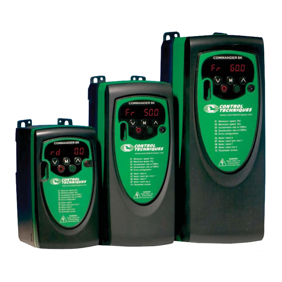
- Page 1 Getting Started Guide Commander SK AC variable speed drive for 3 phase induction motors from 0.25kW to 4kW, 0.33hp to 5hp Model sizes A, B and C Part Number: 0472-0000-01 Issue: 1...
- Page 2 These differences may cause the product to function differently. This may also apply to drives returned from the Control Techniques Service Centre.
-
Page 3: Table Of Contents
Keypad control ..................37 Diagnostics and Protective Features ......39 Options ................41 SmartStick: Parameter cloning module ..........42 Documentation ..................42 Parameter List ..............43 UL Listing Information ............. 45 Commander SK Getting Started Guide Issue Number: 1 www.controltechniques.com... -
Page 4: Safety Information
Environmental Limits Instructions within the supplied data and information within the Commander SK Product Data Guide regarding transport, storage, installation and the use of the drive must be complied with, including the specified environmental limits. Drives must not be subjected to excessive physical force. -
Page 5: Compliance And Regulations
1.8.3 STOP function The STOP function does not remove dangerous voltages from the drive, the motor or any external option units. Commander SK Getting Started Guide Issue Number: 1 www.controltechniques.com... - Page 6 If the drive has failed in a manner that causes the display to go blank immediately, it is possible the capacitors will not be discharged. In this case, consult Control Techniques or their authorised distributor.
-
Page 7: Rating Data
The maximum continuous current inputs are used to calculate input cable and fuse NOTE sizing. Where no maximum continuous input currents are indicated, use the typical full load input current values. See Commander SK Product Data Guide for cable and fuse data. Commander SK Getting Started Guide Issue Number: 1 www.controltechniques.com... -
Page 8: Mechanical Installation
Installation Installation and Display Commissioning List Information Mechanical Installation Figure 3-1 Commander SK dimensions Mounting holes: 4 x M4 holes Table 3-1 Commander SK dimensions Drive size 140 5.51 154 6.06 2.09 26.5 1.04 26.5 1.04 2.95 145 5.71 143 5.63 86.3 3.40 190 7.48 205 8.07... - Page 9 Safety Rating Mechanical Electrical Keypad Quick Start Parameter UL Listing Parameters Diagnostics Options Information Data Installation Installation and Display Commissioning List Information Figure 3-2 Minimum mounting clearances Commander SK Getting Started Guide Issue Number: 1 www.controltechniques.com...
-
Page 10: Electrical Installation
*For further information, see section 4.3 Internal EMC filter on page 12. Fuses/MCB The AC supply to the drive must be fitted with suitable protection against overload and short circuits. Failure to observe this requirement will cause risk of fire. WARNING Commander SK Getting Started Guide www.controltechniques.com Issue Number: 1... -
Page 11: Ground Leakage
Type B - detects AC, pulsating DC and smooth DC fault currents • Type AC should never be used with drives • Type A can only be used with single phase drives • Type B must be used with three phase drives Commander SK Getting Started Guide Issue Number: 1 www.controltechniques.com... -
Page 12: Internal Emc Filter
Tab fully extended: EMC filter disconnected A full range of external EMC filters is also available for use with Commander SK in installations where EMC requirements are stringent. These, along with the correct wiring practice, prevent the drive from causing interference with susceptible electrical equipment. -
Page 13: I/O Specification
Operation of contact CLOSED AC supply applied to drive with drive in a 'ready to run' or 'running' condition (not tripped) Provide fuse or other over-current protection in status relay circuit. WARNING Commander SK Getting Started Guide Issue Number: 1 www.controltechniques.com... - Page 14 If the enable and run forward or enable and run reverse terminals are closed when the drive is powered up, the drive will run straight away up to a set speed. Commander SK Getting Started Guide www.controltechniques.com Issue Number: 1...
-
Page 15: Keypad And Display
START key is used to start the drive in keypad mode. STOP/RESET key is used to stop and reset the drive in keypad mode. It can also be used to reset the drive in terminal mode. Commander SK Getting Started Guide Issue Number: 1 www.controltechniques.com... -
Page 16: Selecting And Changing Parameters
MODE key is pressed, pressing the MODE key will change the display to the parameter edit mode again. This allows the user to very easily change between parameter view and edit modes whilst commissioning the drive. Commander SK Getting Started Guide www.controltechniques.com Issue Number: 1... -
Page 17: Saving Parameters
The setting of the user security Pr 25 determines whether the parameter access is read only (RO) or read write (RW). Table 5-1 Parameter access (Pr 10) Parameters accessible Pr 01 to Pr 10 Pr 01 to Pr 60 Pr 01 to Pr 95 Commander SK Getting Started Guide Issue Number: 1 www.controltechniques.com... -
Page 18: Security Codes
Unlock security as described above. • Set Pr 25 to 0 • Press the MODE key. If a security code has been lost or forgotten, please contact your local drive centre or NOTE distributor Commander SK Getting Started Guide www.controltechniques.com Issue Number: 1... - Page 19 Set Pr 29 to EUR and press the Stop/Reset key. This loads 50Hz default parameters. • Set Pr 29 to USA and press the Stop/Reset key. This loads 60Hz default parameters. Commander SK Getting Started Guide Issue Number: 1 www.controltechniques.com...
-
Page 20: Parameters
If one of the standard ramp modes is selected (see Pr 30 on page 27), the deceleration NOTE rate could be extended automatically by the drive to prevent over voltage (OU) trips if the load inertia is too high for the programmed deceleration rate. Commander SK Getting Started Guide www.controltechniques.com Issue Number: 1... - Page 21 Run Forward Run Forward (USA: Run) (USA: Run) Run Reverse Run Reverse (USA: Jog) (USA: Jog) Local (A2)/Remote (A1) Reference select speed reference select Reference selected Preset 2 Preset 3 Preset 4 Commander SK Getting Started Guide Issue Number: 1 www.controltechniques.com...
- Page 22 When Pr 05 is set to E.Pot, the following parameters are made available for adjustment: • Pr 61: Motorised pot up/down rate (s/100%) • Pr 62: Motorised pot bipolar select (0 = unipolar, 1 = bipolar) Commander SK Getting Started Guide www.controltechniques.com Issue Number: 1...
- Page 23 Figure 6-9 PID logic diagram Drive reference PID reference P Gain input % to frequency I Gain conversion Invert PID high limit PID feedback PID low limit input x(-1) PID enable & Drive healthy Commander SK Getting Started Guide Issue Number: 1 www.controltechniques.com...
- Page 24 If the motor is not a standard 50 or 60Hz motor, see Pr 39 on page 30 and adjust accordingly. NOTE Function Range Defaults Type Motor power factor 0 to 1 0.85 Enter the motor rated power factor cos ϕ (taken from the motor name plate). Commander SK Getting Started Guide www.controltechniques.com Issue Number: 1...
-
Page 25: Parameter Descriptions - Level 2
The output not programmed to the brake control can be programmed to indicate the required signal. (See Commander SK Advanced User Guide.) A change to Pr 12 is set by pressing the MODE key on exit from parameter edit mode. - Page 26 Cd: Machine speed in customer defined units (See Pr 24). Function Range Defaults Type Customer defined scaling 0 to 9.999 1.000 Multiplying factor on motor speed (rpm) to give customer defined units. Commander SK Getting Started Guide www.controltechniques.com Issue Number: 1...
- Page 27 Fast ramp is linear deceleration at programmed rate, normally used when a braking resistor is fitted. Standard ramp is controlled deceleration to prevent DC bus over-voltage trips, normally used when there is no braking resistor fitted. Commander SK Getting Started Guide Issue Number: 1 www.controltechniques.com...
- Page 28 Fr, Fr.hr dig: Digital input Motor thermistor input, connect as per diagram below Frequency input. See Commander SK Advanced User Guide. Fr.hr: High resolution frequency input. See Commander SK Advanced User Guide. Figure 6-11 Motor thermistor input Trip resistance: 3kΩ...
- Page 29 A change to this parameter is only implemented if the drive is disabled, stopped or NOTE tripped and the STOP/RESET key is pressed for 1s. See the Commander SK Advanced User Guide. Function Range Defaults Type...
- Page 30 0 to 247 Defines the unique address for the drive for the serial interface. Function Range Defaults Type Software version 1.00 to 99.99 Indicates the version of software fitted to the drive. Commander SK Getting Started Guide www.controltechniques.com Issue Number: 1...
- Page 31 The ramp is held during this time. Function Range Defaults Type Post brake release delay 0.0 to 25.0 s Defines the time between the brake being released and the ramp hold being released. Commander SK Getting Started Guide Issue Number: 1 www.controltechniques.com...
- Page 32 0 to 255 Function Range Defaults Type Fieldbus baud rate 0 to 8 Function Range Defaults Type Fieldbus diagnostics -128 to +127 See the appropriate fieldbus option module manual for further information. Commander SK Getting Started Guide www.controltechniques.com Issue Number: 1...
-
Page 33: Parameter Descriptions - Level 3
Pr 1.29 where it can be adjusted. Some parameters are only implemented if the drive is disabled, stopped or tripped and NOTE STOP/RESET key is pressed for 1s. See Commander SK Advanced User Guide for advanced parameter details. Parameter descriptions - Level 3 Function Range... -
Page 34: Diagnostic Parameters
OFF (0) or On (1) Reverse selected indicator OFF (0) or On (1) Jog selected indicator OFF (0) or On (1) Analog input 1 0 to 100 % Analog input 2 0 to 100 % Commander SK Getting Started Guide www.controltechniques.com Issue Number: 1... -
Page 35: Quick Start Commissioning
+24V output +24V output Digital output Digital output (zero speed) (zero speed) Drive Enable/Reset Not Stop Run Forward Run Reverse Local (A2)/Remote (A1) Local (A2)/Remote (A1) speed reference select speed reference select Commander SK Getting Started Guide Issue Number: 1 www.controltechniques.com... - Page 36 • The Enable and Run Forward or Run Reverse signals The Commander SK will carry out a non-rotating autotune on the motor. The display will flash alternatively between 'Auto' and tunE' to show that an autotune is being carried out on ∅...
-
Page 37: Keypad Control
Not used Analog output (motor speed) +24V output Digital output (zero speed) Drive Enable/Reset Forward/Reverse Not used Not used To implement a Forward/Reverse switch, see the Commander SK Advanced User Guide. NOTE Commander SK Getting Started Guide Issue Number: 1 www.controltechniques.com... - Page 38 Press the DOWN key to decrease the speed Stopping Press the STOP/RESET key to stop the motor To implement a Forward/Reverse switch, see the Commander SK Advanced User Guide. NOTE Commander SK Getting Started Guide www.controltechniques.com Issue Number: 1...
-
Page 39: Diagnostics And Protective Features
SmartStick/drive rating change rating O.cL Overload on current loop input Input current exceeds 25mA Internal drive hardware fault (see Commander SK Advanced HFxx trip Hardware faults User Guide) * The Enable/Reset terminal will not reset an O.Ld1 trip. Use the Stop/Reset key. - Page 40 75°C, the heatsink fan will remain off, if the heatsink temperature rises above 75°C, the heatsink fan will switch on until the heatsink temperature falls below 65°C. For further details, see the Commander SK Advanced User Guide. Commander SK Getting Started Guide www.controltechniques.com...
-
Page 41: Options
To reduce supply harmonics Windows based set-up software for advanced CT Soft programming * Only applicable to sizes B and C Details of all the above options can be found at www.controltechniques.com. Commander SK Getting Started Guide Issue Number: 1 www.controltechniques.com... -
Page 42: Smartstick: Parameter Cloning Module
See Pr 28 on page 27 for details. Figure 9-1 Location of SmartStick Documentation As well as the Commander SK Getting Started Guide, a number of other guides are available for Commander SK: Commander SK Product Data Guide This gives all the technical data for the drive, such as: •... -
Page 43: Parameter List
Brake applied current threshold (%) Brake release frequency (Hz) Brake applied frequency (Hz) Pre-brake release delay (s) Post brake release delay (s) Fieldbus node address Fieldbus baude rate Fieldbus diagnostics Last trip Commander SK Getting Started Guide Issue Number: 1 www.controltechniques.com... - Page 44 Pr 63 set-up parameter Pr 64 set-up parameter Pr 65 set-up parameter Pr 66 set-up parameter Pr 67 set-up parameter Pr 68 set-up parameter Pr 69 set-up parameter Pr 70 set-up parameter Commander SK Getting Started Guide www.controltechniques.com Issue Number: 1...
-
Page 45: Ul Listing Information
Safety Rating Mechanical Electrical Keypad Quick Start Parameter UL Listing Parameters Diagnostics Options Information Data Installation Installation and Display Commissioning List Information UL Listing Information Commander SK Getting Started Guide Issue Number: 1 www.controltechniques.com... - Page 46 T1 T2 T3 T4 T5 T6 B1 B2 B3 B4 B5 B6 Pr 29 = Eur Remote speed Remote current speed reference input reference input (A1) +10V reference output Local voltage speed reference input (A2) (2kmin) Fault Analog output (motor speed) +24V output +24V Digital output...
Need help?
Do you have a question about the Commander SK and is the answer not in the manual?
Questions and answers