Table of Contents
Advertisement
Advertisement
Table of Contents

Related Manuals for Mitsubishi 700 Series


Summary of Contents for Mitsubishi 700 Series
- Page 1 INVERTER PRE-OPERATION INSTRUCTIONS Plug-in option A7NETH-2P INSTALLATION INSTRUCTION MANUAL INVERTER SETTINGS REGISTER NUMBERING Ethernet multiprotocol communication interface CONFIGURATION STUDIO WEB SERVER FILESYSTEM FIRMWARE November 2017...
- Page 2 Thank you for choosing this inverter plug-in option for the SAFETY INSTRUCTIONS Mitsubishi 700 Series Inverter. This instruction manual provides handling information and precautions for use of this equipment. Incorrect handling may cause unexpected failures 1. Electrical Shock Prevention or damage. In order to ensure optimal performance, please read this manual carefully prior to use of the equipment.
- Page 3 2. Injury Prevention 3) Usage CAUTION WARNING • To prevent explosions or similar damage, apply only the • Do not modify the equipment. voltages specified in the instruction manual to each terminal. • Do not remove any inverter or option parts unless specifically •...
-
Page 4: Table Of Contents
− CONTENTS − PRE-OPERATION INSTRUCTIONS Product Overview ......................... 1 Features and Specifications ....................3 Inverter Compatibility ......................18 Unpacking and Product Confirmation ................20 1.4.1 Shipment Confirmation..........................20 1.4.2 Component Overview ..........................22 LED Indicators ........................23 1.5.1 Port Status LED Description ........................23 1.5.2 Standard LED Description ........................ - Page 5 E700 Installation Procedure....................32 Wiring ..........................33 INVERTER SETTINGS Network Setting ........................35 Operation Mode Setting ..................... 37 3.2.1 Operation Mode Indication ........................37 3.2.2 Operation Mode Switching & Comm. Startup Mode (Pr. 79, Pr. 340) ............38 Operation & Speed Command Source (Pr. 338, Pr. 339, Pr. 550) ........42 Communication EEPROM Write Selection (Pr.
- Page 6 All Parameter Clear Register ..................... 55 Inverter Status Register ..................... 56 4.10 Operation Mode Status Register ..................57 4.11 Alarm History Codes ......................57 MITSUBISHI CONFIGURATION STUDIO Overview..........................58 General Object Editing Activities ..................63 Ethernet Settings ........................ 66 5.3.1 Authentication ............................66 5.3.2 Network Configuration..........................
- Page 7 Backup and Restore Parameters ..................73 Restore Factory Settings ....................76 Diagnostic Object ....................... 76 5.10 Help ............................77 EMBEDDED WEB SERVER Overview..........................78 Monitor Tab ......................... 80 6.2.1 Information Window ..........................80 6.2.2 Parameter Group Selection List ....................... 80 6.2.3 Parameter List............................
- Page 8 6.4.2 XTPro Overview ............................94 6.4.3 XTPro Web Browser-Based Implementation .................... 94 6.4.4 XTPro HMI-Based Implementation ......................96 6.4.5 XTPro Supported Commands ........................97 FILESYSTEM Overview..........................98 USB with Windows Explorer ....................99 FTP With Windows Explorer .................... 100 Loading New Web Server Content .................. 102 FIRMWARE Overview..........................
- Page 9 9.1.4 Connection Timeout Options ........................108 9.1.5 Node Settings ............................110 9.1.6 Holding/Input Register Remap Settings ....................110 EtherNet/IP Server ......................112 9.2.1 Overview ..............................112 9.2.2 Server Settings ............................114 9.2.3 Connection Timeout Options ........................114 9.2.4 Generic Class 1 I/O Produced and Consumed Data Settings ..............116 9.2.5 Generic Class 1 (I/O) Connection Access ....................
- Page 10 Allen Bradley CSP (PCCC) Server ................... 162 9.3.1 Overview ..............................162 9.3.2 Explicit Messaging Via Read/Write Services ..................162 9.3.3 Inverter Register File Number Offset Format ..................163 9.3.4 SLC-5/05 Example: Read Registers ...................... 166 9.3.5 SLC-5/05 Example: Reading and Writing ....................173 BACnet/IP Server ......................
- Page 11 MELSEC / SLMP Server....................205 9.5.1 Overview ..............................205 9.5.2 Read/Write Commands .......................... 206 9.5.3 Server Settings ............................207 9.5.4 Connection Timeout Options ........................208 CC-Link IE Field Basic Server ..................210 9.6.1 Overview ..............................210 9.6.2 Server Settings ............................210 9.6.3 Produced and Consumed Data Settings ....................
- Page 12 9.8.5 Command and Monitor Data Object Settings ..................223 9.8.6 Diagnostic Objects ..........................225 PROFINET IO ........................226 9.9.1 Overview ..............................226 9.9.2 Device Settings ............................227 9.9.3 Connection Timeout Options ........................227 9.9.4 Cyclic I/O Produced and Consumed Data Access Settings..............228 9.9.5 PROFIdrive Profile ..........................
- Page 13 9.9.8.2 Add the Device to the Configuration .................... 252 9.9.8.3 Configure the Device Properties ....................254 9.9.8.4 Save the Configuration ........................ 255 9.10 IEC 61850 Server ......................256 9.10.1 Overview ..............................256 9.10.2 Server Settings ............................256 9.10.3 GOOSE Communication Parameters ..................... 257 9.10.4 Generic Process I/O Status and Control Object Settings ...............
-
Page 14: Pre-Operation Instructions
PRE-OPERATION INSTRUCTIONS PRE-OPERATION INSTRUCTIONS Product Overview The A7NETH-2P Ethernet multiprotocol communication interface allows information to be transferred seamlessly between a 700-series inverter and several different Ethernet-based fieldbus networks with minimal configuration requirements. The interface installs directly onto the inverter’s control board, and presents two RJ-45 jacks with an embedded 10BASE-T/100BASE-TX Ethernet switch for connection to the Ethernet network. - Page 15 • • Allen Bradley CSP Server (also known as “PCCC” and “AB Ethernet”) • BACnet/IP Server • Mitsubishi MELSEC / SLMP Server (also known as “MC protocol”) CC-Link IE Field Basic Server • Mitsubishi MELSEC Client • • SLMP Client PROFINET IO Device (MRP client)\ •...
-
Page 16: Features And Specifications
Features and Specifications Table 1: Features Item Description Supports all standard unmodified Ethernet (SUE) protocols Simultaneous Protocols simultaneously Mitsubishi Configuration Graphical user interface for discovery, configuration, and firmware Studio update Access all parameters, dashboard with gauges, customizable with WEB Server (HTTP) XTPro Communication Loss Configurable actions for “fail-safe”... - Page 17 PRE-OPERATION INSTRUCTIONS Table 2: General Hardware Specifications Item Description Power Supply Directly powered by the inverter Referenced to inverter’s 5V power supply / isolated from inverter Grounding control power common LED Indicators Module Status, Network Status, 2 x Ethernet Link/Activity USB Port USB 2.0, mini-B 5-pin Table 3: Ethernet Hardware Specifications...
- Page 18 PRE-OPERATION INSTRUCTIONS Table 4: Modbus/TCP Server Specifications Item Description Conformance Class Class 0, Class 1 (partial), Class 2 (partial) Read coils (1), Read input status (2), Read multiple registers (3), Read Read Function Codes input registers (4), Diagnostics (8) Write coil (5), Write single register (6), Force multiple coils (15), Write Write Function Codes multiple registers (16) Number of Connections...
- Page 19 PRE-OPERATION INSTRUCTIONS Table 5: EtherNet/IP Server Specifications Item Description Conformance Tested ODVA EtherNet/IP Conformance Test Software Version CT-13 Product Type Code 2 (AC Drive) AC/DC Drive Profile UCMM Class 3 (Explicit) Messaging Class 1 (Implicit I/O) Messaging Class 1 Unicast T→O Class 1 Multicast T→O Number of Connections 16 (Total for both Class 1 and Class 3)
- Page 20 PRE-OPERATION INSTRUCTIONS Item Description AC/DC Drive Profile 20 (input) and 70 (output), 21 (input) and 71 (output) Assembly Instances Data Table Read/Write Device Level Ring Node Class 1 UDP Port 2222 (0x08AE) Explicit Messaging Port 44818 (0xAF12) Explicit Messaging Min 160us, Typically less than 1ms Response Time...
- Page 21 PRE-OPERATION INSTRUCTIONS Table 6: Allen Bradley CSP (PCCC) Server Specifications Item Description PLC5 Read (DF1 protocol typed read, 0x68), PLC5 Word Range Read (DF1 protocol word range read, 0x01), Read Services SLC Read (DF1 protocol protected typed logical read with three address fields, 0xA2) PLC5 Write (DF1 protocol typed write, 0x67), PLC5 Word Range Read (DF1 protocol word range write, 0x00), Write Services...
- Page 22 PRE-OPERATION INSTRUCTIONS Table 7: MELSEC MC Protocol / SLMP Server Specifications Item Description Frame Types 4E (MT), 3E (ST), 1E Transport Types TCP/IP, UDP/IP CPU Model Name Read (0x0101), Device Memory Batch Read 3E/4E Frame Read (0x0401, Word units), Device Memory Random Read (0x0403, Word Function Codes units), Node Search (0x0E30), Device Info Compare (0x0E32), Status Read (0x0E44), Communication Setting Get (0x0E45)
- Page 23 PRE-OPERATION INSTRUCTIONS Item Description UDP Port 2009 (Configurable) Response Time Min 160us, Typically less than 1ms Table 8: CC-Link IE Field Basic Server Specifications Item Description Max Occupied Stations RWw Cyclic Size Max 32 command words, user configurable RWr Cyclic Size Max 32 status words, user configurable UDP Port 61450...
- Page 24 PRE-OPERATION INSTRUCTIONS Table 9: MELSEC MC Protocol Client Specifications Item Description Frame Types 4E (MT), 3E (ST), 1E, Auto-Detect Transport Types TCP/IP, UDP/IP 3E/4E Frame Read Device Memory Batch Read (0x0401, Word units) Function Codes 3E/4E Frame Write Device Memory Batch Write (0x1401, Word units) Function Codes 1E Frame Read Function Device Memory Batch Read (0x01, Word units)
- Page 25 PRE-OPERATION INSTRUCTIONS Table 10: SLMP Client Specifications Item Description Frame Types 4E (MT), 3E (ST), Auto-Detect Transport Types TCP/IP, UDP/IP 3E/4E Frame Read Device Memory Batch Read (0x0401, Word units) Function Codes 3E/4E Frame Write Device Memory Batch Write (0x1401, Word units) Function Codes Number of Connections Max Read Points...
- Page 26 PRE-OPERATION INSTRUCTIONS Table 11: PROFINET IO Specifications Item Description Protocol Level RT (real-time) RT Conformance Class Class B Netload Class I/O Cycle Time Min 1ms I/O Input Size Max 32 input words, user configurable I/O Output Size Max 32 output words, user configurable Media Redundancy Protocol Client Discovery, set station name, set IP address LLDP...
- Page 27 PRE-OPERATION INSTRUCTIONS Table 12: BACnet/IP Server Specifications Item Description BACnet IP Annex J Protocol Revision Standard Device Profile BACnet Application Specific Controller (B-ASC) (Annex L) ReadProperty-B (DS-RP-B), ReadPropertyMultiple-B (DS-RPM-B), BACnet Interoperability WriteProperty-B (DW-WP-B), Dynamic Device Binding-B (DM-DDB-B), Building Blocks (BIBB) Dynamic object Binding-B (DM-DOB-B) Segmentation Not supported...
- Page 28 PRE-OPERATION INSTRUCTIONS Table 13: IEC 61850 Server Specifications Item Description Unbuffered Reports Yes, writeable GOOSE Type 1, data set writeable Dynamic Data Sets Yes, maximum of 10 data sets Generic Status Objects 100 MV (Measured Value integers) Generic Control Objects 100 APC (Controllable Analog Process Value integers) Authentication None/Password, configurable...
- Page 29 PRE-OPERATION INSTRUCTIONS Table 14: EtherCAT Slave Specifications Item Description Conformance Tested EtherCAT ET9400 Conformance Test Tool V1.20.80 Source Code Beckhoff ET9300 EtherCAT Slave Source Code (SSC) V5.10 Slave Controller Equivalent to Beckhoff ET1100 Process I/O Transmit Size Max 32 transmit words, user configurable Process I/O Receive Size Max 32 receive words, user configurable Operating Modes...
- Page 30 PRE-OPERATION INSTRUCTIONS Table 15: Environmental Specifications Item Specification Indoors, less than 1000m above sea level, do not expose to direct Operating Environment sunlight or corrosive / explosive gasses Operating Temperature -10 ∼ +50°C (+14 ∼ +122°F) Storage Temperature -40 ∼ +85°C (-40 ∼ +185°F) Relative Humidity 20% ∼...
-
Page 31: Inverter Compatibility
PRE-OPERATION INSTRUCTIONS Inverter Compatibility This product is a plug-in option for the A700, F700, and E700 series inverters. The A700 and F700 inverter model numbers of 55K and 75K stated in this Instruction Manual differ according to -NA, -EC, - CH(T) versions. -
Page 32: November
PRE-OPERATION INSTRUCTIONS This option can be used with all FR-E700 inverters. Model Description Compatibility FR-E710W Single phase 100V, all capacities December 2008 or later FR-E720S Single phase 200V, all capacities December 2008 or later FR-E720 (NA) 3-phase, 200V models, all capacities December 2008 or later FR-E740 (NA) 3-phase, 400V models, all capacities... -
Page 33: Unpacking And Product Confirmation
PRE-OPERATION INSTRUCTIONS Unpacking and Product Confirmation 1.4.1 Shipment Confirmation Check the enclosed items. Confirm that the correct quantity of each item was received, and that no damage occurred during shipment. Plug-in option: qty. 1 Communication option LED display cover: qty. 1 M3x6mm pan head M3x6mm flat head M3x10mm hex head standoff: qty. - Page 34 PRE-OPERATION INSTRUCTIONS M3x20mm flat head mounting screw: qty. 1 USB interface cable: qty. 1 Installation on an E700 series inverter requires an optional A7A-EKITCVR-SC cover. Please contact your local distributor for more information. The included M3x20mm flat head screw is required only when using the interface card on an E700 safety inverter with the A7A-EKITCVR-SC extended cover kit.
-
Page 35: Component Overview
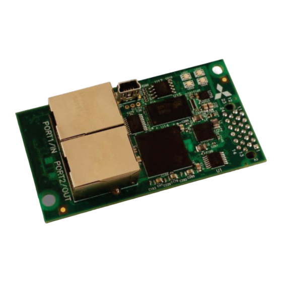
PRE-OPERATION INSTRUCTIONS 1.4.2 Component Overview LEDs (Refer to section 1.5) Mounting hole USB port Ethernet Port1 and Port2 Inverter connector (on back) Mounting hole... -
Page 36: Led Indicators
PRE-OPERATION INSTRUCTIONS LED Indicators The upper right-hand corner of the option board contains several bi-color LEDs (visible through the LED display cover after mounting) that provide a visual indication of the unit’s overall status. Ethernet Port 2 Ethernet Port 1 Module Status / LED3 Network Status / LED4 1.5.1 Port Status LED Description... -
Page 37: Standard Led Description
PRE-OPERATION INSTRUCTIONS 1.5.2 Standard LED Description Module Status (MS) Status Note Activity Device Off The inverter power is off Green Blink, Startup Startup blink sequence Red Blink Green On Device On Normal status Discovery Green Blink PROFINET discovery and identification (DCP) Identification Red Blink Error Code... -
Page 38: Ethercat Led Description
PRE-OPERATION INSTRUCTIONS 1.5.3 EtherCAT LED Description Run (LED3) LED Activity Slave State Note Device Off or The inverter power is off or the device is in state INIT INITIALISATION Green Blink, Startup blink sequence; the device is booting and has not Red Blink or INITIALISATION yet entered the INIT state... - Page 39 PRE-OPERATION INSTRUCTIONS Error (LED4) LED Activity Status Note The inverter power is off or the EtherCAT communication Device Off or No Error of the device is in working condition Green Blink, Startup Startup blink sequence Red Blink Application Controller A critical communication or application controller error Red On Failure has occurred...
-
Page 40: Installation
INSTALLATION INSTALLATION Pre-Installation Instructions Make sure that the inverter’s input power is off. CAUTION To avoid damage to the inverter or plug-in option card, never install or remove a plug- in option card while the inverter’s input power is on. - Page 41 Mitsubishi’s products and solutions undergo continuous development to make them more secure. Mitsubishi strongly recommends the application of product updates as soon as they are available. The use of product versions that are no longer supported, and the failure to apply the latest available...
-
Page 42: A700 & F700 Installation Procedure
INSTALLATION A700 & F700 Installation Procedure 2.2.1 Installation of the Communication Option LED Display Cover Mount the LED display cover on the inverter front cover. 1) Cut off the tabs on the backside of the inverter 2) Fit the LED display cover into the knockout front cover with a nipper, etc. -
Page 43: Installation Of The Communication Option On Control Board
INSTALLATION 2.2.2 Installation of the Communication Option on Control Board 1) Remove the inverter’s front cover. 2) Locate option connector 3 (lowermost connector) and screw the included M3x10mm hex standoff into the corresponding ground plate screw hole (rated torque 0.56Nm to 0.75Nm). 3) Securely attach the option card to the inverter’s option connector. - Page 44 INSTALLATION 5) Tighten both mounting screws to a torque setting of 0.33 N·m to 0.40 N·m. REMOVAL First remove the two M3x6mm mounting screws. Lastly, remove the option board by grasping it on its left and right side and pulling it straight away from the inverter. Note that the removal process may be easier by first removing the inverter’s control circuit terminal block.
-
Page 45: E700 Installation Procedure
INSTALLATION E700 Installation Procedure 1) Remove the inverter’s front cover. 2) Securely attach the option card to the inverter’s option connector. Ensure that the option card is fully seated on the option connector. 3) Secure the upper-left corner of the option card with the included M3x6mm pan head mounting screw. -
Page 46: Wiring
INSTALLATION Wiring When installing the option card into an FR-A720-00900-NA (FR-A740-00440-NA) or smaller inverter, remove the wiring access knockout on the front cover and route the network cable through the opening. When installing the option card into an FR-A720-01150-NA (FR-A740-00570-NA) or larger inverter, route the network cable through the space adjacent to the control circuit terminal block. -
Page 47: Inverter Settings
INVERTER SETTINGS INVERTER SETTINGS The inverter parameters listed in Table 16 are critical for overall operation of the end-to-end communication system. Some of these parameters must be set to specific values, and some may have multiple allowable settings depending on the desired operation of the overall application. Although there may be many other inverter parameters that will require configuration for your specific application, it is important to understand the manner in which the following parameters will impact successful communications with, and control of the inverter. -
Page 48: Network Setting
INVERTER SETTINGS Network Setting The network settings can optionally be set using the inverter parameters described in the Table 17. An invalid parameter value will void the inverter network parameters and fallback to the network settings created by the Configuration Studio or the default network settings (IP address = 192.168.16.100, Subnet mask = 255.255.255.0, and Default gateway = 192.168.16.3). - Page 49 INVERTER SETTINGS IP Address The IP address is created from the octet values specified in Pr. 232, Pr. 233, Pr. 234, and Pr. 235. The value after the decimal point for each parameter value must be 0. Subnet Mask The subnet mask is created from the octet values specified in Pr. 236, Pr. 237, Pr. 238, and Pr. 239. The value after the decimal point for each parameter value must be 0.
-
Page 50: Operation Mode Setting
INVERTER SETTINGS Operation Mode Setting Three operation modes are available when a communication option card is installed into an inverter. 1. PU operation [PU] ....The inverter is controlled by the operating panel (FR-DU07). 2. External operation [EXT] ... The inverter is controlled by the ON/OFF switching of external signals connected to the control circuit terminals (factory default.) 3. -
Page 51: Operation Mode Switching & Comm. Startup Mode (Pr. 79, Pr. 340)
INVERTER SETTINGS 3.2.2 Operation Mode Switching & Comm. Startup Mode (Pr. 79, Pr. 340) (1) Operation mode switching conditions Prior to switching the operation mode, confirm that: 1) The inverter is stopped 2) Both the STF and STR signals are off 3) The Pr. - Page 52 INVERTER SETTINGS Pr. 340 Pr. 79 Operation Mode at Power-On or Power Operation Mode Switchover Setting Setting Recovery Switching among external, PU, and NET operation modes is External operation mode (default) enabled PU operation mode PU operation mode fixed Switching between external and NET operation modes is External operation mode enabled, switching to PU operation mode is disallowed 3, 4...
- Page 53 INVERTER SETTINGS Pr. 340 settings "2” and “12" are mainly used for communication operation using the inverter’s RS-485 port. When a value other than "9999" (automatic restart after momentary power failure) is set in Pr. 57 Restart coasting time, the inverter will resume the same operation state which it was in prior to a momentary power failure is such a failure occurs.
- Page 54 INVERTER SETTINGS (3) Operation mode switching method For a switching method via external terminal input signals, refer to the inverter’s user’s manual (applied). • When starting the inverter in NET mode upon powering-up or after an inverter reset, set a value other than 0 in Pr.
-
Page 55: Operation & Speed Command Source (Pr. 338, Pr. 339, Pr. 550)
INVERTER SETTINGS Operation & Speed Command Source (Pr. 338, Pr. 339, Pr. 550) (1) Select control source for NET mode (Pr. 550) The control location for NET mode can be selected to be from either the inverter’s RS-485 port or a plug-on communication option card. - Page 56 INVERTER SETTINGS (2) Selection of control source for NET mode (Pr. 338, Pr. 339) Control sources can be subdivided into two separate realms: 1) operation commands such as start/stop signals, etc. and 2) the speed command source that determines the inverter’s frequency command. The various combinations of these realms that can be configured are summarized in the following table.
- Page 57 INVERTER SETTINGS...
- Page 58 INVERTER SETTINGS *1: Available only when used with the FR-A7AP. [Table explanation] External ....Only external terminal input control is valid. NET ..... Only network control is valid. Combined .... Either external terminal input control or network control is valid. - ......
-
Page 59: Communication Eeprom Write Selection (Pr. 342)
INVERTER SETTINGS Communication EEPROM Write Selection (Pr. 342) When parameters are written via communications, by default both volatile RAM and nonvolatile EEPROM contents are modified. Due to the limited write cycle lifetime of EEPROM memory, however, it may be desirable to modify only the contents of RAM when frequent parameter writes via communications are necessary. -
Page 60: Register Numbering And Behavior
(1 to 7) and monitor registers (100 and 101) are included in this manual for user convenience, but more information can be found in the inverter user manual “Mitsubishi inverter protocol” section. Monitor registers 201 to 254 are documented in the inverter user manual “Monitor description list”. For information regarding the remaining inverter parameters, refer to the inverter user manual “Parameter... - Page 61 REGISTER NUMBERING AND BEHAVIOR Table 18: Register Parameter List Register Description Command register (refer to section 4.3) Frequency command (RAM) (refer to section 4.4) Frequency command (EEPROM) (refer to section 4.4) Operation mode setting (refer to section 4.5) Inverter reset (refer to section 4.6) Alarm history clear (refer to section 4.7) All parameter clear (refer to section 4.8) Inverter status (refer to section 4.9)
- Page 62 REGISTER NUMBERING AND BEHAVIOR Register Description Input power Output power Input terminal status Output terminal status Load meter Motor excitation current Position pulse Cumulative energization time Orientation status Actual operation time Motor load factor Cumulative power Torque command Torque current command Motor output Feedback pulse Power saving effect...
-
Page 63: Scanned Registers
REGISTER NUMBERING AND BEHAVIOR Register Description Alarm history 2 (refer to Table 23) Alarm history 3 (refer to Table 23) Alarm history 4 (refer to Table 23) Alarm history 5 (refer to Table 23) Alarm history 6 (refer to Table 23) Alarm history 7 (refer to Table 23) Alarm history 8 –... - Page 64 REGISTER NUMBERING AND BEHAVIOR corresponding error. However, the register can be read over the network at a later time to confirm whether or not that the written value “took hold” in the inverter. Even if an inverter parameter corresponding to a given scanned register does not exist, the interface card still maintains a placeholder location in its internal mirroring memory for that register.
-
Page 65: Inverter Command Register
REGISTER NUMBERING AND BEHAVIOR Inverter Command Register The command word is register 1 and the bit-mapping is described in Table 19. Refer to the specific inverter user manual to confirm the bit-mapping and signal settings. Table 19: Inverter Command Register The signal within parentheses is the initial setting. -
Page 66: Frequency Command Register
REGISTER NUMBERING AND BEHAVIOR 11 are invalid in the initial status. When using bit 8 to bit 11, change the signals with Pr. 185, Pr. 186, Pr. 188, Pr. 189 (input terminal function selection). Frequency Command Register The frequency command (RAM) is register 2 and the frequency command (EEPROM) is register 3. The frequency is in 0.01Hz increments. -
Page 67: Operation Mode Register
REGISTER NUMBERING AND BEHAVIOR Operation Mode Register The operation mode is register 4 and the modes are described in Table 20. Because this write-only inverter register cannot be read by the interface card, there are no guarantees that the interface card’s local value matches the current mode command value in the inverter. -
Page 68: Alarm History Clear Register
REGISTER NUMBERING AND BEHAVIOR Alarm History Clear Register The alarm history clear is register 6. A value of 0x9696 will clear the alarm history. All Parameter Clear Register The all parameter clear is register 7. Refer to Table 21 for the appropriate value. Table 21: All Parameter Clear Register Refer to communication related parameters. -
Page 69: Inverter Status Register
REGISTER NUMBERING AND BEHAVIOR Inverter Status Register The inverter status is register 100 and the bit-mapping is described in Table 22. Refer to the specific inverter user manual to confirm the bit-mapping and signal settings. Table 22: Inverter Status Register The signal within parentheses is the initial setting. -
Page 70: Operation Mode Status Register
REGISTER NUMBERING AND BEHAVIOR 4.10 Operation Mode Status Register The operation mode status is register 101 and the bit-mapping is described in Table 20. 4.11 Alarm History Codes The alarm history codes are listed in Table 23. The alarm codes are described in the inverter user manual “List of alarm display”... -
Page 71: Mitsubishi Configuration Studio
MITSUBISHI CONFIGURATION STUDIO MITSUBISHI CONFIGURATION STUDIO Overview Figure 1: Mitsubishi Configuration Studio... - Page 72 MITSUBISHI CONFIGURATION STUDIO The card is discovered, configured and updated by the Mitsubishi Configuration Studio PC application. The studio must be installed prior to connecting a card to ensure that the appropriate USB drivers are installed. The studio will typically require a USB connection for reading/writing a configuration and updating the firmware.
- Page 73 MITSUBISHI CONFIGURATION STUDIO Going Online with a Device All connected devices are automatically added to the Discovered Devices panel. This panel is shown by selecting the Online Devices list heading in the Project panel. To go online with a device: Double-click on it in the Discovered Devices panel.
- Page 74 MITSUBISHI CONFIGURATION STUDIO Selecting it and clicking the Upload Configuration button in the toolbar. • The device’s configuration will then be added to the list of Device Configurations. Once the configuration is uploaded into the project, it may be modified.
- Page 75 MITSUBISHI CONFIGURATION STUDIO Right-click on the device in the Project panel and choose Go Offline from the context-sensitive • menu. Select Go Offline with Device from the Edit menu when the device is selected. • • Click on the Go Offline button in the toolbar when the device is selected.
-
Page 76: General Object Editing Activities
MITSUBISHI CONFIGURATION STUDIO General Configuration Process To configure a device, add the desired protocol(s) and configure any objects associated with the respective protocol(s). Any changes will take effect once the configuration is downloaded to a device. Note that numeric values can be entered not only in decimal but also in hexadecimal by including “0x”... - Page 77 MITSUBISHI CONFIGURATION STUDIO The object’s configurable fields can then be populated with valid values (where applicable). Viewing an Object In the Project panel, select a parent object to display a summary of all its child objects. For example, selecting a protocol driver will display the driver’s configuration in the Summary panel and list of current objects in the Object List panel.
- Page 78 MITSUBISHI CONFIGURATION STUDIO Copying and Pasting an Object To copy an object, first click on an item in the Project panel. An object can then be copied by: Right-clicking on it and choosing Copy from the context-sensitive menu. • Pressing the <CTRL+C> keys on the keyboard.
-
Page 79: Ethernet Settings
MITSUBISHI CONFIGURATION STUDIO After pasting an object, the object’s configurable fields can then be modified with valid values (where applicable). Note that the studio allows you to copy and paste items between different locations, including different devices. This is useful for copying partial configurations from one device to another. -
Page 80: Network Configuration
MITSUBISHI CONFIGURATION STUDIO Password The password is case-sensitive and can contain letters (“a...z” and “A...Z”) and numbers (“0…9”). 5.3.2 Network Configuration The card supports a static IP address. The IP Address, Subnet Mask and Default Gateway fields must be configured. Please consult with your network administrator for the proper settings of these fields. -
Page 81: Timeout Time
MITSUBISHI CONFIGURATION STUDIO 5.4.2 Timeout Time The timeout time is the maximum number of milliseconds for a break in network communications before a timeout will be triggered. This timeout setting is configured at the protocol level as part of a driver’s configuration, and used by the protocol drivers themselves to determine abnormal loss-of- communications conditions. - Page 82 MITSUBISHI CONFIGURATION STUDIO Register Enter the register number (refer to section 4) corresponding to the inverter parameter. Data Type This is the size of valid values and is fixed to “16-Bit Unsigned” allows for a range of timeout values between 0 and 65535.
-
Page 83: Discovery Over Ethernet
MITSUBISHI CONFIGURATION STUDIO Discovery over Ethernet Depending on the currently-enabled driver, the Configuration Studio will automatically discover the device on the current Ethernet network, regardless of whether or not the card’s network settings are compatible with the subnet upon which they reside. All connected devices are automatically added to the Discovered Devices panel. -
Page 84: Manage Device Parameters
MITSUBISHI CONFIGURATION STUDIO The network settings of a discovered card can be configured remotely by: Right-clicking on the device in the Project panel and • choosing Configure Network Settings… from the context- sensitive menu. Selecting the device in the Project panel and navigating to •... - Page 85 MITSUBISHI CONFIGURATION STUDIO A parameter is accessible and actively scanned (read from and written to the inverter) only if its corresponding checkbox is enabled. Likewise, a parameter is inaccessible if its checkbox is disabled. Parameters that are accessed more frequently or require a faster update rate should be set to high priority.
-
Page 86: Backup And Restore Parameters
MITSUBISHI CONFIGURATION STUDIO Backup and Restore Parameters The parameter values can be backed up from the inverter and restored to the inverter (refer to Figure 5 and Figure 6). This allows for easy inverter cloning. The backup parameter values are stored as a CSV file. - Page 87 MITSUBISHI CONFIGURATION STUDIO Figure 5: Backup Parameters...
- Page 88 MITSUBISHI CONFIGURATION STUDIO Figure 6: Restore Parameters...
-
Page 89: Restore Factory Settings
MITSUBISHI CONFIGURATION STUDIO Restore Factory Settings The interface card (connected via USB) can be restored to the factory settings. Note that the filesystem will be reformatted, which will destroy all custom modifications and configurations. Please backup the configuration before executing this feature. The factory settings can be restored by: Right-clicking on the device in the Project panel and choosing Restore Factory Settings. -
Page 90: Help
MITSUBISHI CONFIGURATION STUDIO Current Status Table 24: Diagnostic Codes Indicates the status of the most-recently received Diagnostic Code packet. This field is updated each time the “RX Description (Hex) Counter” or “RX Error Counter” increments. Refer to Table 24 for a list of supported codes. -
Page 91: Embedded Web Server
EMBEDDED WEB SERVER EMBEDDED WEB SERVER Overview The interface contains an embedded (HTTP) web server, which allows users to access the inverter’s internal data in a graphical manner with web browsers such as Microsoft Internet Explorer or Mozilla Firefox. In this way, the inverter can be monitored and controlled from across the room or from across the globe. - Page 92 EMBEDDED WEB SERVER Figure 7: Embedded Web Server...
-
Page 93: Monitor Tab
EMBEDDED WEB SERVER Monitor Tab 6.2.1 Information Window Figure 8: Monitor Tab Information Window Figure 8 shows the Information Window, which displays messages regarding the status of the interface card or web browser session. There is also an “ACTIVITY” indicator which blinks periodically to show the status of data communication between the web browser and the interface card. -
Page 94: Parameter List
EMBEDDED WEB SERVER group, and then holding down the SHIFT key while selecting the last group in the range. When a parameter group is selected, the parameters contained in that parameter group are displayed in the Parameter List (refer to section 6.2.3). 6.2.3 Parameter List The parameter list is shown in Figure 10. - Page 95 EMBEDDED WEB SERVER Figure 10: Parameter List Some items to keep in mind when interacting with the Parameter List are: • When entering new parameter values, be sure that the number being entered is appropriate for the currently-selected radix (refer to section 6.2.5). The column widths can be changed by dragging the vertical bars that separate the header row’s •...
-
Page 96: Parameter List Filter
EMBEDDED WEB SERVER • If you begin changing a parameter value and then decide to abandon the change, pressing the ESC key on your keyboard will abandon the change and redisplay the current parameter value. When editing a parameter value, clicking someplace off the entry cell is equivalent to hitting the •... - Page 97 EMBEDDED WEB SERVER Similarly, when “HEX” is selected, the “value” column heading will be “Value (Hexadecimal)”, current parameter values will be displayed in hexadecimal, and values to be written to parameters must be entered in hexadecimal format.
-
Page 98: Dashboard Tab
EMBEDDED WEB SERVER Dashboard Tab Figure 13: Dashboard Tab... -
Page 99: Information Window
EMBEDDED WEB SERVER The Dashboard Tab provides access to a variety of gauges, meters and graphs that can be configured to provide an at-a-glance graphical overview of application variables in real-time. A total of 10 gauge windows are available (four at a time), and each gauge window can be configured to display any register’s value via one of six different gauge types. -
Page 100: Gauge Window Configuration
EMBEDDED WEB SERVER 6.3.3 Gauge Window Configuration Each of the gauge windows can be independently configured to display a user-defined register with a variety of flexible configuration options. While the behavior and presentation may vary slightly depending on the specific gauge chosen, all of the gauges share the following common elements (refer to Figure 16 for an example): Gauge Selector: A drop-down selection box in the upper left-hand corner of the gauge window, which allows the user to select the type of gauge that will be displayed. - Page 101 EMBEDDED WEB SERVER Max Value: The gauge’s maximum indicated value. Similar to the Min Value attribute, negative values can be used if desired. Indicated value characteristics can even be inverted by setting the Max Value attribute to a value less than the Min Value attribute. Update Button: Clicking the update button will apply the current configuration attribute settings to the gauge.
- Page 102 EMBEDDED WEB SERVER BarGraph: Refer to Figure 17. This type of meter implements a linear bar graph display format. Hovering the mouse pointer over the red portion of the graph pops up a tooltip which displays the current indicated value and units. Figure 17: BarGraph Meter: Refer to Figure 18.
- Page 103 EMBEDDED WEB SERVER Pos/Neg Meter: Refer to Figure 19. Similar to the “meter” gauge, this type of meter also implements a common panel meter-type display format, but in this instance the indicated value can be positive or negative (two’s complement interpretation).
- Page 104 EMBEDDED WEB SERVER Line Graph: Refer to Figure 21. This type of graph implements a continuously-scrolling historical data logging line graph. Up to 80 seconds worth of historical data is available. Hovering the mouse pointer anywhere on the graph displays a vertical reference line at the corresponding time, and pops up a tooltip which displays the current indicated value at that time.
-
Page 105: Submitting Changes
EMBEDDED WEB SERVER 6.3.4 Submitting Changes Whenever any of the gauge window configuration items in the Dashboard Tab have been changed, the “submit” button located on the right-hand portion of the web page must be selected in order to write these settings to the interface card’s filesystem. -
Page 106: Customizing The Embedded Web Server
EMBEDDED WEB SERVER Customizing the Embedded Web Server 6.4.1 Customization Overview It is possible for end-users to customize the embedded web server in order to create their own application-specific or corporate “look and feel”. Knowledge of authoring dynamic web content is required. -
Page 107: Xtpro Overview
EMBEDDED WEB SERVER 6.4.2 XTPro Overview XTPro is an acronym for XML TCP/IP Protocol. The XTPro specification is an application-layer (positioned at level 7 of the OSI model) messaging protocol that provides XML-based client/server communication via TCP port 843. Typically, XTPro is used for the implementation of graphical user interfaces (GUIs), such as advanced web servers or HMIs that have the ability to request information via XML sockets, and then manipulate and/or display the information in a rich application-specific manner. - Page 108 EMBEDDED WEB SERVER trogrammer authors active web page content (via Adobe Content is loaded onto Flash, etc.) server device’s file system for web server Active web content http://192.168.16.111 is delivered to client Network or User accesses HTTt (port 80) Internet server’s web page via web Server...
-
Page 109: Xtpro Hmi-Based Implementation
EMBEDDED WEB SERVER 6.4.4 XTPro HMI-Based Implementation A representative implementation based upon a stand-alone HMI client is detailed in Figure 25. In this scenario, the client application is developed by using tools provided by the HMI manufacturer, and is hosted independently of the actual server device. trogrammer authors HMI (client) content Content is loaded... -
Page 110: Xtpro Supported Commands
EMBEDDED WEB SERVER 6.4.5 XTPro Supported Commands For a summary of the supported XTPro commands, refer to Table 25. Note that two simultaneous XTPro connections are available. Table 25: Supported XTPro Commands Command Supported Notes noop Supports XTPro specification version 1 read_data “reference”... -
Page 111: Filesystem
FILESYSTEM FILESYSTEM Overview The interface card’s on-board filesystem is used by the application firmware. Currently, the application firmware’s main use of the filesystem is to store XML-encoded configuration files and the embedded web server. The studio must be used to manage the configuration via USB or FTP. Do not manually access the configuration files unless instructed by technical support. -
Page 112: Usb With Windows Explorer
FILESYSTEM maintenance and configuration. USB and FTP should be disconnected while the card is running normally in a production environment. USB with Windows Explorer To use Microsoft Windows Explorer, first open either “Windows Explorer” or “My Computer”. Refer to Figure 26. Note that the indicated procedure, prompts and capabilities outlined here can vary depending on such factors as the installed operating system and service packs. -
Page 113: Ftp With Windows Explorer
FILESYSTEM Windows Explorer will then display the filesystem’s contents (refer to Figure 28.) You can now perform normal file manipulation actions on the available files and folders (cut, copy, paste, open, rename, drag- and-drop transfers etc.) in the same manner as though you were manipulating any traditional file and folder stored on your computer’s hard drive. - Page 114 FILESYSTEM In the “Address” field, type in “ftp://admin:admin@” and then the IP address of the target interface card (if the user name and password have been changed from its default, then replace the first “admin” with the new user name and the second “admin” with the password.) Refer to Figure 29. Figure 29: FTP via Windows Explorer Note that the behavior of Windows Explorer FTP will vary from PC to PC.
-
Page 115: Loading New Web Server Content
FILESYSTEM Loading New Web Server Content The interface card’s web server resides in the file system and can be updated in the field (refer to section 6.4). This section will discuss how to update the default web server. The update procedure similarly applies to a custom web server. -
Page 116: Firmware
FIRMWARE FIRMWARE Overview The interface card’s embedded firmware can be updated in the field. Firmware updates may be released for a variety of reasons, such as custom firmware implementations, firmware improvements and added functionality as a result of user requests. Additionally, it may be necessary to load different firmware onto the unit in order to support various protocols. - Page 117 FIRMWARE 4. Ensure that the device is in a safe state prior to initiating the firmware update. The card may be temporarily inaccessible during the firmware update process. 5. Locally via USB: Connect a USB cable between the card and the PC and open the studio. If the studio contains newer firmware, it will automatically prompt you to update the firmware.
-
Page 118: Protocol-Specific Information
PROTOCOL-SPECIFIC INFORMATION PROTOCOL-SPECIFIC INFORMATION This section will discuss topics that are specific to each of the supported protocols. Modbus/TCP Server 9.1.1 Overview The interface card supports Table 26: Supported Modbus/TCP Functions Schneider Electric’s Modbus/TCP protocol, release 1.0. The interface is Function Modbus/TCP Function... -
Page 119: Holding & Input Registers
PROTOCOL-SPECIFIC INFORMATION Inverter registers can be addressed as holding registers (4X references) and input registers (3X • references). Specific bits within inverter registers can be accessed as either coils (0X references) or discrete • inputs (1X references). Write data checking is not available (refer to section 4.2.) For example, if a write is performed to a •... -
Page 120: Coil & Discrete Input Mappings
PROTOCOL-SPECIFIC INFORMATION 9.1.3 Coil & Discrete Input Mappings The Modbus/TCP driver provides read/write support for coils (0X references) and read-only support for discrete inputs (1X references). These will collectively be referred to from here on out as simply “discretes”. Accessing discretes does not reference any new physical data: discretes are simply indexes into various bits of existing registers. -
Page 121: Connection Timeout Options
PROTOCOL-SPECIFIC INFORMATION Where “discrete” ∈[1…65535], “bit” ∈[0…15], and “%” is the modulus operator, which means that any fractional result (or “remainder”) is to be retained, with the integer value being discarded (i.e. it is the opposite of the “floor” function). For clarity, let’s use Equation 1 and Equation 2 in a calculation example. - Page 122 PROTOCOL-SPECIFIC INFORMATION If the driver experiences no receive activity for more than the Timeout time setting, then the driver • assumes that the client or network has experienced some sort of unexpected problem, and will perform the Timeout Action. Enable Connection Timer This timer provides the ability for the driver to monitor timeout occurrences and errors within the scope of each client connection.
-
Page 123: Node Settings
PROTOCOL-SPECIFIC INFORMATION “None”........No effect. The inverter will continue to operate with the last available settings. “Apply Fail-safe Values” ..Apply the fail-safe values as described in section 5.4.1. 9.1.5 Node Settings There are no node settings. A node is simply a container for objects. 9.1.6 Holding/Input Register Remap Settings In the studio’s Project panel, add A7NETH-2P…Ethernet…Modbus/TCP Server…Holding/Input Register Remap. - Page 124 PROTOCOL-SPECIFIC INFORMATION 2. Implement one single Modbus read transaction, starting at register 201 for a quantity of 54 registers. Then, pick out the registers of interest and ignore the rest of the response data. While both of these methods will certainly work, neither one of them is optimized for the task at hand, which is to access three specific register values.
-
Page 125: Ethernet/Ip Server
PROTOCOL-SPECIFIC INFORMATION EtherNet/IP Server 9.2.1 Overview EtherNet/IP is a network adaptation of ODVA’s Common Industrial Protocol (CIP). The card supports the EtherNet/IP server protocol, including the CSP server variant. The interface card supports both implicit (class 1 I/O) and explicit (UCMM and class 3) messaging. Class 1 connections support two different types of I/O messaging. - Page 126 PROTOCOL-SPECIFIC INFORMATION • This product has been self-tested and found to comply with ODVA EtherNet/IP Conformance Test Software Version CT-13. The interface card’s product type code is 2 (AC Drive). • The EDS file can be obtained from the included CD-ROM or downloaded from the product web •...
-
Page 127: Server Settings
PROTOCOL-SPECIFIC INFORMATION 9.2.2 Server Settings In the studio, navigate to A7NETH-2P…Ethernet…EtherNet/IP Server. Device Name The device name is used for identification of a device on the EtherNet/IP network. This string is accessible as the “product name” attribute of the identity object. Enter a string between 1 and 32 characters in length. - Page 128 PROTOCOL-SPECIFIC INFORMATION Run/Idle Flag Behavior EtherNet/IP clients (such as PLCs) have the option of adding a 32-bit “run/idle” header to all class 1 (I/O) data packets sent to devices. Bit 0 of this header is called the “run/idle flag” by the EtherNet/IP specification, and is intended to signify when the client is in a “running”...
-
Page 129: Generic Class 1 I/O Produced And Consumed Data Settings
PROTOCOL-SPECIFIC INFORMATION 9.2.4 Generic Class 1 I/O Produced and Consumed Data Settings In the studio’s Project panel, add A7NETH-2P…Ethernet…EtherNet/IP Server…Produced I/O Data…Produced Data Word and/or Consumed I/O Data…Consumed Data Word. The Produced Data Word and Consumed Data Word objects are only applicable when connecting to assembly instances 100 and 150 (generic I/O), which is typically the case. - Page 130 PROTOCOL-SPECIFIC INFORMATION Consumed Data Word Offset The consumed data received from the client at this word offset will contain the value to be written to the associated inverter register. It is recommend to start at word offset 0. Register The inverter register (refer to section 4) associated with the word offset. For the Produced Data Word object, enter a “status”...
-
Page 131: Generic Class 1 (I/O) Connection Access
PROTOCOL-SPECIFIC INFORMATION The default I/O configuration is described in Table 28. Always use the studio to confirm the configuration before commissioning the device. Table 28: EtherNet/IP Default User-Configurable I/O Data Format Consumed Data Produced Data (PLC to Inverter) (Inverter to PLC) Word Offset Register Word Offset... - Page 132 PROTOCOL-SPECIFIC INFORMATION Table 30 and Table 33) to 4 input bytes and 4 output bytes. It is highly recommended to complete the reading of this section to understand the data mapping and the implications of using the AC/DC drive profile. Note that when using the AC/DC drive profile class 1 I/O, the produced word and consumed word configuration do not apply (refer to section 9.2.4).
- Page 133 PROTOCOL-SPECIFIC INFORMATION Table 30: Output Instances 20 and 21 Detail Instance Byte Bit 7 Bit 6 Bit 5 Bit 4 Bit 3 Bit 2 Bit 1 Bit 0 Fault Reset Speed Reference (Low Byte) Speed Reference (High Byte) Fault NetRef NetCtrl Reset Speed Reference (Low Byte)
- Page 134 PROTOCOL-SPECIFIC INFORMATION NetCtrl: Run/stop control source selection (0=local control, 1=network control). Maps to inverter register 4 (operation mode). NetRef: Speed reference source selection (0=local control, 1=network control). Maps to inverter register 4 (operation mode). NetCtrl and NetRef explanation: Although the intent of Table 31: NetCtrl/NetRef Behavior these bits is to be able to independently separate the “Operation Mode”...
- Page 135 PROTOCOL-SPECIFIC INFORMATION The RPM-to-Hz conversion equation is [RPM x number of motor poles / 120]. Table 32 indicates the scenarios under which the conversion equation is and is not applied, and the value used for the “number of motor poles” component in the numerator of the conversion equation. For more information on the manners in which Pr.
- Page 136 PROTOCOL-SPECIFIC INFORMATION Table 33: Input Instances 70 and 71 Detail Instance Byte Bit 7 Bit 6 Bit 5 Bit 4 Bit 3 Bit 2 Bit 1 Bit 0 Running1 Faulted Speed Actual (Low Byte) Speed Actual (High Byte) Ctrl Running2 Running1 From From...
- Page 137 PROTOCOL-SPECIFIC INFORMATION the setting of inverter parameter Pr. 190 (RUN terminal function selection) is changed from its factory- default value, the indicated status of the Running1 bit will no longer be accurate. Running2 (REV): Running reverse status signal (0=not running reverse, 1=running reverse). Maps to inverter register 100 (status word), bits 0 and 2.
-
Page 138: Explicit Messaging Via Get/Set Attribute Single Services
PROTOCOL-SPECIFIC INFORMATION Drive State: Indicates the current state of the Control Supervisor Object state machine. Refer to the ODVA EtherNet/IP specification (object library) for detailed information on the Control Supervisor Object state machine. Speed Actual: Inverter operating speed in RPM. Maps to inverter register 201 (output frequency). The output frequency value read from the inverter depends on the settings of parameters Pr. -
Page 139: Explicit Messaging Via Data Table Read/Write Services
PROTOCOL-SPECIFIC INFORMATION class code is 0xA2. The instance number is the targeted register number (refer to section 4.1). The attribute identifier is 1, which is the 16-bit value of the register being accessed. For example, a get attribute single request with a class code of 0xA2, instance number of 201, and attribute identifier of 1 will return the 16-bit value of the output frequency. - Page 140 PROTOCOL-SPECIFIC INFORMATION Where [reg] is just the 3-character sequence “reg”. [register number] is a 1- to 4-character field (“1”, “2”…”507”, “508”, “1000”, “1001”… etc.) corresponding to the inverter register number. Examples “Output voltage” (register #203) ..........reg_203 “Frequency command” (register #2) ........reg_2 “Inverter status”...
-
Page 141: Controllogix Examples: Setup
PROTOCOL-SPECIFIC INFORMATION 9.2.10 ControlLogix Examples: Setup This section will demonstrate how to initially setup a ControlLogix PLC (such as a 1756-L61) coupled with a 1756-ENBT communication interface (adjust this procedure according to your specific equipment). Later sections will provide specific read/write examples using this configuration with I/O or explicit messaging. -
Page 142: Controllogix Example: Eds Add-On Profile (Aop)
PROTOCOL-SPECIFIC INFORMATION 7) Assign the Ethernet module a name (we will use “EIP”) and an IP address, deselect “Open Module Properties”, and click OK. 8) Assign the Ethernet module a name (we will use “EIP”) and an IP address, deselect “Open Module Properties”, and click OK. - Page 143 PROTOCOL-SPECIFIC INFORMATION Otherwise, refer to the I/O examples in section 9.2.12. This section must be completed prior to attempting any of the following AOP example(s). EtherNet/IP I/O messaging allows the inverter’s parameter to be directly mapped into tags in the ControlLogix PLC.
- Page 144 PROTOCOL-SPECIFIC INFORMATION 3) Select “Register an EDS file(s)” and click “Next”. 4) The “Registration” dialog will appear. Refer to Figure 33. Click “Browse”, select the interface card’s EDS file, and click “Next”. Figure 33: EDS Registration 5) Ensure that there are no errors in the test results. Click “Next”. 6) A graphic image of the interface card is displayed.
- Page 145 PROTOCOL-SPECIFIC INFORMATION 7) The task summary will list the interface card as the device to register. Click “Next”. 8) “You have successfully completed the EDS Wizard”. Click “Finish”. 9) The interface card is now available as a module. 10) Right click on the 1756-ENBT/A node under the “I/O Configuration” in the controller organizer view and choose “New Module…”...
- Page 146 PROTOCOL-SPECIFIC INFORMATION 12) The “New Module” properties dialog box will open as shown in Figure 35. Figure 35: AOP Interface Card Module Properties...
- Page 147 PROTOCOL-SPECIFIC INFORMATION 13) Click on the “Connection” tab. Refer to Figure 36. Figure 36: AOP New Module Properties Connection Tab...
-
Page 148: Controllogix Example: Eds Add-On Profile (Aop) Generic I/O Messaging
PROTOCOL-SPECIFIC INFORMATION Confirm the setting of the “Requested Packet Interval (RPI)”. The RPI defines the amount of time (in milliseconds) between data exchanges across an I/O connection. The smallest RPI supported by the interface card is 1ms. Click “OK” when done. 14) You should now see the interface card in the 1756-ENBT/A branch under the I/O Configuration in the controller organizer view. - Page 149 PROTOCOL-SPECIFIC INFORMATION 3) Configure the Generic I/O connection. Refer to Figure 38. Figure 38: AOP Generic I/O Module Definition In the “Connection” portion of the dialog box, enter the following information: Name: In this example, select Generic I/O. Size: Because all inverter data is stored as 16-bit function codes, change the data type to “INT array”.
- Page 150 PROTOCOL-SPECIFIC INFORMATION Input: The Input is the collection of monitor data that is produced by the interface card and is received as an input to the PLC. Its structure is defined by the Produced Data Configuration as described in section 9.2.4. The Input Size must be set to the number of 16-bit function codes that we wish to receive from the interface card.
-
Page 151: Controllogix Example: Eds Add-On Profile (Aop) Ac/Dc Drive Profile
PROTOCOL-SPECIFIC INFORMATION 9.2.11.2 ControlLogix Example: EDS Add-On Profile (AOP) AC/DC Drive Profile This section will demonstrate how to configure the EtherNet/IP AC/DC drive profile I/O connection. 1) Complete all steps in section 9.2.11. 2) Locate the interface card in the 1756-ENBT/A branch under the “I/O Configuration” in the controller organizer view. - Page 152 PROTOCOL-SPECIFIC INFORMATION Figure 39: AOP AC/DC Drive Profile Module Definition In the “Connection” portion of the dialog box, enter the following information: Name: In this example, select AC/DC Drive Profile 21 71. Size: Because all inverter data is stored as 16-bit function codes, change the data type to “INT array”.
- Page 153 PROTOCOL-SPECIFIC INFORMATION When done, click “OK”. 4) Switch to online mode and download the project to the PLC. Verify that the newly-added inverter is available and operating correctly by observing any indications shown on the inverter’s icon. When the inverter’s icon is selected, its status and any available error messages will be displayed in the area below the project tree.
-
Page 154: Controllogix Example: I/O Messaging
PROTOCOL-SPECIFIC INFORMATION 9.2.12 ControlLogix Example: I/O Messaging This section will demonstrate how to setup and use an EtherNet/IP I/O connection via vendor-specific assembly instances 100 & 150 or 20 & 70 or 20 & 71. EtherNet/IP I/O messaging allows the inverter’s registers to be directly mapped into tags in the ControlLogix PLC. - Page 155 PROTOCOL-SPECIFIC INFORMATION change the “Comm Format” selection to “Data-INT”. Enter the IP address of the targeted interface card. In the “Connection Parameters” portion of the dialog box, enter the following information: Input: The Input Assembly is the collection of monitor data that is produced by the interface card and is received as an input to the PLC.
- Page 156 PROTOCOL-SPECIFIC INFORMATION 100 when connecting to the generic I/O assembly instances (or 20/21 when using the ODVA AC/DC drive profile), and the size must be set to the number of 16-bit registers that we wish to send to the interface card. For the purposes of this example, we are assuming that the default consumed data word configuration, with two relevant registers (1 and 2).
- Page 157 PROTOCOL-SPECIFIC INFORMATION interface card is 1ms. Click OK when done. 21) After adding the I/O Module to the configuration, the full I/O Configuration tree should appear similar to Figure 43. 22) Switch to online mode and download the project to the PLC. Verify that the newly-added inverter is available and operating correctly by observing any indications shown on the inverter’s icon.
- Page 158 PROTOCOL-SPECIFIC INFORMATION inverter’s command register. A value of 0x0002, therefore, means that the run forward bit has been turned ON. Figure 45: Controller Tags for I/O Access Similarly, we can see that the second 16-bit word of output data (Interface_Card:O.Data[1]) has been set to a decimal value of 6000.
-
Page 159: Controllogix Example: Generic Default I/O Add-On Instruction
PROTOCOL-SPECIFIC INFORMATION 9.2.12.1 ControlLogix Example: Generic Default I/O Add-On Instruction The generic default I/O add-on instruction is a simple interface to command and monitor the inverter. It is based on the vendor-specific assembly instances 100 & 150 and the default produce and consume data configuration (refer to section 9.2.4). - Page 160 PROTOCOL-SPECIFIC INFORMATION Figure 47: Create Generic Default AOI Tags 5) Double click “MainRoutine” under Tasks…MainTask…MainProgram in the controller organizer view. 6) Right click on the first ladder logic rung in the MainRoutine window and select “Add Ladder Element...” 7) The “Add Ladder Element” window appears. 8) Select the generic default I/O add-on instruction in the Add-On folder.
- Page 161 PROTOCOL-SPECIFIC INFORMATION 12) Save, download and run the program. Figure 48: Add Generic Default Add-On Instruction Figure 49: Configure Generic Default AOI...
-
Page 162: Controllogix Example: Ac/Dc Drive Profile Add-On Instruction
PROTOCOL-SPECIFIC INFORMATION 9.2.12.2 ControlLogix Example: AC/DC Drive Profile Add-On Instruction The AC/DC drive profile add-on instruction is a simple interface to command and monitor the inverter. It is based on the assembly instances 21 & 71. 1) Complete all the steps in section 9.2.12. Please note that the Assembly Input Instance must be changed to 71 and the Assembly Output Instance must be changed to 21. - Page 163 PROTOCOL-SPECIFIC INFORMATION 2) Right click on “Add-On Instructions” in the controller organizer view and select “Import Add-On Instruction”. Browse and import the AC/DC drive profile add-on instruction. Refer to Figure 51. 3) Double click “Controller Tags” in the controller organizer view and select the “Edit Tags”...
- Page 164 PROTOCOL-SPECIFIC INFORMATION 5) Double click “MainRoutine” under Tasks …MainTask …MainProgram in the controller organizer view. 6) Right click on the first ladder logic rung in the MainRoutine window and select “Add Ladder Element...” 7) The “Add Ladder Element” window appears. 8) Select the AC/DC drive profile add-on instruction in the Add-On folder.
- Page 165 PROTOCOL-SPECIFIC INFORMATION Figure 54: Configure AC/DC Drive Profile AOI...
-
Page 166: Controllogix Example: Read Registers
PROTOCOL-SPECIFIC INFORMATION 9.2.13 ControlLogix Example: Read Registers This example program will show how to continuously read a block of registers from the inverter with a single MSG instruction. Only one read request is outstanding at any given time. 1) Create new Tags. a) Double click “Controller Tags”... - Page 167 PROTOCOL-SPECIFIC INFORMATION g) Select the “Edit Tags” tab again. Create another new tag by entering “data_array” in the next blank Name field, and change its Data Type by typing in “INT[62]” in the Data Type field. This tag is an array of INTs that will be able to hold up to 62 16-bit registers from the inverter. Always make sure that the destination tag size is large enough to hold all elements to be read.
- Page 168 PROTOCOL-SPECIFIC INFORMATION c) Select the “XIO” element in the Bit folder. Refer to Figure 57. d) Click OK. 4) Configure the MSG instruction. a) Edit the “Message Control” field on the MSG instruction to use the previously-created “connection” tag. Refer to Figure 58. b) Click the message configuration button (“…”) in the MSG instruction.
- Page 169 PROTOCOL-SPECIFIC INFORMATION iii) Enter the Number Of Elements to read. In this example, we will read 25 registers. iv) For the Destination Element, select “data_array. d) “Communication” tab settings (refer to Figure 60): Enter the Path to the interface card. A typical path is formatted “Local_ENB,2,target_IP_address”, where: Local_ENB is the name of the...
- Page 170 PROTOCOL-SPECIFIC INFORMATION If “Cache Connections” is enabled (checked), the connection remains open after transmission. If disabled (unchecked), the connection is opened before and closed after every transmission. For efficiency, it is recommended to enable “Cache Connections”. e) Click “OK” to close the MSG Configuration dialog.
- Page 171 PROTOCOL-SPECIFIC INFORMATION elements to allow triggering the MSG instruction at a specific rate or under specific conditions. 6) The program is now complete. Refer to Figure 63. 7) Save, download and run the program. a) To view the values of the registers being read from the interface card, double-click “Controller Tags”...
-
Page 172: Controllogix Example: Reading And Writing Multiple Msg Instructions
PROTOCOL-SPECIFIC INFORMATION 9.2.14 ControlLogix Example: Reading and Writing Multiple MSG Instructions Often times, applications may need to both read data from and write data to the inverter. To accomplish this task, multiple MSG instructions will need to be implemented in the PLC program. The configuration and execution for implementing multiple MSG instructions is in general identical to that required for implementing just one MSG instruction. - Page 173 PROTOCOL-SPECIFIC INFORMATION Figure 64 shows an example of three MSG instructions, one for reading and two for writing (the inverter’s frequency command and command word). Note the addition of the en_xx_wr XIC elements. The reason for the addition of these elements is that while reading from a remote device is often continuously performed (monitoring), data is typically written to the remote device only when necessary (i.e.
- Page 174 PROTOCOL-SPECIFIC INFORMATION simultaneously being commanded in the background via I/O messaging. Indeterminate behavior can occur if MSG instructions and background I/O data transfers are both writing to the same registers. In other words, if the I/O messaging example procedure detailed in section 9.2.12 has already been implemented, and the same program is now being modified to implement explicit messaging, then it is recommended to inhibit the target module by selecting the “Inhibit Module”...
-
Page 175: Allen Bradley Csp (Pccc) Server
PROTOCOL-SPECIFIC INFORMATION Allen Bradley CSP (PCCC) Server 9.3.1 Overview Ethernet-enabled Allen-Bradley legacy PLCs (such as the PLC5E, SLC-5/05, and MicroLogix series) use a protocol called CSP (Client Server Protocol) to communicate over the Ethernet network. The flavor of CSP used by these PLCs is also known as “PCCC” (Programmable Controller Communication Commands) and “AB Ethernet”. -
Page 176: Inverter Register File Number Offset Format
PROTOCOL-SPECIFIC INFORMATION Table 34: CSP (PCCC) Read/Write Services Service Code PLC5 Typed Read 0x68 PLC5 Typed Write 0x67 PLC5 Word Range Read 0x01 PLC5 Word Range Write 0x00 SLC Typed Read 0xA2 SLC Typed Write 0xAA 9.3.3 Inverter Register File Number Offset Format The formula to calculate which register is targeted in the interface card is provided in Equation 3. - Page 177 PROTOCOL-SPECIFIC INFORMATION Table 35: CSP Target Register Examples Target Register File/Section Number Offset/Element Address Format N10:1 N10:7 N11:0 N12:1 N12:54 N15:1 N15:8 1000 N20:0 1899 N28:99 In addition to providing access to the inverter registers in their “standard” numerical locations as mentioned above, the registers can also be accessed in a special “assembly object”...
- Page 178 PROTOCOL-SPECIFIC INFORMATION Because both the EtherNet/IP consumed and produced data word configurations are comprised of 32 register definitions, the targeted “offset/element” must be within the range of 0 to 31 inclusive. Refer to Table 36 for some examples of N50 accesses. Table 36: Examples of EtherNet/IP-Style Bulk Access via File N50 File/Section Address...
-
Page 179: Slc-5/05 Example: Read Registers
PROTOCOL-SPECIFIC INFORMATION 9.3.4 SLC-5/05 Example: Read Registers This example program will show how to continuously read a block of registers from the inverter with a single MSG instruction. This action is performed via the Typed Read (a.k.a. “PLC5 Read”) message type. - Page 180 PROTOCOL-SPECIFIC INFORMATION descriptive name (e.g. “DATA”), and enter a number of elements (e.g. 200). Refer to Figure 67. Click OK to create the file. 3) Add a MSG instruction to the program. a) If not already visible, double-click “LAD2” under Project…Program Files in the controller organizer view to bring up the ladder logic program.
- Page 181 PROTOCOL-SPECIFIC INFORMATION Figure 68: MSG Instruction Selection Figure 69: XIO Instruction Selection 5) Configure the MSG instruction. a) Set the “Read/Write” field to “Read”, “Target Device” field to “PLC5”, “Local/Remote” field to “Local”, and “Control Block” to “N20:0”. b) Upon hitting the <ENTER> key while in the “Control Block” entry box, the MSG Properties dialog box should appear (or it can be opened by clicking on the “Setup Screen”...
- Page 182 PROTOCOL-SPECIFIC INFORMATION Figure 70: MSG Configuration, "General" Tab c) In this example, we will be reading a total of 25 registers beginning at N12:1 (register 201, the inverter’s “output frequency” register). To configure this, under “This Controller” set the “Data Table Address”...
- Page 183 PROTOCOL-SPECIFIC INFORMATION d) Under “Target Device”, set the “Data Table Address” field to N12:1 (starting target register=201) and set the “MultiHop” field to Yes to cause the “MultiHop” tab to appear. e) Under the “MultiHop” tab settings, set the “To Address” in the first row to the inverter’s IP address, and the “To Figure 71: MSG Configuration, "MultiHop"...
- Page 184 PROTOCOL-SPECIFIC INFORMATION actual practice, it may be desirable to incorporate additional logic elements to allow triggering the MSG instruction at a specific rate or under specific conditions. 7) The program is now complete. Refer to Figure 73. 8) Save, download, and run the program. a) To view the registers being read from the interface card, double-click the Figure 73: Completed PLC Program...
- Page 185 PROTOCOL-SPECIFIC INFORMATION Figure 74: Monitoring the Data Being Read from the Inverter...
-
Page 186: Slc-5/05 Example: Reading And Writing
PROTOCOL-SPECIFIC INFORMATION 9.3.5 SLC-5/05 Example: Reading and Writing Often times, applications may need to both read data from and write data to the inverter. To accomplish this task, multiple MSG instructions will need to be implemented in the PLC program. The configuration and execution for implementing multiple MSG instructions is in general identical to that required for implementing just one MSG instruction. - Page 187 PROTOCOL-SPECIFIC INFORMATION Figure 76: MSG Configuration for Writing...
-
Page 188: Bacnet/Ip Server
Mitsubishi Inverter FR-700 Product Model Number: A7NETH-2P Applications Software Version: V1.1.19 Firmware Revision: V1.1.19 BACnet Protocol Revision: Product Description: The Mitsubishi 700-series inverter family represents inverters featuring reduced high-frequency noise, reduced harmonics, and high-precision and high-speed torque control with or without sensors. - Page 189 PROTOCOL-SPECIFIC INFORMATION BACnet Standard Device Profile (Annex L): BACnet Operator Workstation (B-OWS) BACnet Building Controller (B-BC) BACnet Advanced Application Controller (B-AAC) BACnet Application Specific Controller (B-ASC) BACnet Smart Sensor (B-SS) BACnet Smart Actuator (B-SA) BACnet Interoperability Building Blocks Supported (Annex K): Data Sharing –...
- Page 190 PROTOCOL-SPECIFIC INFORMATION Standard Object Types Supported: See “Object Types/Property Support Table”. Data Link Layer Options: BACnet IP, (Annex J) BACnet IP, (Annex J), Foreign Device ISO 8802-3, Ethernet (Clause 7) ANSI/ATA 878.1, 2.5 Mb. ARCNET (Clause 8) ANSI/ATA 878.1, RS-485 ARCNET (Clause 8), baud rate(s) ______ MS/TP master (Clause 9), baud rate(s): 9600, 19200, 38400, 76800 MS/TP slave (Clause 9), baud rate(s): ______ Point-To-Point, EIA 232 (Clause 10), baud rate(s): ______...
- Page 191 PROTOCOL-SPECIFIC INFORMATION Networking Options: Router, Clause 6 - List all routing configurations Annex H, BACnet Tunneling Router over IP BACnet/IP Broadcast Management Device (BBMD) Does the BBMD support registrations by Foreign Devices? Character Sets Supported: Indicating support for multiple character sets does not imply that they can all be supported simultaneously.
- Page 192 PROTOCOL-SPECIFIC INFORMATION Service Object Type Read Property Write Property Analog Output Real Real, Unsigned, Integer, Null Analog Input Real Analog Value Real Real, Unsigned, Integer, Null Binary Output Enumerated Enumerated, Boolean, Real, Unsigned, Integer, Null Binary Input Enumerated Binary Value Enumerated Enumerated, Boolean, Real, Unsigned, Integer, Null Multi-state Output...
- Page 193 PROTOCOL-SPECIFIC INFORMATION Object Types/Property Support Tables: Table 37: BACnet Device Object Types /Properties Supported Object Type Property Device Object Identifier Object Name Object Type System Status Vendor Name Vendor Identifier Model Name Firmware Revision Appl Software Revision Protocol Version Protocol Revision Services Supported Object Types Supported Object List...
- Page 194 PROTOCOL-SPECIFIC INFORMATION Object Type Property Device Number APDU Retries Device Address Binding Database Revision R – readable using BACnet services W – readable and writable using BACnet services...
- Page 195 PROTOCOL-SPECIFIC INFORMATION Table 38: BACnet Binary Object Types /Properties Supported Object Type Property Binary Binary Binary Input Output Value Object Identifier Object Name Object Type Present Value Status Flags Event State Out-of-Service Priority Array Relinquish Default Polarity Active Text Inactive Text R –...
- Page 196 PROTOCOL-SPECIFIC INFORMATION Table 39: BACnet Analog Object Types /Properties Supported Object Type Property Analog Analog Analog Input Output Value Object Identifier Object Name Object Type Present Value Status Flags Event State Out-of-Service Units Priority Array Relinquish Default R – readable using BACnet services W –...
- Page 197 PROTOCOL-SPECIFIC INFORMATION Table 40: BACnet Multi-state Object Types /Properties Supported Object Type Property Multi-state Multi-state Multi-state Input Output Value Object Identifier Object Name Object Type Present Value Status Flags Event State Out-of-Service Number of States Priority Array Relinquish Default R – readable using BACnet services W –...
-
Page 198: Default Supported Objects
PROTOCOL-SPECIFIC INFORMATION 9.4.2 Default Supported Objects This section will describe the default objects. Since the objects are configurable, the system integrator is responsible for managing, maintaining, and documenting the actual configuration. Always use the studio to confirm the configuration before commissioning the device. Table 41: Binary Input Object Instance Summary Active/ Instance ID... - Page 199 PROTOCOL-SPECIFIC INFORMATION Table 42: Binary Output Object Instance Summary Active/ Instance ID Object Name Description Inactive Text AU_SEL Current input selection on/off FOR_ROT_CMD Forward rotation command forward/off REV_ROT_CMD Reverse rotation command reverse/off RL_CMD Low speed operation command on/off RM_CMD Medium speed operation command on/off RH_CMD High speed cooperation command...
- Page 200 PROTOCOL-SPECIFIC INFORMATION Table 43: Analog Input Object Instance Summary Instance ID Object Name Description Units OUTPUT_FREQ Output frequency OUTPUT_CURRENT Output current Amps OUTPUT_VOLTAGE Output voltage Voltage INPUT_POWER Input power OUTPUT_POWER Output power CUMULATIVE_POWER Energy consumption OP_MODE_STATUS Operation mode status None PID_SET_POINT PID set point PID_MEASURED_VALUE...
- Page 201 PROTOCOL-SPECIFIC INFORMATION Table 44: Analog Output Object Instance Summary Instance ID Object Name Description Units FREQ_CMD_REG Frequency command register FREQ_CMD_EEPROM_REG EEPROM Frequency command register OPERATION_MODE Operation mode register None INVERTER_RESET Reset None ALARM_CLEAR Clear alarm None ALL_PARAM_CLEAR Clear all parameters None...
-
Page 202: Default Supported Object Details
PROTOCOL-SPECIFIC INFORMATION 9.4.3 Default Supported Object Details This section will describe the default objects details. Since the objects are configurable, the system integrator is responsible for managing, maintaining, and documenting the actual configuration. Binary Input Objects BI1 ..Indicates the status of the RUN output terminal function configured by Pr. 190 RUN terminal function selection. - Page 203 PROTOCOL-SPECIFIC INFORMATION BI8 ..Indicates the status of the ABC1 output terminal function configured by Pr. 195 ABC1 terminal function selection. Corresponds to register 100, bit 7 (bitmask 0x0080). BI9 ..Indicates the status of the ABC2 output terminal function configured by Pr. 196 ABC2 terminal function selection.
- Page 204 PROTOCOL-SPECIFIC INFORMATION BO7 ..Activates the RT input terminal function configured by Pr. 183 RT terminal function selection. Corresponds to register 1, bit 7 (bitmask 0x0001). BO8 ..Activates the MRS input terminal function configured by Pr. 187 MRS terminal function selection. Corresponds to register 1, bit 10 (bitmask 0x0001).
- Page 205 PROTOCOL-SPECIFIC INFORMATION AI4 ..Input power of the inverter in 0.1 or 0.01 kW units (depends on inverter capacity). Corresponds to register 213. AI5 ..Output power of the inverter in 0.1 or 0.01 kW units (depends on inverter capacity). Corresponds to register 214.
-
Page 206: Server Settings
PROTOCOL-SPECIFIC INFORMATION 9.4.4 Server Settings In the studio’s Project panel, navigate to A7NETH-2P…Ethernet…BACnet/IP Server. UDP Port This is the UDP port on which to transmit and receive BACnet/IP packets on the local subnet. The default value is 47808 (0xBAC0). To ensure successful communications, use caution when using a port setting other than the default value. -
Page 207: Bacnet Object Settings
PROTOCOL-SPECIFIC INFORMATION Instance Number Defines the node’s instance number. The instance number must be unique across the entire BACnet network. Enter a value between 0…4194302 (0x0…0x3FFFFE). 9.4.7 BACnet Object Settings In the studio’s Project panel, navigate to A7NETH-2P…Ethernet…BACnet/IP Server…Node and add an object from the Available Objects panel. -
Page 208: Analog Output Object Settings
PROTOCOL-SPECIFIC INFORMATION Units Select the desired units from this dropdown menu. If the desired units are not available in the dropdown menu, select “Other Units” and enter the appropriate enumerated value (as defined by the BACnet Specification) in the “Unit Value” field. Unit Value This field is enabled only when the “Units”... -
Page 209: Analog Value Object Settings
PROTOCOL-SPECIFIC INFORMATION Units Select the desired units from this dropdown menu. If the desired units are not available in the dropdown menu, select “Other Units” and enter the appropriate enumerated value (as defined by the BACnet Specification) in the “Unit Value” field. Unit Value This field is enabled only when the “Units”... -
Page 210: Binary Input Object Settings
PROTOCOL-SPECIFIC INFORMATION Units Select the desired units from this dropdown menu. If the desired units are not available in the dropdown menu, select “Other Units” and enter the appropriate enumerated value (as defined by the BACnet Specification) in the “Unit Value” field. Unit Value This field is enabled only when the “Units”... - Page 211 PROTOCOL-SPECIFIC INFORMATION Register The inverter register number (refer to section 4) that the BACnet object’s present value will access. Bitmask Specifies which bit(s) in the 16-bit value designated by the “Register” that the binary object will map to. This mechanism allows up to 16 binary objects to be simultaneously assigned to one register (each binary object mapping to a single bit of that 16-bit word).
-
Page 212: Binary Output Object Settings
PROTOCOL-SPECIFIC INFORMATION Polarity Indicates the relationship between the physical state of the object (as stored in the register) and the logical state represented by the object’s present value property. If the physical state is active high, select “Normal” from this dropdown menu. If the physical state is active low, select “Reverse” from this dropdown menu. - Page 213 PROTOCOL-SPECIFIC INFORMATION The effect of the “Bitmask” field when writing: When the present value property of a binary object is set to “active” by a BACnet client, then the bit(s) in the designated register indicated by the bitmask are set. Similarly, when the present value property of the object is set to “inactive”, then the bit(s) in the designated register indicated by the bitmask are cleared.
-
Page 214: Binary Value Object Settings
PROTOCOL-SPECIFIC INFORMATION “Normal” from this dropdown menu. If the physical state is active low, select “Reverse” from this dropdown menu. For further detail, refer to the “Bitmask” behavioral description. Relinquish Default Defines the default value to be used for an object’s present value property when all entries in the object’s priority array are NULL. - Page 215 PROTOCOL-SPECIFIC INFORMATION The effect of the “Bitmask” field when writing: When the present value property of a binary object is set to “active” by a BACnet client, then the bit(s) in the designated register indicated by the bitmask are set. Similarly, when the present value property of the object is set to “inactive”, then the bit(s) in the designated register indicated by the bitmask are cleared.
-
Page 216: Multi-State Input Object Settings
PROTOCOL-SPECIFIC INFORMATION 9.4.7.7 Multi-state Input Object Settings Object Name The name of the BACnet object. Enter a string of between 1 and 32 characters in length. All object names must be unique within a node. Instance The BACnet object’s instance number. Enter a value between 0…4194302 (0x0…0x3FFFFE). Register The inverter register number (refer to section 4) that the BACnet object’s present value will access. -
Page 217: Multi-State Value Object Settings
PROTOCOL-SPECIFIC INFORMATION Relinquish Default Defines the default value to be used for an object’s present value property when all entries in the object’s priority array are NULL. 9.4.7.9 Multi-state Value Object Settings Object Name The name of the BACnet object. Enter a string of between 1 and 32 characters in length. All object names must be unique within a node. -
Page 218: Melsec / Slmp Server
MELSEC / SLMP Server 9.5.1 Overview The Mitsubishi MELSEC communication protocol (MC protocol) is also known as SLMP (Seamless Messaging Protocol). It is an application-level protocol implemented on top of the Ethernet TCP/IP and UDP/IP layers that is typically used to read and write data from/to devices supporting compatible 4E (MT), 3E (ST) and 1E frame types. -
Page 219: Read/Write Commands
PROTOCOL-SPECIFIC INFORMATION The 3E/4E Device Memory Random Write command will attempt to write to all requested device • points even if an error is encountered. Ensure that all requested device points are valid before using Device Memory Random Write. The driver can be configured to detect a timeout (communication loss) and perform a timeout action. •... -
Page 220: Server Settings
PROTOCOL-SPECIFIC INFORMATION 3E/4E Device Memory Random Write 0x1402 0x0000 360 (3E) / 358 (4E) Device Memory Batch Read 0x01 Device Memory Batch Write 0x03 Table 46 lists the supported internal device memory types. There is no functional difference between the device types. -
Page 221: Connection Timeout Options
PROTOCOL-SPECIFIC INFORMATION UDP Port Defines the local UDP port (1025…65534) on which the driver will listen for requests from the client. Ensure that this port assignment is unique, and does not conflict with ports utilized by other drivers. 9.5.4 Connection Timeout Options In the studio’s Project panel, navigate to A7NETH-2P…Ethernet…MESLEC/SLMP Server. - Page 222 PROTOCOL-SPECIFIC INFORMATION If a particular open socket experiences no activity for more than the Timeout time setting, then the • driver assumes that the client or network has experienced some sort of unexpected problem, and will close that socket and perform the Timeout Action. If a socket error occurs (regardless of whether the error was due to a communication lapse or •...
-
Page 223: Cc-Link Ie Field Basic Server
PROTOCOL-SPECIFIC INFORMATION CC-Link IE Field Basic Server 9.6.1 Overview CC-Link IE Field Basic (CCIEF Basic) is an application-level protocol implemented on top of the Ethernet UDP/IP layer. As a server device, the interface card is waiting for a client device to initiate cyclic communication containing the cyclic RWw (command) data. -
Page 224: Produced And Consumed Data Settings
PROTOCOL-SPECIFIC INFORMATION “None”........No effect. The inverter will continue to operate with the last available settings. “Apply Fail-safe Values” ..Apply the fail-safe values as described in section 5.4.1. 9.6.3 Produced and Consumed Data Settings In the studio’s Project panel, add A7NETH-2P…Ethernet…CC-Link IE Field Basic Server …Produced I/O Data…Produced Data Word and/or Consumed I/O Data…Consumed Data Word. - Page 225 PROTOCOL-SPECIFIC INFORMATION Consumed Data Word Offset The consumed data received from the client at this word offset will contain the value to be written to the associated inverter register. It is recommend to start at word offset 0. Register The inverter register (refer to section 4) associated with the word offset. For the Produced Data Word object, enter a “status”...
- Page 226 PROTOCOL-SPECIFIC INFORMATION The default I/O configuration is described in Table 48. Always use the studio to confirm the configuration before commissioning the device. Table 48: CC-Link IE Field Basic Default User-Configurable I/O Data Format Consumed Data Produced Data (PLC to Inverter) (Inverter to PLC) Word Offset Register...
-
Page 227: Melsec Client
The server device will then respond with the appropriate data. For more information regarding the MELSEC protocol, refer to the Mitsubishi MELSEC Communication Protocol reference manual. Other notes of interest include: Supports both TCP and UDP transport layers. -
Page 228: Read/Write Commands
PROTOCOL-SPECIFIC INFORMATION 9.7.2 Read/Write Commands Table 49 lists the supported commands. Device read/write commands only support 16-bit word access. Table 49: MELSEC Client Commands Frame Command Command Subcommand Type Name Code Code Points 3E/4E Device Memory Batch Read 0x0401 0x0000 3E/4E Device Memory Batch Write 0x1401... -
Page 229: Remote Device Settings
PROTOCOL-SPECIFIC INFORMATION “Apply Fail-safe Values” ..Apply the fail-safe values as described in section 5.4.1. 9.7.4 Remote Device Settings In the studio’s Project panel, navigate to A7NETH-2P…Ethernet…MELSEC Client…Remote Device. Name This 32-character (max) field is strictly for user reference: it is not used at any time by the driver. IP Address Defines the destination IP address. -
Page 230: Command And Monitor Data Object Settings
PROTOCOL-SPECIFIC INFORMATION Response Timeout Defines the time in milliseconds to wait for a response from the server, after sending a request. If a response is not received within this time, the Timeout Action is performed. Request Delay Defines the time in milliseconds to wait before sending the next request. Frame Type This field designates the frame type to use when communicating with the server. - Page 231 PROTOCOL-SPECIFIC INFORMATION Description This 32-character (max) field is strictly for user reference: it is not used at any time by the driver. Device Code For user convenience, a selection of well-known device codes are provided. However, this in no way limits the variety of device codes that can be targeted.
-
Page 232: Diagnostic Objects
PROTOCOL-SPECIFIC INFORMATION Register The inverter register (refer to section 4) associated with the word offset. For the Monitor Data object, enter a “status” register to be monitored. For the Command Data object, enter a “command” register that can be written. Network Number Specifies the network number of the target station. -
Page 233: Slmp Client
PROTOCOL-SPECIFIC INFORMATION SLMP Client 9.8.1 Overview SLMP (Seamless Messaging Protocol) is an application-level protocol implemented on top of the Ethernet TCP/IP and UDP/IP layers that is typically used to read and write data from/to devices supporting compatible 4E (MT) and 3E (ST) frame types. As a client device, the interface card will initiate a read/write request to a server device. -
Page 234: Read/Write Commands
PROTOCOL-SPECIFIC INFORMATION 9.8.2 Read/Write Commands Table 49 lists the supported commands. Device read/write commands only support 16-bit word access. Table 50: MELSEC Client Commands Frame Command Command Subcommand Type Name Code Code Points 3E/4E Device Memory Batch Read 0x0401 0x0000 3E/4E Device Memory Batch Write 0x1401... -
Page 235: Remote Device Settings
PROTOCOL-SPECIFIC INFORMATION 9.8.4 Remote Device Settings In the studio’s Project panel, navigate to A7NETH-2P…Ethernet… SLMP Client…Remote Device. Name This 32-character (max) field is strictly for user reference: it is not used at any time by the driver. IP Address Defines the destination IP address. This is the IP address of the targeted remote server device. Transport Type Select TCP or UDP. -
Page 236: Command And Monitor Data Object Settings
PROTOCOL-SPECIFIC INFORMATION Response Timeout Defines the time in milliseconds to wait for a response from the server, after sending a request. If a response is not received within this time, the Timeout Action is performed. Request Delay Defines the time in milliseconds to wait before sending the next request. Frame Type This field designates the frame type to use when communicating with the server. - Page 237 PROTOCOL-SPECIFIC INFORMATION Description This 32-character (max) field is strictly for user reference: it is not used at any time by the driver. Device Code For user convenience, a selection of well-known device codes are provided. However, this in no way limits the variety of device codes that can be targeted.
-
Page 238: Diagnostic Objects
PROTOCOL-SPECIFIC INFORMATION Register The inverter register (refer to section 4) associated with the word offset. For the Monitor Data object, enter a “status” register to be monitored. For the Command Data object, enter a “command” register that can be written. Network Number Specifies the network number of the target station (0x0…0xEF). -
Page 239: Profinet Io
PROTOCOL-SPECIFIC INFORMATION PROFINET IO 9.9.1 Overview The PROFINET IO device driver allows a controller to interact with the interface card via cyclic data exchange and acyclic read/write requests. The I/O data is entirely user-configurable, and is utilized when a standard I/O module is chosen during network configuration. Other notes of interest include: •... -
Page 240: Device Settings
PROTOCOL-SPECIFIC INFORMATION • No explicit module selection is required on the interface card: the module will be selected automatically according to the controller’s configuration. If a timeout (communication loss) occurs on the RT connection, the driver can be configured to •... -
Page 241: Cyclic I/O Produced And Consumed Data Access Settings
PROTOCOL-SPECIFIC INFORMATION “None”........No effect. The inverter will continue to operate with the last available settings. “Apply Fail-safe Values” ..Apply the fail-safe values as described in section 5.4.1. 9.9.4 Cyclic I/O Produced and Consumed Data Access Settings In the studio’s Project panel, navigate to A7NETH-2P…Ethernet…PROFINET IO…Produced Data Word and/or Consumed Data Word. - Page 242 PROTOCOL-SPECIFIC INFORMATION Produced Data Word Offset The value from the associated inverter register will populate this word offset of the produced data that is to be sent to the controller. It is recommended to start at word offset 0. Consumed Data Word Offset The consumed data received from the controller at this word offset will contain the value to be written to the associated inverter register.
- Page 243 PROTOCOL-SPECIFIC INFORMATION Table 51: PROFINET User Configurable Module I/O Data Format Consumed Data Produced Data (PLC to Inverter) (Inverter to PLC) Word Offset Inverter Register Word Offset Inverter Register The default I/O configuration is described in Table 52. Always use the studio to confirm the configuration before commissioning the device.
-
Page 244: Profidrive Profile
PROTOCOL-SPECIFIC INFORMATION 9.9.5 PROFIdrive Profile For optimal interoperability, the interface card supports the PROFIdrive profile version 4.1. Use of the PROFIdrive profile is optional and is not recommended unless specifically required in the PROFINET system specification. No explicit configuration of the interface card is necessary in the studio when using the PROFIdrive profile. -
Page 245: Profidrive Control And Status Words
PROTOCOL-SPECIFIC INFORMATION 9.9.5.2 PROFIdrive Control and Status Words The control word, STW1, is the principal means for controlling the drive. It is sent by the controller (PLC) to the device (inverter). The bitmapping for the control word is described in Table 54. The status word, ZSW1, returns status information from the inverter to the controller. - Page 246 PROTOCOL-SPECIFIC INFORMATION Value Significance Description Enable Setpoint Enable command Disable Setpoint Disable command Reset the alarm on a positive edge (0→1 Fault Acknowledge transition) No significance Do not reset the alarm 8 - 9 Not used Enable remote control. The IO process data is Control By PLC valid.
- Page 247 PROTOCOL-SPECIFIC INFORMATION Table 55: ZSW1 Status Word Mapping Value Significance Description Ready To Switch ON Ready to run command ON Not Ready To Switch ON Not ready to run command ON Ready to Operate Ready to run Not Ready To Operate Not ready to run Operation Enabled Running...
- Page 248 PROTOCOL-SPECIFIC INFORMATION Value Significance Description Actual value differs from the reference value or Speed Out Of Tolerance is outside of the tolerance as indicated by SU. Refer to register 100 bit 3. Control by PLC is possible when the operation Control Requested mode status (register 101) is reporting network operation.
-
Page 249: Profidrive Reference Speed Setpoint And Actual Speed
PROTOCOL-SPECIFIC INFORMATION 9.9.5.3 PROFIdrive Reference Speed Setpoint and Actual Speed The speed setpoint value, NSOLL_A, is the commanded speed reference (normalized) sent from the controller to the inverter. Similarly, the speed actual value, NIST_A, is the actual operating speed (normalized) of the inverter sent back to the controller. As the inverter natively operates in units of Hz or RPM depending on certain combinations of Pr. - Page 250 PROTOCOL-SPECIFIC INFORMATION Frequency Equation 4 Number Motor Poles NSOLL_A x Frequency Equation 5 Hz = 0x4000 0x4000 NIST_A = Equation 6 Frequency NSOLL_A x Equation 7 RPM = 0x4000 0x4000 Equation 8 NIST_A = NSOLL_A: The reference speed setpoint is a normalized value. The interface card applies the Normalize-to-Hz or Normalize-to-RPM conversion indicated by Equation 5 or Equation 7 respectively.
- Page 251 PROTOCOL-SPECIFIC INFORMATION A normalized value of 0x4000 corresponds to 100% of the maximum frequency. A positive normalized value indicates forward rotation and a negative normalized value indicates reverse rotation. Note that the values of Pr. 1, Pr. 37, and Pr. 144 are read by the interface card only at boot-up. If the values of these function codes are changed, then the interface card must be rebooted in order for it to read the new values and once again determine the required conversion scenarios.
-
Page 252: Profidrive-Specific Parameters
PROTOCOL-SPECIFIC INFORMATION 9.9.5.4 PROFIdrive-Specific Parameters The PROFIdrive-specific parameters are shown in Table 57. The parameters are read-only. Table 57: PROFIdrive-Specific Parameters Index Description None NSOLL_A – Speed setpoint A None NIST_A – Speed actual A None STW1 – Control word 1 None ZSW1 –... -
Page 253: Profidrive State Diagram
PROTOCOL-SPECIFIC INFORMATION 9.9.5.5 PROFIdrive State Diagram The state diagram is displayed in Figure 77. Figure 77: PROFIdrive State Diagram... -
Page 254: Acyclic Data Access
PROTOCOL-SPECIFIC INFORMATION 9.9.6 Acyclic Data Access Any inverter register can be accessed via PROFINET acyclic services. To accomplish this, set the API to 0, Slot to 1, and SubSlot to 1. The record number/index value is equivalent to the desired register number described in section 4.1. - Page 255 PROTOCOL-SPECIFIC INFORMATION Close button. It is recommended to use the latest GSDML file, which is available via the product web page on the internet. 3. This will update the Hardware catalog. Locate the device in the Hardware catalog. In the Project tree, double-click on Device &...
-
Page 256: Add The Device To The Configuration
PROTOCOL-SPECIFIC INFORMATION 9.9.7.2 Add the Device to the Configuration Select the device in the device tree and drag the device onto the PROFINET IO system in the configuration as shown in Figure 81. Figure 81: Add Device to Configuration... -
Page 257: Select The Io Controller
PROTOCOL-SPECIFIC INFORMATION 9.9.7.3 Select the IO Controller On the device, click “Not assigned” and select the appropriate PLC PROFINET interface as shown in Figure 82. This will assign the device to the PROFINET IO system as shown in Figure 83. Figure 82: Select IO Controller Figure 83: PROFINET IO System 9.9.7.4... -
Page 258: Configure The Device Properties
PROTOCOL-SPECIFIC INFORMATION Figure 84: Add IO Module 9.9.7.5 Configure the Device Properties 1. Select the device and navigate to the Properties tab. Select the PROFINET interface [X1] node. Assign a unique and compatible IP address for this device as shown in Figure 85. 2. - Page 259 PROTOCOL-SPECIFIC INFORMATION Figure 85: Assign Unique Compatible IP Address...
- Page 260 PROTOCOL-SPECIFIC INFORMATION Figure 86: Assign Unique Device Name Figure 87: Set I/O Cycle Update Time...
-
Page 261: Online Device Discovery And Configuration
PROTOCOL-SPECIFIC INFORMATION 9.9.7.6 Online Device Discovery and Configuration In the Project tree, expand plc1…Distributed I/O…PROFINET IO-System (100):PN/IE_1. Expand the device and double-click Online & diagnostics. In the next panel, expand Functions and select the Assign IP address node. Click the Accessible devices button. Select the appropriate PG/PC interface and click the Start search button to discover and display the PROFINET devices on the network as shown in Figure 88. - Page 262 PROTOCOL-SPECIFIC INFORMATION If the IP address does not match the values set in the configuration, click the Assign IP address button as shown in Figure 89. Navigate to Functions…Assign name. If the PROFINET device name does not match, select the device and click the Assign name button as shown in Figure 90.
-
Page 263: Save The Configuration
PROTOCOL-SPECIFIC INFORMATION 9.9.7.7 Save the Configuration The hardware configuration is now complete. Save and perform any necessary compilation of the configuration. Download the application and configuration to the PLC. The PLC application program can then be started. Please consult with the vendor of your PROFINET PLC software for additional programming and configuration details. - Page 264 PROTOCOL-SPECIFIC INFORMATION Click the Have GSDML… button as shown in Figure 92. Figure 92: Have GSDML Locate and select the GSDML file. Click the Open button to register the GSDML as shown in Figure 93. It is recommended to use the latest GSDML, which is available via the product web page on the internet.
-
Page 265: Add The Device To The Configuration
PROTOCOL-SPECIFIC INFORMATION 9.9.8.2 Add the Device to the Configuration In the Navigator panel, right-click on the device and select Change Module List… as shown in Figure Figure 94: Change Module List... - Page 266 PROTOCOL-SPECIFIC INFORMATION Select a module and drag the module into the available slot. The available slots and modules will vary depending on the specific device. Select a module appropriate for your application. Click the OK button as shown in Figure 95. The module will be reflected in the Navigator panel, under the device as shown in Figure 96.
-
Page 267: Configure The Device Properties
PROTOCOL-SPECIFIC INFORMATION 9.9.8.3 Configure the Device Properties In the Navigator panel, right-click on the device and select Properties as shown in Figure 97. Figure 97: Select Device Properties... -
Page 268: Save The Configuration
PROTOCOL-SPECIFIC INFORMATION Set the properties to match the configuration on the device. The properties must be appropriate for the application and the PROFINET network. Set the Update Rate (ms). For this example, the Update Rate (ms) is set to “8” ms. Assign a unique Device Name. -
Page 269: Iec 61850 Server
PROTOCOL-SPECIFIC INFORMATION 9.10 IEC 61850 Server 9.10.1 Overview The IEC 61850 server driver allows an IEC 61850 client to interact with the interface card via GGIO (generic process I/O) objects, unbuffered reports and GOOSE messages. The GGIO process data is entirely user-configurable. -
Page 270: Goose Communication Parameters
PROTOCOL-SPECIFIC INFORMATION Subnetwork Name The name of the station "subnetwork" on which this device resides but it is not relevant to the operation of this device. This name is only meaningful for SCD files and is used when merging CID files to build a substation-wide SCD file. -
Page 271: Generic Process I/O Status And Control Object Settings
PROTOCOL-SPECIFIC INFORMATION Application ID The client will only process GOOSE messages with a matching application ID. Destination Multicast Address The GOOSE message will be sent to the specified destination multicast address. 9.10.4 Generic Process I/O Status and Control Object Settings The Generic Status objects define the structure of “status”... - Page 272 PROTOCOL-SPECIFIC INFORMATION Register The inverter register (in section 4) associated with this object. For the Generic Status object, enter a “status” register to be monitored. For the Generic Control object, enter a “command” register that can be written. Data Type Each data word is fixed to 16-Bit Unsigned.
-
Page 273: Ethercat Slave
PROTOCOL-SPECIFIC INFORMATION 9.11 EtherCAT Slave 9.11.1 Overview The EtherCAT slave driver allows an EtherCAT master (i.e. TwinCAT) to interact with the interface card via cyclic exchange of I/O process data and acyclic requests. The cyclic I/O process data is entirely user-configurable. -
Page 274: Transmit And Receive Process Data Word Settings
PROTOCOL-SPECIFIC INFORMATION 9.11.3 Transmit and Receive Process Data Word Settings In the studio’s Project panel, navigate to A7NETH-2P…Ethernet…EtherCAT…Transmit Process Data…Transmit Data Word and/or Receive Process Data… Receive Data Word. The Produced Data Word objects define the structure of status data sent from the inverter to the master. The Consumed Data Word objects will define the structure of the command data sent from the master (for example, a TwinCAT PC) to the inverter. - Page 275 PROTOCOL-SPECIFIC INFORMATION Table 60: EtherCAT Default User Configurable I/O Process Data Format Consumed Data Produced Data (Master to Inverter) (Inverter to Master) Word Offset Inverter Register Word Offset Inverter Register None None Description This 32-character (max) field is strictly for user reference: it is not used at any time by the driver. Register The inverter register as described in section 4.
-
Page 276: Troubleshooting
TROUBLESHOOTING TROUBLESHOOTING Although by no means exhaustive, the following table provides possible causes behind some of the most common errors experienced when using this option card. Problem Symptom Solution • Confirm that the interface card connector is properly seated. Refer to section 2. •... - Page 277 TROUBLESHOOTING Problem Symptom Solution Confirm that the card is running normally (Module Status LED • is not blinking red) and connected to the local Ethernet network. Ensure that the card’s is programmed with compatible network • settings. Consult with your network administrator to determine the compatible settings.
- Page 278 TROUBLESHOOTING Problem Symptom Solution • Confirm that the card’s PROFINET device name matches the name assigned in the controller’s configuration. • Confirm that the card’s network settings match the settings PROFINET I/O assigned in the controller’s configuration. communication cannot No PROFINET be established.
- Page 279 TROUBLESHOOTING Problem Symptom Solution Ensure that USB and FTP are disconnected. • Corrupt web server or Web page does not Download and install the latest flash player plug from Adobe. • outdated flash player display properly Delete the “WEB” folder from the card’s file system and copy a •...
- Page 280 REVISIONS Date Details August 2014 Initial release Add PROFIdrive section January 2015 Update LED descriptions Update TROUBLESHOOTING section Add EtherCAT section Update PROFIdrive section Add Connection Timeout Options sections July 2015 Add Features and Specifications section Update Configuration Studio section Update LED descriptions Add DLR support December 2015...
Need help?
Do you have a question about the 700 Series and is the answer not in the manual?
Questions and answers