Table of Contents
Advertisement
Advertisement
Table of Contents

Related Manuals for Mitsubishi FR-BU2-1.5K


Summary of Contents for Mitsubishi FR-BU2-1.5K
- Page 1 INVERTER INSTRUCTION MANUAL Brake Unit FR-BU2-1.5K to 55K FR-BU2-H7.5K to H75K...
- Page 2 Thank you for choosing this Mitsubishi Inverter option unit. This instruction manual gives handling information and precautions for use of this equipment. Incorrect handling might cause an unexpected fault. Before using the equipment, please read this manual carefully to use the equipment to its optimum performance.
- Page 3 4. Additional Instructions 3) Usage Also note the following points to prevent an WARNING accidental failure, injury, electric shock, etc. 1) Transportation and mounting • Do not modify the equipment. • Do not perform parts removal which is not CAUTION instructed in this manual.
- Page 4 Brake unit (FR-BU2 type) When running the motor with the FR series inverter, use this option unit when a large brake torque is necessary such as when the motor is made to run by the load, quick decerelation is required, etc. Following three types of brake resistor as in the table below can be connected to this option unit.
-
Page 5: Table Of Contents
CONTENTS PRODUCT CHECKING AND PARTS IDENTIFICATION....1 INSTALLATION................. 2 WIRING ..................... 4 3.1 Terminals.................... 4 3.1.1 Brake unit....................4 3.1.2 Resistor unit ..................11 3.2 Combinations of Brake Resistors for Brake Unit and Used Wires................. 13 3.3 External Connection Diagram............14 3.3.1 Connection with the inverter .............. - Page 6 5.2 Correspondence Between Digital and Actual Characters ....42 SPECIFICATIONS ................43 6.1 Brake Unit ..................43 6.2 Brake Resistor/Resistor Unit ............43 PRECAUTIONS FOR MAINTENANCE AND INSPECTION ... 44 7.1 Precautions for Maintenance and Inspection ........44 7.2 Inspection Item ................. 44 7.3 Periodic Inspection ................
- Page 7 MEMO...
-
Page 8: Product Checking And Parts Identification
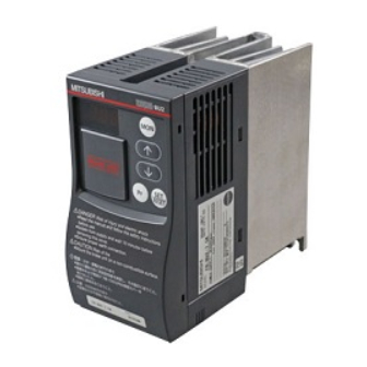
Rating plate Operation MITSUBISHI BRAKE UNIT panel MODEL FR-BU2-15K for 200V class INVERTER SERIAL : XXXX Front MITSUBISHI ELECTRIC CORPORATION cover MADE IN JAPAN MODEL FR-BU2- H □□K Applied motor Applied power capacity (kW) supply voltage 200V class Not used... -
Page 9: Installation
INSTALLATION INSTALLATION Enclosure surface mounting Encasing multiple brake units Remove the front cover and wiring cover to fix the brake unit to the surface. When encasing multiple brake units, install them in parallel as a cooling Leave enough clearances as measure. - Page 10 INSTALLATION The brake unit consists of precision mechanical and electronic parts. Never • install or handle it in any of the following conditions as doing so could cause an operation fault or failure. Vibration Horizontal High temperature, (5.9m/s or more) placement high humidity Direct sunlight...
-
Page 11: Wiring
WIRING WIRING 3.1 Terminals 3.1.1 Brake unit Terminal Symbol Terminal Name Description Rating Brake unit input Connect to the inverter terminal terminal P and N. Resistor connection Connect the brake resistor. terminal For earthing (grounding) the Earth (Ground) brake unit. Must be earthed (grounded). - Page 12 WIRING Terminal Symbol Terminal Name Description Rating When connecting the transistor output (open collector output), such as a programmable controller (PLC), connect the External positive external power supply transistor for transistor output to this common, terminal to prevent a Contact input malfunction caused by common undesirable currents.
- Page 13 PVC cables, Circuit Tightening Terminal Brake Unit Type Terminal Torque etc. (mm etc. (mm Screw • Size P/+, PR P/+, PR P/+, PR P/+, PR FR-BU2-1.5K/ 3.7K FR-BU2-7.5K 5.5-4 FR-BU2-15K 5.5-4 FR-BU2-30K 5.5-5 FR-BU2-55K 14-6 FR-BU2-H7.5K FR-BU2-H15K 5.5-4 FR-BU2-H30K 5.5-4 FR-BU2-H55K 5.5-5...
- Page 14 WIRING Control circuit terminal layout • SD SD MSGMSG Jumper Cable stripping size Loosen the terminal screw and insert the cable into the terminal. Screw size : M3 Wire the stripped cable Tightening torque : 0.5N m to 0.6N • •...
- Page 15 WIRING Changing the control logic • The input signals are set to sink logic when shipped from the factory. To change the control logic, the jumper connector under the control panel must be moved to the other position. Change the jumper connector in •...
- Page 16 WIRING 1) Sink logic type In sink logic, a signal switches on when a current flows from the • corresponding signal input terminal. Terminal SD is common to the contact input signals. Power supply Connecting a positive terminal of AY40 type •...
- Page 17 WIRING 2) Source logic type In this logic, a signal switches on when a current flows into the • corresponding signal input terminal. Terminal PC is common to the contact input signals. Power supply BUE Connecting a 0V terminal of the •...
-
Page 18: Resistor Unit
WIRING 3.1.2 Resistor unit (1) FR-BR-(H) Terminal Terminal Name Description Rating Symbol Main Resistor unit Connect to terminal P and PR of the brake circuit input resistance unit. 1NC contact Control Alarm output Output signal indicates resistor overheart 110VAC, 5A circuit terminal 220VAC, 3A... - Page 19 WIRING (2) MT-BR5 Terminal Terminal Name Description Rating Symbol Resistor unit Connect to terminal P and PR of the input terminal brake unit. Main circuit For earthing (grounding) of the resistor unit. Must be Earth terminal earthed (grounded). 1 NO contact, Alarm output Output signal indicates resistor Control...
-
Page 20: Combinations Of Brake Resistors For Brake Unit And Used Wires
3.2 Combinations of Brake Resistors for Brake Unit and Used Wires Brake Resistor, Resistor Brake Unit Type Cable Size (mm Unit Type FR-BU2-1.5K GZG 300W-50Ω (one) FR-BU2-3.7K GRZG 200-10Ω (three in series) FR-BU2-7.5K GRZG 300-5Ω (four in series) GRZG 400-2Ω (six in series) -
Page 21: External Connection Diagram
WIRING 3.3 External Connection Diagram 3.3.1 Connection with the inverter Inverter MCCB Three Motor R/L1 Resistor phase unit S/L2 power T/L3 supply Alarm output Reset brake permission signal Signal for master/slave Brake unit FR-BU2 When using the FR-BU2 with the FR-A500, A700 series 7.5K or less or FR-V500 series 5.5K or less, be sure to remove a jumper across terminal PR and PX. - Page 22 WIRING Connection method and parameter setting differ depending on the brake resistor and resistor unit to be used with. Refer to the page below depending on the brake resistor and resistor unit to be used with and their application. Refer to Page Brake Resistor, Application Resistor Unit...
-
Page 23: Connection Example With The Grzg Type Brake Resitor
WIRING 3.4 Connection Example with the GRZG Type Brake Resitor GRZG Configure a sequence which shuts off power when the brake unit outputs an alarm to prevent burnout due to the temperature rise of the brake resistor in case the transistor inside the brake unit is damaged. In addition, it is recommended to configure a sequence which shuts off power in the input side by the external thermal relay connected to the brake resistor. - Page 24 Even when the wiring is twisted, the cable length must not exceed 10m. It is recommended to install an external thermal relay to prevent overheat of brake resistors. <Recommended external thermal relay> Recommended External Brake Unit Brake Resistor Thermal Relay FR-BU2-1.5K GZG 300W-50Ω TH-N20 1.3A FR-BU2-3.7K GRZG 200-10Ω TH-N20 3.6A FR-BU2-7.5K GRZG 300-5Ω...
-
Page 25: When Connecting Several Brake Units To One Inverter
WIRING 3.4.2 When connecting several brake units to one inverter GRZG GRZG type brake registor MCCB Three Motor phase R/L1 External thermal S/L2 relay power T/L3 supply FR-BU2 Inverter 5m or less GRZG type brake registor External thermal relay FR-BU2 Connect the inverter terminals (P/+, N/-) and brake unit (FR-BU2) terminals so that their terminal names match with each other. -
Page 26: Master/Slave Operation When Connecting Several Brake Units
WIRING 3.4.3 Master/slave operation when connecting several brake units GRZG ⇔ slave operation (10 units maximum) Parallel operation by master When several units are conected, make sure to connect a signal cable to terminals (MSG, SD) for master/slave to operate. Three MCCB Motor... - Page 27 WIRING CAUTION To emphasize connection of master/slave operation in this diagram, other • connections are not shown. When actually connecting units, configure a circuit which prevents resistor overheat as shown in a connection example "When connecting several brake units to one inverter" on page 18 To replace the existing BU type brake unit, set "1"...
-
Page 28: Fr-Br-(H) Connection Example With Resistor Unit
WIRING 3.5 FR-BR-(H) Connection Example with Resistor Unit FR-BR Make up a sequence which always shuts off power in the input side by an overheat signal of the built-in thermal relay of the resistor unit in case a built- in transistor of the brake unit is damaged and configure a circuit which prevents the brake resistor from abnormal overheating, leading to burnout. -
Page 29: When Connecting Several Brake Units To One Inverter
WIRING 3.5.2 When connecting several brake units to one inverter FR-BR FR-BR MCCB Three Motor R/L1 phase S/L2 power T/L3 supply FR-BU2 Inverter 5m or less FR-BR FR-BU2 Connect the inverter terminals (P/+, N/-) and brake unit (FR-BU2) terminals so that their terminal names match with each other. -
Page 30: Master/Slave Operation When Connecting Several Brake Units
WIRING 3.5.3 Master/slave operation when connecting several brake units FR-BR ⇔ slave operation (10 units maximum) Parallel operation by master When several units are conected, make sure to connect a signal cable to terminals (MSG, SD) for master/slave to operate. MCCB Three Motor... -
Page 31: Connection Example With Mt-Br5 Type Resistor Unit
WIRING 3.6 Connection Example with MT-BR5 Type Resistor Unit MT-BR5 Make up a sequence which always shuts off power in the input side by an overheat signal of the built-in thermal relay of the resistor unit in case a built- in transistor of the brake unit is damaged and configure a circuit which prevents abnormal overheat of the brake resistor leading to burnout. -
Page 32: When Connecting Several Brake Units To One Inverter
WIRING 3.6.2 When connecting several brake units to one inverter MT-BR5 Three CR1 CR2 MCCB Motor phase R/L1 S/L2 power T/L3 supply 5m or less Inverter Registor unit MT-BR5 Brake unit FR-BU2 Connect the inverter terminals (P/+, N/-) and brake unit (FR-BU2) terminals so that their terminal names match with each other. -
Page 33: Master/Slave Operation When Connecting Several Brake Units
WIRING 3.6.3 Master/slave operation when connecting several brake units MT-BR5 ⇔ slave operation (10 units maximum) Parallel operation by master When several units are conected, make sure to connect a signal cable to terminals (MSG, SD) for master/slave to operate. Three MCCB Motor... - Page 34 WIRING CAUTION • To emphasize connection of master/slave operation in this diagram, other connections are not shown. When actually connecting units, configure a circuit which prevents resistor overheat as shown in a connection example "When connecting several brake units to one inverter" on page 25 . •...
-
Page 35: Wiring Instructions
WIRING 3.7 Wiring Instructions (1) When using this brake unit with the FR-A500, A700 series inverter 7.5K or less or FR-V500 series inverter 5.5K or less, be sure to remove a jumper across terminal PR and PX. (A failure to do so may damage a built-in brake resistor.) (2) Correctly connect the terminals P/+, N/- of the brake unit and terminals P, N of the inverter. - Page 36 WIRING (5) When connecting the FR-BEL power factor improving DC reactor, the brake unit terminal P/+ must be connected to the inverter. Accidental connection to P1 terminal may damage the brake unit. FR-BU2 FR-BU2 N/- P/+ PR N/- P/+ PR Inverter Inverter FR-BEL...
-
Page 37: Operation
OPERATION OPERATION 4.1 Control Panel Monitor (3-digit LED) Monitor display (use Pr.1 to change) Parameter setting Alarm display Operation key (refer to the table below) BRAKE UNIT Description Use this key to switch between the monitor display and alarm history display. -
Page 38: Basic Operation
OPERATION 4.2 Basic Operation At powering on Flickers during reset Monitor mode Parameter setting mode Regeneration Parameter status display number display Alarm history mode Past four alarms history The latest alarm is ended by "." Current setting value display flickers Flicker When no alarm exists, "... -
Page 39: Parameter List
OPERATION 4.3 Parameter List Minimum Para- Initial Setting Reference Name Setting meter Value Range Page Increments Brake mode switchover 0 to 2 Monitor display data 0 to 5 selection Input terminal function selection 1 (RES) 0 to 3 Input terminal function selection 2 (BUE) Parameter write selection 0, 1... -
Page 40: Mode Switchover (Pr.0)
Brake mode switchover BU mode MT-BU5 mode Available with the FR-BU2-1.5K to 15K and FR-BU2-H7.5K to H30K only. Available with the FR-BU2-55K and FR-BU2-H75K only. Perform the above parameter setting only when the inverter is at a stop. (1) FR-BU2 mode (setting value "0" (initial value)) -
Page 41: Multi-Function Monitor Display (Pr.1, Pr.78)
OPERATION 4.3.2 Multi-function monitor display (Pr.1, Pr.78) Select the monitor to be displayed on the operation panel. Parameter Initial Setting Name Description Remarks Number Value Range Regeneration status display DC bus voltage (V) DC bus voltage peak value (V) Energization time from shipment of the brake unit is Cumulative... - Page 42 OPERATION (1) Monitor description list (Pr. 1) Incre Pr.1 Monitor item Description ments setting Regeneration Indicates the ratio of brake unit operation during the status display specified time DC bus voltage DC bus voltage is displayed. DC current Holds the peak value of the DC bus voltage monitor voltage peak Pr.1 ="1").
-
Page 43: Input Terminal Function Selecttion (Pr.2, Pr.3)
OPERATION 4.3.3 Input terminal function selecttion (Pr.2, Pr.3) Use these parameters to select/change the input terminal functions. Parameter Initial Setting Name Description Number Value Range Input terminal function seleciton 1 (RES) 0 to 3 Refer to the following table Input terminal function seleciton 2 (BUE) A jumper is connected across terminal RES and SD in the initial setting. -
Page 44: Parameter Write Disable Selection (Pr. 77)
OPERATION 4.3.4 Parameter write disable selection (Pr. 77) You can select whether write to various parameters can be performed or not. Use this function to prevent parameter values from being rewritten by misoperation. Parameter Initial Setting Name Description Number Value Range Parameter write is always Parameter write... -
Page 45: Parameter Clear
OPERATION 4.3.5 Parameter clear POINT Set "1" in CLr All parameter clear to initialize all parameters. • Parameters are not cleared when "1" is set in Pr. 77 Parameter write selection . Operation Display Screen at powering on The mode is changed to monitor mode. -
Page 46: Alarm History Clear
OPERATION 4.3.6 Alarm history clear POINT Set "1"in to clear alarm history. ECL Alarm history clear Operation Display Screen at powering on The mode is changed to monitor mode. Press to choose the The parameter number read parameter setting mode. previously appears. -
Page 47: Protective Functions
PROTECTIVE FUNCTIONS PROTECTIVE FUNCTIONS 5.1 Causes and Corrective Actions Error Message • A message regarding operational troubles is displayed. Output is not shutoff. Operation panel indication Name Write disable error You attempted to make parameter setting when Pr. 77 Parameter write Description selection has been set to disable parameter write. - Page 48 PROTECTIVE FUNCTIONS Operation panel indication Name Brake transistor alarm detection This function stops the inverter output if an alarm occurs in the brake circuit, Description e.g. damaged brake transistors. • Reduce the load inertia. • Check that the frequency of using the brake is proper. Check point •...
-
Page 49: Correspondence Between Digital And Actual Characters
PROTECTIVE FUNCTIONS 5.2 Correspondence Between Digital and Actual Characters There are the following correspondences between the actual alphanumeric characters and the digital characters displayed on the operation panel: Actual Indication Actual Indication Actual Indication... -
Page 50: Specifications
SPECIFICATIONS SPECIFICATIONS 6.1 Brake Unit Specifications 200V 400V Type FR-BU2- 1.5K 3.7K 7.5K H7.5K H15K H30K H55K H75K Applicable motor Capacity of the motor to be used with differs according to the braking torque and capacity duty (%ED) Connected brake GRZG type, FR-BR type, MT-BR5 type resistance 10 units maximum... -
Page 51: Precautions For Maintenance And Inspection
PRECAUTIONS FOR MAINTENANCE AND INSPECTION PRECAUTIONS FOR MAINTENANCE AND INSPECTION The brake unit is a static unit mainly consisting of semiconductor devices. Daily inspection must be performed to prevent any fault from occurring due to the adverse effects of the operating environment, such as temperature, humidity, dust, dirt and vibration, changes in the parts with time, service life, and other factors. -
Page 52: Periodic Inspection
PRECAUTIONS FOR MAINTENANCE AND INSPECTION 7.3 Periodic Inspection Check the areas inaccessible during operation and requiring periodic inspection. Consult us for periodic inspection. Cooling system fault ......Clean the air filter, etc. Tightening check and retightening ..The screws and bolts may become loose due to vibration, temperature changes, etc. -
Page 53: Daily And Periodic Inspection
PRECAUTIONS FOR MAINTENANCE AND INSPECTION 7.4 Daily and Periodic Inspection Interval Corrective Action Custo- Inspection Item Description at Alarm mer's Occurrence Check Check the ambient temperature, Surrounding Improve humidity, dirt, corrosive gas, oil mist , environment environment. etc. Check alarm Check for unusual vibration and Overall unit location and... -
Page 54: Replacement Of Parts
° and 365 days a year in the average yearly ambient temperature of 40 CAUTION For parts replacement, consult the nearest Mitsubishi FA Center. (1) Smoothing capacitors An aluminum electrolytic capacitor is used for stabilizing the control power in the control circuit. The characteristics is deteriorated by the adverse effects of ripple currents, etc. -
Page 55: Selection
1) Select the brake unit according to the motor capacity. 2) To obtain the braking torque not less than 200%, use a larger inverter in capacity. <GZG, GRZG type are connected> Motor (kW) 0.75 Braking Torque 50%30s FR-BU2-1.5K FR-BU2-3.7K FR-BU2-7.5K FR-BU2- 100%30s FR-BU2-1.5K FR-BU2-7.5K FR-BU2-15K 3.7K 50%30s FR-BU2-H7.5K... - Page 56 SELECTION <When FR-BR is connected> %ED at short-time rating when braking torque is 100% • 18.5 Motor Capacity FR-BU2-15K FR-BU2-30K FR-BU2-55K FR-BU2-H15K FR-BU2-H30K FR-BU2-H55K Braking torque (%) at short-time rating of 15s • 18.5 Motor Capacity Bra- FR-BU2-15K king FR-BU2-30K torque FR-BU2-55K FR-BU2-H15K Bra-...
- Page 57 SELECTION <MT-BR5 is connected> ED at short-time rating when braking torque is 100% • Motor Capacity FR-BU2-55K × FR-BU2-55K FR-BU2-H75K × FR-BU2-H75K × FR-BU2-H75K × FR-BU2-H75K × FR-BU2-H75K Braking torque (%) at short-time rating of 15s • Motor Capacity FR-BU2-55K ×...
-
Page 58: Outline Dimension Drawings
OUTLINE DIMENSION DRAWINGS OUTLINE DIMENSION DRAWINGS (1) Brake Unit FR-BU2-1.5K to 15K • FR-BU2-H7.5K, H15K 5 hole (Screw size: M4) BRAKE UNIT Rating plate 18.5 132.5 (Unit: mm) FR-BU2-30K • FR-BU2-H30K 5 hole (Screw size: M4) BRAKE UNIT Rating plate 18.5... - Page 59 OUTLINE DIMENSION DRAWINGS FR-BU2-55K • FR-BU2-H55K, H75K 5 hole (Screw size: M4) BRAKE UNIT Rating plate 18.5 142.5 (Unit: mm)
- Page 60 OUTLINE DIMENSION DRAWINGS (2) Resistor unit <GRZG type> d hole Terminal (Unit: mm) Model GZG300W GRZG200 GRZG300 GRZG400 The maximum temperature rise of the brake resistors is approximately • 200deg or more. For wiring, therefore, use heat-resistant wires (such as fiber-glass braided wires) or cover the wires with silicone tube.
- Page 61 OUTLINE DIMENSION DRAWINGS <FR-BR type> Control circuit terminal Main circuit terminal (35) W1 1 (35) The FR-BR-55K and H55K are provided with two eyebolts. (see below) Eyebolt (Unit: mm) Approximate Resistor Unit Type Mass (kg) FR-BR-15K 170 100 450 410 432 220 3.2 FR-BR-30K 340 270 600 560...
- Page 62 OUTLINE DIMENSION DRAWINGS <MT-BR5 type> 4 15 installation hole (Unit: mm) Be sure to select the well-ventilated place for installation of the resistor unit. Ventilation is necessary when installing the resistor in a place, e.g. enclosure, where heat is not well diffused. The temperature rise of the resistor unit is 300deg.
-
Page 63: Instructions For Ul, Csa Standard Compliance
INSTRUCTIONS FOR UL, CSA STANDARD COMPLIANCE INSTRUCTIONS FOR UL, CSA STANDARD COMPLIANCE Instructions for UL, CSA standard compliance (UL mark is printed on UL qualified products) 1. UL standard UL standard is the general standard of motor control devices in the United States. - Page 64 MEMO...
- Page 65 REVISIONS *The manual number is given on the bottom left of the back cover. Print Date *Manual Number Revision Sep., 2006 IB(NA)-0600292ENG-A First edition...
Need help?
Do you have a question about the FR-BU2-1.5K and is the answer not in the manual?
Questions and answers