Sign In
Upload
Manuals
Brands
Mitsubishi Manuals
Inverter
700 Series
Mitsubishi 700 Series Manuals
Manuals and User Guides for Mitsubishi 700 Series. We have
2
Mitsubishi 700 Series manuals available for free PDF download: Instruction Manual
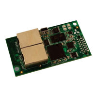
Mitsubishi 700 Series Instruction Manual (280 pages)
Plug-in option. Ethernet multiprotocol communication interface
Brand:
Mitsubishi
| Category:
Inverter
| Size: 14.88 MB
Table of Contents
Table of Contents
4
1 Pre-Operation Instructions
14
Product Overview
14
Features and Specifications
16
Configuration Studio
16
Inverter Compatibility
31
November
32
Unpacking and Product Confirmation
33
Shipment Confirmation
33
Component Overview
35
LED Indicators
36
Port Status LED Description
36
Standard LED Description
37
Ethercat LED Description
38
2 Installation
40
Pre-Installation Instructions
40
A700 & F700 Installation Procedure
42
Installation of the Communication Option LED Display Cover
42
Installation of the Communication Option on Control Board
43
E700 Installation Procedure
45
Wiring
46
3 Inverter Settings
47
Network Setting
48
Operation Mode Setting
50
Operation Mode Indication
50
Operation Mode Switching & Comm. Startup Mode (Pr. 79, Pr. 340)
51
Operation & Speed Command Source (Pr. 338, Pr. 339, Pr. 550)
55
Communication EEPROM Write Selection (Pr. 342)
59
4 Register Numbering and Behavior
60
Register Numbers
60
Scanned Registers
63
Inverter Command Register
65
Frequency Command Register
66
Operation Mode Register
67
Inverter Reset Register
67
Alarm History Clear Register
68
All Parameter Clear Register
68
Inverter Status Register
69
Operation Mode Status Register
70
Alarm History Codes
70
5 Mitsubishi Configuration Studio
71
Overview
71
General Object Editing Activities
76
Ethernet Settings
79
Authentication
79
Network Configuration
80
Internal Logic Settings
80
Fail-Safe Values
80
Overview
80
Timeout Time
81
Timeout Object Configuration
81
Discovery over Ethernet
83
Manage Device Parameters
84
Backup and Restore Parameters
86
Restore Factory Settings
89
Diagnostic Object
89
Help
90
6 Embedded Web Server
91
Overview
91
Monitor Tab
93
Information Window
93
Parameter Group Selection List
93
Parameter List
94
Parameter List Filter
96
Radix Selection
96
Dashboard Tab
98
Information Window
99
Gauge Window Navigation
99
Gauge Window Configuration
100
Submitting Changes
105
Customizing the Embedded Web Server
106
Customization Overview
106
Xtpro Overview
107
Xtpro Web Browser-Based Implementation
107
Xtpro HMI-Based Implementation
109
Xtpro Supported Commands
110
7 Filesystem
111
Overview
111
USB with Windows Explorer
112
FTP with Windows Explorer
113
Loading New Web Server Content
115
8 Firmware
116
Overview
116
Update Procedure
116
9 Protocol-Specific Information
118
Modbus/Tcp Server
118
Overview
118
Holding & Input Registers
119
Coil & Discrete Input Mappings
120
Connection Timeout Options
121
Node Settings
123
Holding/Input Register Remap Settings
123
Ethernet/Ip Server
125
Overview
125
Server Settings
127
Connection Timeout Options
127
Generic Class 1 I/O Produced and Consumed Data Settings
129
Generic Class 1 (I/O) Connection Access
131
AC/DC Drive Profile Class 1 (I/O) Connection Access
131
Explicit Messaging Via Get/Set Attribute Single Services
138
Explicit Messaging Via Data Table Read/Write Services
139
Inverter Register Access Tag Format
139
Controllogix Examples: Setup
141
Controllogix Example: EDS Add-On Profile (AOP)
142
Controllogix Example: EDS Add-On Profile (AOP) Generic I/O Messaging
148
Controllogix Example: EDS Add-On Profile (AOP) AC/DC Drive Profile
151
Controllogix Example: I/O Messaging
154
Controllogix Example: Generic Default I/O Add-On Instruction
159
Controllogix Example: AC/DC Drive Profile Add-On Instruction
162
Controllogix Example: Read Registers
166
Controllogix Example: Reading and Writing Multiple MSG Instructions
172
Allen Bradley CSP (PCCC) Server
175
Overview
175
Explicit Messaging Via Read/Write Services
175
Inverter Register File Number Offset Format
176
SLC-5/05 Example: Read Registers
179
SLC-5/05 Example: Reading and Writing
186
Bacnet/Ip Server
188
Protocol Implementation Conformance Statement
188
Default Supported Objects
198
Default Supported Object Details
202
Server Settings
206
Node Settings
206
Device Object Settings
206
Bacnet Object Settings
207
Analog Input Object Settings
207
Analog Output Object Settings
208
Analog Value Object Settings
209
Binary Input Object Settings
210
Binary Output Object Settings
212
Binary Value Object Settings
214
Multi-State Input Object Settings
216
Multi-State Output Object Settings
216
Multi-State Value Object Settings
217
MELSEC / SLMP Server
218
Overview
218
Read/Write Commands
219
Server Settings
220
Connection Timeout Options
221
CC-Link IE Field Basic Server
223
Overview
223
Server Settings
223
Produced and Consumed Data Settings
224
MELSEC Client
227
Overview
227
Read/Write Commands
228
Connection Timeout Options
228
Remote Device Settings
229
Command and Monitor Data Object Settings
230
Diagnostic Objects
232
SLMP Client
233
Overview
233
Read/Write Commands
234
Connection Timeout Options
234
Remote Device Settings
235
Command and Monitor Data Object Settings
236
Diagnostic Objects
238
Profinet Io
239
Overview
239
Device Settings
240
Connection Timeout Options
240
Cyclic I/O Produced and Consumed Data Access Settings
241
Profidrive Profile
244
Profidrive Standard Telegram 1
244
Profidrive Control and Status Words
245
Profidrive Reference Speed Setpoint and Actual Speed
249
Profidrive-Specific Parameters
252
Profidrive State Diagram
253
Acyclic Data Access
254
TIA Portal (STEP 7) Hardware Configuration Example
254
Register the GSDML File
254
Add the Device to the Configuration
256
Select the IO Controller
257
Assign the I/O Module
257
Configure the Device Properties
258
Online Device Discovery and Configuration
261
Save the Configuration
263
GE Proficy Configuration Example
263
Register the GSDML File
263
Add the Device to the Configuration
265
Configure the Device Properties
267
Save the Configuration
268
IEC 61850 Server
269
Overview
269
Server Settings
269
GOOSE Communication Parameters
270
Generic Process I/O Status and Control Object Settings
271
Ethercat Slave
273
Overview
273
Device Settings
273
Transmit and Receive Process Data Word Settings
274
10 Troubleshooting
276
Advertisement
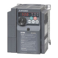
Mitsubishi 700 Series Instruction Manual (147 pages)
Brand:
Mitsubishi
| Category:
Inverter
| Size: 13.73 MB
Table of Contents
Table of Contents
5
Product Checking and Parts Identification
10
2 Installation and Wiring
11
Peripheral Devices
12
Removal and Reinstallation of the Cover
13
Front Cover
13
Wiring Cover
15
Installation of the Inverter and Instructions
16
Installation of the Inverter and Instructions
17
Wiring
18
Terminal Connection Diagram
18
Specification of Main Circuit Terminal
19
Terminal Arrangement of the Main Circuit Terminal, Power Supply and the Motor Wiring
19
Control Circuit Terminal
24
Changing the Control Logic
26
Wiring of Control Circuit
28
Safety Stop Function
31
Connection to the PU Connector
33
When Using the Brake Resistor (MRS Type, MYS Type, FR-ABR)
35
Power-OFF and Magnetic Contactor (MC)
36
Precautions for Use of the Inverter
37
Failsafe of the System Which Uses the Inverter
39
3 Drive the Motor
40
Step of Operation
40
Operation Panel
41
Names and Functions of the Operation Panel
41
Basic Operation (Factory Setting)
42
Easy Operation Mode Setting (Easy Setting Mode)
43
Operation Lock (Press [MODE] for a While (2S))
44
Monitoring of Output Current and Output Voltage
45
First Priority Monitor
45
Setting Dial Push
45
Changing the Parameter Setting Value
46
Parameter Clear/All Parameter Clear
47
Initial Value Change List
48
Before Operation
49
Simple Mode Parameter List
49
Overheat Protection of the Motor by the Inverter (Pr. 9)
50
When the Rated Motor Frequency Is 50Hz (Pr. 3)
52
Increasing the Starting Torque (Pr. 0)
53
Setting the Maximum and Minimum Output Frequency (Pr. 1, Pr. 2)
54
Changing Acceleration and Deceleration Time of the Motor (Pr. 7, Pr. 8)
55
Selection of the Start Command and Frequency Command Locations (Pr. 79)
56
Acquiring Large Starting Torque and Low Speed Torque (General-Purpose Magnetic Flux Vector Control (Pr. 71, Pr. 80))
57
Exhibiting the Best Performance for the Motor (Offline Auto Tuning) (Pr. 71, Pr. 80, Pr. 82 to Pr. 84, Pr. 90, Pr. 96)
59
Start/Stop from the Operation Panel (PU Operation)
63
Setting the Frequency by the Operation Panel
63
Using the Setting Dial Like a Potentiometer to Perform Operation
65
Setting the Frequency by Switches (Three-Speed Setting) (Pr. 4 to Pr. 6)
66
Setting the Frequency by Analog Input (Voltage Input)
68
Setting the Frequency by Analog Input (Current Input)
69
Make a Start and Stop with Terminals (External Operation)
71
Setting the Frequency by the Operation Panel (Pr. 79 = 3)
71
Setting the Frequency by Switches (Three-Speed Setting) (Pr. 4 to Pr. 6)
73
Setting the Frequency by Analog Input (Voltage Input)
75
Changing the Output Frequency (60Hz, Initial Value) at the Maximum Voltage Input (5V, Initial Value)
77
Setting the Frequency by Analog Input (Current Input)
78
Changing the Output Frequency (60Hz, Initial Value) at the Maximum Current Input (at 20Ma, Initial Value)
80
Parameter List
81
List of Parameters Classified by the Purpose
81
Displaying the Extended Parameters
83
Parameter List
84
4 Troubleshooting
105
Reset Method of Protective Function
105
List of Fault or Alarm Indications
106
Causes and Corrective Actions
107
Correspondences between Digital and Actual Characters
116
Check and Clear of the Faults History
117
Check First When You Have a Trouble
119
Motor Does Not Start
119
Motor or Machine Is Making Abnormal Acoustic Noise
121
Inverter Generates Abnormal Noise
122
Motor Generates Heat Abnormally
122
Motor Rotates in the Opposite Direction
122
Speed Greatly Differs from the Setting
122
Acceleration/Deceleration Is Not Smooth
123
Speed Varies During Operation
123
Operation Mode Is Not Changed Properly
124
Operation Panel Display Is Not Operating
124
Motor Current Is too Large
124
Speed Does Not Accelerate
125
Unable to Write Parameter Setting
125
Inspection Items
126
Daily Inspection
126
Periodic Inspection
126
Daily and Periodic Inspection
127
Display of the Life of the Inverter Parts
128
Cleaning
130
Replacement of Parts
130
5 Precautions for Maintenance and Inspection
126
Rating
134
6 Specifications
134
Common Specifications
136
Outline Dimension Drawings
137
Appendix
140
Motor Overload Protection
145
Advertisement
Related Products
Mitsubishi 73
Mitsubishi 738 Series
Mitsubishi 750 SB
Mitsubishi Diamond Scan 72 M700
Mitsubishi DPLUS 74SB -BKB
Mitsubishi Diamond Pro 700 TFK9705SKHKW
Mitsubishi Diamond Scan 70 SD7714C
Mitsubishi Diamond Scan 70 SD7714CM
Mitsubishi FDCW 71VNX
Mitsubishi 7011A SERIES
Mitsubishi Categories
Air Conditioner
Controller
Projector
Automobile
Engine
More Mitsubishi Manuals
Login
Sign In
OR
Sign in with Facebook
Sign in with Google
Upload manual
Upload from disk
Upload from URL