Table of Contents
Advertisement
Advertisement
Table of Contents

Related Manuals for Mitsubishi FREQROL-E700


Summary of Contents for Mitsubishi FREQROL-E700
- Page 1 Satellite Training Series PART Your First Inverter...
-
Page 3: Safety Precautions
Take the following precautions and use the equipment correctly when practicing and learning the material. The Mitsubishi general-purpose inverter FR-E700 series is used for this training. If the equipment in your actual environment is different, make sure to read the specif- ic manual for your device as operation methods and parameter type differ depend- ing on the specific model of inverter. - Page 4 2. Fire prevention This section is specifically about safety matters Do not attempt to install, operate, maintain or inspect the inverter until you have read through the Instruction Manual and appended documents carefully and can use the equipment correctly. Do not ●...
- Page 5 (2) Wiring ● The inverter can be easily set for high-speed operation. Before changing its setting, the performances of the motor and ma- ● Do not install a power factor correction capacitor or surge sup- chine must be fully examined. pressor/capacitor type filter on the inverter output side.
- Page 6 This document covers some fundamentals of inverters that first-time users of inverters should know. This document was created on the premise that the Mitsubishi general-purpose inverter FR-E700 series would be used for training. Before wiring your inverter, make sure to read the related manuals of your products to ensure that you exercise appropriate caution with regards to safety.
-
Page 7: Table Of Contents
2.1 Mitsubishi general-purpose inverters ................... 2-2 2.1.1 Lineup ..........................2-2 2.2 Detailed description of the inverter ....................2-5 2.2.1 Parts identification for the Mitsubishi general-purpose inverter FR-E700 series ....2-5 2.3 Connecting the inverter........................ 2-6 2.3.1 Removing and installing the cover ..................2-6 2.3.2 Connecting the power cable .................... - Page 8 3.5 How to configure parameters....................... 3-8 3.5.1 Parameter clear/All parameter clear ................... 3-8 3.5.2 Pr. 9 Electronic thermal O/L relay ..................3-9 3.5.3 Pr. 3 Base frequency......................3-10 3.5.4 Pr. 0 Torque boost ......................3-11 3.5.5 Pr. 1, 2 Upper-limit/lower-limit frequency ................3-12 3.5.6 Pr.
- Page 9 5.2 Connecting MELSEC iQ-F series with the inverter ..............5-7 5.2.1 Function overview ....................... 5-7 5.2.2 System configuration ......................5-8 5.2.3 Connecting terminating resistors ..................5-10 5.2.4 Cable wiring diagram ......................5-11 5.2.5 Inverter communication settings ..................5-13 5.2.6 FX5 programmable controller communication settings ............. 5-14 5.3 External potentiometer operation....................
- Page 10 MEMO...
-
Page 11: Chapter 1 Brief Description Of Inverters
Inverter basics Chapter 1 Brief description of inverters Inverter basics As we will cover in more detail throughout this document, "inverters" are devices used to control motor speed. While this is not a term often heard in typical conversation, inverters are used in many of the devices used on a daily basis. -
Page 12: What Is An Inverter
1.1 What is an inverter? 1.1.1 Basic functions of the inverter ◎ Inverter Motors are used to operate many of the devices and products we use on a daily basis. The reason devices do not suddenly start to operate when power switches are turned on is because the inverter controls the speed of motors. -
Page 13: Familiar Examples Where Inverters Are Used
1.1.3 Familiar examples where inverters are used Belt conveyors used in factories ☆ Improve efficiency of work, braking at specific positions, automatic operation ● The inverter improves efficiency of work and enable conveyors to be stopped at specific positions. ● Conveyor speeds can be optimally adjusted depending on the work conditions. ●... - Page 14 Ventilation fans used in buildings ● Pump Damper control ● Fan, blower Damper Switch Standard motor ● Ventilation fan ● Cooling tower ● Drying machine (Furnace fan) Fan, blower Inverter control Inverter Standard motor Fan, blower ☆ The inverter achieves energy efficiency and automation. ●...
- Page 15 Inverters are used in these and many other applications. Electric vehicle Air conditioner Train Washing machine As you can see, inverters are used in the products and devices we use every day.
-
Page 16: Motor Drive Force
1.2 Motor drive force 1.2.1 Motor and frequency Motor speed is changed by varying the frequency of current flowing through motors. Frequency is discussed in more detail in this section. ◎ Frequency Outlets in homes, for example, supply power at 100V/50Hz and 200V/60Hz specifications. "V"... -
Page 17: Principles Of The Motor
1.2.2 Principles of the motor When a motor is connected to a source of power, current flows through the stator winding, or stator coil, within the motor, which creates a rotating magnetic field. This rotating magnetic field causes the stator (rotor) to rotate. Motor speed is proportional to the frequency of the power source. -
Page 18: Changing Frequency
1.3 Changing frequency 1.3.1 Structure of the inverter The inverter is generally comprised of 3 sections: converter section, inverter section, and control circuit. ◎ Converter section The converter section converts an AC of an AC power supply into a DC, and then smooths out the pulses of current by the smoothing capacitor. -
Page 19: Chapter 2 Specific Models Of The Inverter
Mitsubishi general-purpose inverters This chapter introduces several types of actual "inverters". Mitsubishi offers many types of inverters to suit different purposes. This chapter will cover the compact and high functionality FR-E700 model in detail. Make sure the power is not turned on before connecting the power cable. -
Page 20: Mitsubishi General-Purpose Inverters
2.1 Mitsubishi general-purpose inverters 2.1.1 Lineup Inverter line-up 500 (L) Vector inverter Advanced functionality and high-performance inverter Energy-saving premium inverter Compact and powerful inverter 700PJ Air conditioning inverter Simple and compact inverter Capacity Applicable series for each industry General industrial machine... - Page 21 For fans and pumps 0.75K to 110K Three-phase 200V class FR-F800 0.75K to 560K Three-phase 400V class ● Drives both the general-purpose motors and IPM motors. When it drives an IPM motor (MM-EFS), which has permanent magnets embedded in its rotor, energy savings and high efficiency can be further achieved.
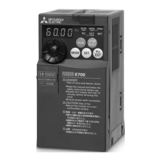
- Page 22 (Suitable for transfer, conveyor, food packaging, General industrial applications and standard machine tools, etc.) Single-phase 100V class 0.1K to 0.75K Three-phase 200V class 0.1K to 15K FR-E700 Single-phase 200V class 0.1K to 2.2K Three-phase 400V class 0.4K to 15K ● 0.5Hz 200% torque (0.1K to 3.7K) can be generated under Advanced magnetic flux vector control.
-
Page 23: Detailed Description Of The Inverter
2.2 Detailed description of the inverter 2.2.1 Parts identification for the Mitsubishi general-purpose inverter FR-E700 series ● Inverter model FR - E720 - 1.5 K Voltage class Symbol Control circuit terminal specification Represents the E720 Three-phase 200V class None Standard control circuit terminal (screw plug) -
Page 24: Connecting The Inverter
2.3 Connecting the inverter 2.3.1 Removing and installing the cover Removal Remove the front cover by pulling it toward you in the direction of arrow. Reinstallation To reinstall, match the cover to the inverter front and install it straight. Wiring cover Removes easily when pulled toward the front. -
Page 25: Connecting The Power Cable
2.3.2 Connecting the power cable There are two types of power cables that can be used to connect to the inverter. *Either the single-phase input type or three-phase input type cable is used depending on your power supply. The single-phase input type is also further separated in 200V and 100V inputs. The output in either case is three-phase at 200V. Single-phase two-wire power supply This power supply is used for home electric appliances and small electric equipment. -
Page 26: Control Terminals
2.3.3 Control terminals Terminal layout Terminal screw size M3: (Terminals A, B, and C) M2: (All others) 4 RUN FU SE STF STR Wiring method For the control circuit wiring, strip off the sheath of a cable and use as it is. Strip off the sheath about the size below. - Page 27 ● Blade terminals Strip the sheath off of wires, and connect them to a blade terminal. Strip off the sheath about the size below. If the length of the sheath peeled is too long, a short circuit may occur among neighboring wires. If the length is too short, wires might come off. Wire the stripped wire after twisting it to prevent it from becoming loose.
-
Page 28: Inverter Usage Precautions
2.4 Inverter usage precautions 2.4.1 Installation of the inverter Enclosure surface mounting Remove the front cover and wiring cover to fix the inverter to the surface. FR-E720-0.1K (SC) - 0.75K (SC) FR-E720-1.5K (SC) or later FR-E720S-0.1K (SC) - 0.4K (SC) FR-E740-0.4K (SC) or later FR-E710W-0.1K - 0.4K FR-E720S-0.75K (SC) or later... - Page 29 Installation orientation of the inverter Install the inverter on a wall as specified. Do not mount it horizontally or in any other way. Clearance around the inverter To ensure ease of heat dissipation and maintenance, leave at least the shown clearances around the inverter. At least the following clearances are required under the inverter as a wiring space, and above the inverter as a heat dissipation space.
- Page 30 Above inverter Heat is blown up from inside the inverter by the small fan built in the unit. Any equipment placed above the inverter should be heat resistant. Arrangement of multiple inverters When multiple inverters are placed in the same enclosure, generally arrange them horizontally as shown below in the figure (a).
-
Page 31: Troubleshooting
2.4.2 Troubleshooting When a fault occurs in the inverter, the inverter trips and the PU display automatically changes to one of the fol- lowing fault or alarm indications. ◎ Retention of fault output signal When the magnetic contactor (MC) provided on the input side of the inverter is opened when a fault occurs, the inverter's control power will be lost and the fault output will not be held. - Page 32 MEMO 2-14...
-
Page 33: Chapter 3 Parameters
Inverter basics Chapter 3 Parameters Inverter basics You must have an understanding of parameters in order to configure "inverters". We will use the belt conveyor example described in Chapter 1 again here. If the motor moving the belt conveyor is not rotated smoothly, items on the belt conveyor could fall off and break. -
Page 34: Setting Basic Parameters
3.1 Setting basic parameters 3.1.1 Brief description of parameters Parameters are the values used to configure inverter operation. These are notated as "Pr.". The type and num- ber of parameters available differ depending on inverter model. For simple variable-speed operation of the inverter, the initial values of the parameters may be used as they are. Configure the necessary parameters in accordance with loads and operational specifications. -
Page 35: Operation Panel
Used to stop Run command. Fault can be reset when protective function is activated (major fault). M Dial (M Dial: Mitsubishi inverter dial) Used to change the frequency setting Operation mode switchover and parameter values. Used to switch between the PU and Press to display the following. -
Page 36: Selecting The Operation Mode And Command Source
Control terminal External Programmable controller operation mode Switch POINT ● Mitsubishi Electric factory automation devices such as programmable controllers and GOTs are equipped with Mitsubishi general-purpose inverter protocols for easy integration by simply connecting cables and con- figuring communication settings. -
Page 37: Operation Mode Selection (Pr. 79)
3.3.2 Operation mode selection (Pr. 79) Used to select the operation mode of the inverter. Mode can be changed as desired among operation using ex- ternal command signals (External operation), operation from the operation panel and PU (FR-PU07/FR-PU04) (PU operation), combined operation of PU operation and External operation (External/PU combined operation), and Network operation (when RS-485 communication or a communication option is used). -
Page 38: Basic Operation Modes
3.4 Basic operation modes 3.4.1 External operation mode External operation mode is used to input start and frequency commands with external potentiometers and switches connected to the control circuit terminal. Inverter Forward rotation start Reverse rotation start Frequency setting potentiometer 3.4.2 PU operation mode PU operation mode is used to input start and frequency commands with operation panels or parameter units... -
Page 39: External/Pu Operation Mode 1
3.4.3 External/PU operation mode 1 Select the External/PU operation mode 1 when applying frequency command from the operation panel or parameter unit (FR-PU04/FRPU07) and inputting the start command with the external start switch. Inverter Forward Operation panel rotation start Reverse rotation start 3.4.4 External/PU operation mode 2 Select the External/PU operation mode 2 to input... -
Page 40: How To Configure Parameters
3.5 How to configure parameters 3.5.1 Parameter clear/All parameter clear Parameter settings may have been changed if the inverter is used. Use this procedure to restore parameters to their initial values. Operation Display Screen at power-ON The monitor display appears. Changing the operation mode PU indication is lit. -
Page 41: Pr. 9 Electronic Thermal O/L Relay
3.5.2 Pr. 9 Electronic thermal O/L relay Configure the current value for the electronic thermal O/L relay to enable motor overheating protection. This can help you achieve optimal protection capability for various operating conditions such as low-speed operation and reduced motor cooling capacity. Name Initial value Setting range... -
Page 42: Pr. 3 Base Frequency
3.5.3 Pr. 3 Base frequency Use this function to adjust the inverter output (voltage, frequency) to match the motor rating. Name Initial value Setting range Description Rated motor frequency. Base frequency 60Hz 0 to 400Hz (50Hz/60Hz) ● When operating a standard motor, generally set the rated frequency of the motor to Pr. 3 Base frequency. When running the motor using commercial power supply-inverter switch-over operation, set Pr. -
Page 43: Pr. 0 Torque Boost
3.5.4 Pr. 0 Torque boost This parameter is used to correct voltage drops in low-frequency ranges and improve decreases in motor torque during low speeds. • Motor torque during low-frequency ranges can be adjusted in accordance with load and can be increased during startup. Name Initial value Setting range... -
Page 44: Pr. 1, 2 Upper-Limit/Lower-Limit Frequency
3.5.5 Pr. 1, 2 Upper-limit/lower-limit frequency These parameters can be used to restrict motor speed. These parameters are used to set upper and lower limits on output frequency. Name Initial value Setting range Description Upper-limit frequency 120Hz 0 to 120Hz Upper limit of the output frequency Lower-limit frequency 0 to 120Hz... -
Page 45: Pr. 7, 8 Acceleration/Deceleration Time
3.5.6 Pr. 7, 8 Acceleration/deceleration time These parameters are used to configure the motor acceleration/deceleration time. Set larger values for slower acceleration/deceleration and smaller values for faster acceleration/deceleration. Name Initial value Setting range Description 3.7K or less Acceleration time 5.5K, 7.5K 0 to 3600/360s Motor acceleration time 11K, 15K... - Page 46 MEMO 3-14...
-
Page 47: Chapter 4 How To Use Fr Configurator
Controlling inverters using a PC Chapter 4 How to use FR Configurator Using FR Configurator makes parameter configuration even easier. Many parameters can be configured in single batch operations with the software "FR Configurator". This chapter will cover how to connect the inverter to a PC, Easy Setup, and finally basic operation of the software. -
Page 48: Fundamental Knowledge To Operate Fr Configurator
4.1 Fundamental knowledge to operate FR Configurator 4.1.1 Items needed for connectivity Inverter PC (FR Configurator) USB cable 4.1.2 Connection method All you need to connect a PC and inverter is a single USB cable. Only peer-to-peer connections can be established. -
Page 49: Startup
4.1.3 Startup The "Startup" window is displayed when FR Configurator is started. Each function can be directly selected from the "Startup" window. Name Function and description Shows up to five recent used files. Open Point a cursor on "Open", and five recent used files are shown. Click the file name, then "Startup"... -
Page 50: Screen Configuration (Main Frame)
4.1.4 Screen configuration (Main frame) The Main frame (main window) of FR Configurator consists of three areas. • Navigation area An area for showing information of the registered inverter, or for making settings. "Test Operation", "System Settings", "Setting Wizard", and "Troubleshooting" are available in this area. •... -
Page 51: Screen Configuration (Navigation Area)
4.1.5 Screen configuration (Navigation area) The Navigation area is for showing registered inverter information, switching of operation mode and ONLINE/ OFFLINE, sending of start/stop command, changing of the set frequency, or starting Setting Wizard. "Test Operation", "System Settings", "Troubleshooting" and "Setting Wizard" are available in this area. The Upper part of the Navigation area displays "Test Operation", and the lower part displays "System View". -
Page 52: Screen Configuration (System Area)
4.1.6 Screen configuration (System area) The System area is for showing and reading/writing parameters, or for diagnosis and converting from parameter setting of conventional model. "Parameter List", "Diagnosis", and "Convert" are available in this area. Select [Parameter List], [Diagnosis], or [Convert] under [View] menu, or click icons on the tool bar to switch the function displayed in the System area. -
Page 53: Screen Configuration (Monitor Area)
4.1.7 Screen configuration (Monitor area) Monitor area is for showing obtained monitor data of inverter. "Graph", "I/O Terminal Monitor", "Machine Analyzer", and "Batch Monitor" are available in this area. Select [Graph], [Machine Analyzer], [Batch Monitor], or [I/O Terminal Monitor] under [View] menu, or click an icon on the tool bar to display the function in Monitor area. -
Page 54: Easy Setup
4.2 Easy Setup 4.2.1 Configuration method Setting from system setting to parameter setting is easily performed with Easy Setup. Even without FR Configurator knowledge, without regard to the parameter number, system setting and basic parameter setting is easily performed. Easy Setup Set System Property. -
Page 55: System Property
4.2.2 System property Input an information for creating a system file. Type a system name (up to 32 one byte characters) for this system file. Click [Next] after inputting the system name. When [Next] is clicked, the screen proceeds to "Communication Setting". Name Function and description System Property... -
Page 56: Communication Setting
4.2.3 Communication setting Adjust the communication setting between a PC and the inverter. When communicating with the inverter using an USB port of the PC, select "USB" in "PC side Port" field, Click [Next]. When communicating with the inverter using a serial port of the PC, select "RS-232C" in "PC side Port" field. POINT ●... -
Page 57: Inverter Setting Method
4.2.4 Inverter setting method Select inverter setting method between automatic recognition of the connected inverter, or manually model setting for this system. Name Function and description Choose "Perform Automatic Recognition of the Connected Inverter" and click to Perform Automatic Recognition of [Next] automatically detect the connected inverter. -
Page 58: Automatic Detection
4.2.5 Automatic detection Click [Next] to detect inverter of which communication is available. Name Function and description Shows a state of automatic detection. When an inverter is detected, the color turns blue, and Message area shows a result of detection. (If an error occurred during automatic detection, the color turns red, and shows error description.) Shows a result of automatic detection. -
Page 59: Inverter Selection
4.2.6 Inverter selection Click [Register System Setting] to register the system setting, and then parameter setting becomes available. Choose an inverter (station number) for parameter setting, and click [Next]. After parameter setting is finished, the window returns to "Inverter Selection" again. To configure parameters on multiple devices, return to this screen and select another inverter (station number) after you have finished configuring parameters on a particular inverter. -
Page 60: Control Method
4.2.7 Control method From the "Control Method" screen, set a control method of the inverter selected in "Inverter Selection" window. Select the control method, and click [Next]. (Example of FR-A700) Name Function and description Select a Control Method. Select the control method. Select a Control Mode. -
Page 61: Motor Setting
4.2.8 Motor setting Adjust the motor settings of the inverter. Click [Next] after inputting the motor information. "Unit (monitor, frequency setting)" setting screen (Example for IPM motor control) Name Function and description Select a type of motor. Selectable motor types are different according to the Applied Motor control method selected in "Control Method"... -
Page 62: Start Command And Frequency (Speed) Setting Method
4.2.9 Start command and frequency (speed) setting method Select an input method of start command and frequency (speed) setting. Name Function and description Start Command Input Method Select the start command input method of the inverter. Frequency (Speed) Setting Input Select the frequency (speed) setting input method of the inverter. -
Page 63: Parameter List
4.2.10 Parameter List After the required items are all set, parameter setting is configured based on the input setting. Parameter name and configured value are displayed in the Parameter List. To write the parameter setting to the inverter, write from the Parameter List in the Main frame. Click [Next] to return to "Inverter Selection"... -
Page 64: Parameter List Operations
4.3 Parameter List operations 4.3.1 Parameter List functions "Parameter List" has the following functions. • Showing parameters (all list, functional, individual, changed parameter, verification result parameter) • Editing individual list • Reading and batch reading of parameter setting value • Input, writing and batch writing of parameter setting value •... -
Page 65: Read (Batch Read), Write (Batch Write) And Verification
4.3.2 Read (Batch Read), write (Batch Write) and verification Performing Read or Write gains access to inverter parameter, and parameter reading and writing is performed. Performing Verification verifies the parameter values set on FR Configurator and the ones already written in the inverter. Click [Batch Read], [Batch Write], [Verification], [Read] or [Write] to display the following dialog. -
Page 66: Parameter Clear And All Parameter Clear
4.3.3 Parameter clear and all parameter clear Performing parameter clear or all parameter clear can initialize parameter setting values. Click [Parameter Clear] or [All clear] to display the following dialog to confirm the parameter clear or all parameter clear. Refer to the Inverter Instruction Manual for the availability of parameter clear and all parameter clear for each parameter. -
Page 67: Chapter 5 Inverter External Connections
Connecting FA products and external potentiometers Chapter 5 Inverter external connections Inverters can be easily connected to GOTs and programmable controllers. This chapter describes external connections that make using inverters even easier to use. -
Page 68: Connecting Got With The Inverter
PCs and use FR Configurator. Parameter configuration backups to SD cards can be performed with GOT2000 or later devices, which enables you to replace your Mitsubishi general-purpose inverter of the same type and restore the configuration saved on the SD card to the new inverter. This backup and restore functionality also significantly reduces time to load data into devices and equipment used for mass production. -
Page 69: Cable Connection Diagram
5.1.3 Cable connection diagram Use an RS-485 cable to make the connection. Make sure cables are no longer than 500m if you make your own cable. Connect the connector on the inverter side of the cable into the PU port. Connect the GOT side of the cable into the D-Sub (subminiature) 9-pin. -
Page 70: Inverter Communication Settings
Pr.342 Written to RAM and EEPROM Setting items are parameter names described in the manual of FREQROL-E700 series. Settings on the GOT can be changed. When changing the settings on the GOT, be sure to change the parameters on the inverter to correspond with the GOT settings. -
Page 71: Got Communication Settings
Select [Common setting] → [Controller Setting] from the menu. The Controller Setting window is displayed. Select the channel to be used from the list menu. Set the following items. • Manufacturer: Mitsubishi Electric • Controller Type: FREQROL-E700 • I/F: RS-485 • Driver: [FREQROL 500/700/800, SENSORLESS SERVO]... - Page 72 Detailed settings are displayed after the manufacturer, controller type, I/F, and driver are configured. Item Description Range 9600bps, Set this item when change the baud rate used for 19200bps, Baud rate communication with the connected equipment. 38400bps, (Initial value: 19200bps) 57600bps, 115200bps Set this item when change the data length used for...
-
Page 73: Connecting Melsec Iq-F Series With The Inverter
5.2 Connecting MELSEC iQ-F series with the inverter This document describes the procedure to establish a peer-to-peer connection with the Mitsubishi general- purpose inverter FR-E700 series and the Mitsubishi programmable controller FX5U CPU module. Refer to specific manuals for information on connecting other inverters and programmable controllers. -
Page 74: System Configuration
5.2.2 System configuration This section provides an overview of the system configuration needed to use inverter communication. Inverter communication is used over the built-in RS-485 port, communication board, and communication adapter. Serial ports assignments are hard-coded as follows regardless of the system configuration. CH4: second communication adapter CH3: first communication adapter CH1: built-in RS-485 port... - Page 75 PU connector ● Peer-to-peer connections Terminating resistor Distributor 10BASE-T cable 10BASE-T cable PU connector POINT ● Use a switch as termination resistors cannot be connected to the inverter side of the connection. ● Connections cannot be made using the built-in Ethernet port in the CPU module.
-
Page 76: Connecting Terminating Resistors
5.2.3 Connecting terminating resistors Configure and connect a terminating resister to the inverter farthest from the FX5 programmable controller. FX5 programmable controller side of connections The built-in RS-485 port, the FX5-485-BD and the FX5-485ADP have internal terminating resistors. Set the terminating resistor selector switch to 110Ω. Terminating resistor selector switch... -
Page 77: Cable Wiring Diagram
5.2.4 Cable wiring diagram PU connector E700 series Connecting one inverter (4-wire type) Set the terminating resistor selector switch to 110 . Built-in RS-485 port FX5-485-BD Distributor FX5-485ADP Terminating resistor 100 1/2-W resistance (installed/arranged separately) When seen from the front of the inverter (receptacle side) 10BASE-T 5 4 3 6 1... - Page 78 Connecting one inverter (2-wire type, E700 series only) Set the terminating resistor selector switch to 110 . Built-in RS-485 port FX5-485-BD Distributor FX5-485ADP Terminating resistor 100 1/2-W resistance (installed/arranged separately) When seen from the front of the inverter (receptacle side) 10BASE-T 5 4 3 6 1 cable...
-
Page 79: Inverter Communication Settings
Operation mode selection External operation mode when power is first turned Pr.549 Protocol selection Mitsubishi inverter protocol (computer link) Pr.340 Communication startup mode selection 1 or 10 1: Network operation mode 10: Network operation mode (the PU operation mode and network operation mode can be changed... -
Page 80: Fx5 Programmable Controller Communication Settings
5.2.6 FX5 programmable controller communication settings Communication parameters settings for this function are configured using GX Works 3. GX Works 3 is programming software for programmable controllers. Refer to the GX Works 3 Operating Manual for more information on GX Works3. Parameter settings vary depending on the units used. -
Page 81: External Potentiometer Operation
5.3 External potentiometer operation 5.3.1 Analog configuration of frequency (voltage and current input) Inverters require frequency and start commands. Frequency commands (set frequency) determine the rotation speed of the motor. Turning on the start command starts rotating the motor. POINT ●... -
Page 82: Operation Example
Operation example Operate at 60Hz. Operation Screen at power-ON The monitor display appears. AU signal assignment (current input; proceed to step 3 for voltage input) Set Pr. 160 to "0" to enable extended parameters. Set "4" in any of Pr.178 to Pr.184 to assign the AU signal. Turn on the AU signal. -
Page 83: Chapter 6 Review
Inverter review questions Chapter 6 Review Let's review the material covered up to this point. This chapter contains review questions on the material covered up to this point. -
Page 84: Review 1 Belt Conveyor Control
Review 1 Belt conveyor control Configure the parameters necessary to satisfy the following belt conveyor control specifications and conditions. Control specifications The conveyor should start and stop slowly so that bottles do not fall off. Configure starts and stops to take 10 seconds. The rated frequency of the motor is 60Hz. -
Page 85: Review 2 Writing Parameters Using Fr Configurator
Review 2 Writing parameters using FR Configurator Use FR Configurator to perform the following operations. Control specifications Load the parameter list as a "Batch Read" operation. Clear all parameters. Change the upper-limit motor frequency to 100Hz and the lower-limit frequency to 20Hz, and then perform a "Batch Write"... -
Page 86: Review 3 Comprehension Test
Review 3 Comprehension test Question 1 The following procedure is used to change parameter "Pr. 8" from the initial value of 5 to 10 while the device is in parameter configuration mode. Fill in the blanks from A-H so that the procedure is correct. * The same option may be used more than once. - Page 87 Question 3 Select the appropriate operation panel operation to perform the following operations. • Selecting frequency and other settings • Finalizing frequency and other settings • Starting motor operation • Stopping motor operation • Setting mode switchover • External/PU operation mode switchover •...
- Page 88 Answers Question 1 A ( PU/EXT key ), B ( one time ), C ( MODE key ), D ( one time ) E ( M Dial ), F ( SET key ), G ( M Dial ), H ( SET key ) Question 2 ( A with 3.
-
Page 89: Appendix 1 Parameter List (Fr-E700)
Appendix 1 Parameter List (FR-E700) Parameters significantly vary depending on model of device. The parameter list for the FR-E700 model is included in this document. Make sure to read the specific manual for your device if your environment contains different devices. Parameter Name Setting range Initial value... - Page 90 Parameter Name Setting range Initial value Parameter Name Setting range Initial value Second electronic 0 to 500 A, Parameter write 9999 0, 1, 2 thermal O/L relay 9999 selection 0, 5, 7 to 12, Reverse rotation 0, 1, 2 DU/PU main display 14, 20, 23 to prevention selection data selection...
- Page 91 Parameter Name Setting range Initial value Parameter Name Setting range Initial value PU communication Automatic restart 0, 1, 2 CR/LF selection after instantaneous 0, 1, 10, 11 power failure Terminal 2 selection frequency setting 0 to 400Hz 60Hz gain frequency Stall prevention operation level for 0 to 200%...
- Page 92 Parameter Name Setting range Initial value Parameter Name Setting range Initial value Multi-speed setting 0 to 400Hz, Stop-on contact 9999 (10 levels of speed) 9999 excitation current 0 to 300%, 9999 low-speed 9999 Multi-speed setting 0 to 400Hz, 9999 multiplying factor (11 levels of speed) 9999 PWM carrier...
- Page 93 Parameter Name Setting range Initial value Parameter Name Setting range Initial value Communication 0 to 500A EEPROM write 0, 1 Torque current (0 to ****), 9999 selection 9999 Communication Input phase loss — 0, 1 error count protection selection Second applied Regeneration 0, 1, 9999 9999...
- Page 94 Parameter Name Setting range Initial value Frequency setting voltage gain 0 to 400Hz 60Hz (923) frequency (built-in *6 *7 potentiometer) Frequency setting voltage gain (built-in 0 to 300% 100% (923) *6 *7 potentiometer) PU buzzer control 0, 1 PU contrast 0 to 63 adjustment Pr.CL...
-
Page 95: Appendix 2 List Of Fault Displays (Fr-E700)
Appendix 2 List of fault displays (FR-E700) Fault displays significantly vary depending on model of device. The list of fault displays for the FR-E700 model is included in this document. Make sure to read the specific manual for your device if your environment contains different devices. Function name Description Corrective action... - Page 96 Function name Description Corrective action Display Stall The overcurrent stall • Increase or decrease the Pr. 0 Torque boost setting by prevention prevention has been 1% and check the motor status. (overcurrent) activated. • Set the acceleration/deceleration time longer. • Reduce the load. Try Advanced magnetic flux vector control or General-purpose magnetic flux vector control.
- Page 97 Function name Description Corrective action Display Overcurrent Overcurrent has occurred • Set the acceleration time longer. (Shorten the trip during during acceleration. downward acceleration time in vertical lift application.) acceleration • If "E.OC1" always appears at start, disconnect the motor once and restart the inverter. If "E.OC1" still appears, the inverter may be faulty.
- Page 98 Function name Description Corrective action Display Regenerative Overvoltage has occurred • Keep the load stable. overvoltage during constant speed • Use the regeneration avoidance function (Pr. 882, trip during operation. Pr. 883, Pr.885, Pr.886). constant • Use the brake resistor, brake unit or power speed regeneration common converter (FR-CV) as required.
- Page 99 Function name Description Corrective action Display Brake A fault has occurred in the Replace the inverter. transistor brake circuit, such as a alarm brake transistor breakage. detection (In this case, the inverter must be powered off immediately.) Output An earth (ground) fault has Remedy the ground fault portion.
- Page 100 Internal board The control circuit board Please contact your sales representative. fault and the main circuit board (For parts replacement, consult the nearest Mitsubishi do not match. FA Center.) • A communication error has • Connect the parameter unit cable securely.
-
Page 101: Appendix 3 Final Assembly Of Training Devices
Emergency stop switch 10 (+5V) Frequency 0 - 5VDC setting potentiometer Frequency indicator 5 (Analog common) YM-206NRI (Mitsubishi Electric) Voltage/current input switch PU connector USB connector USB cable RS-485 communication cable AC INPUT AC INPUT Ground GT2708-STBA (Mitsubishi Electric) App.3-1... -
Page 102: Device Configuration
External potentiometer Motor: Mitsubishi Electric SF-JR 0.1kW, 4-pole *1 Model used in Europe. Refer to the table below for the models in other regions. *2 200V models. Use Mitsubishi Electric S-T10-1a (100VAC) for 100V models. Inverter models for each region Country... -
Page 103: Appendix 4 Terminal Connection Diagram (Fr-E700)
Terminal wiring diagrams significantly vary depending on model of device. This document includes the terminal wiring diagram for the Mitsubishi general-purpose inverter FR-E700 series. Make sure to read the specific manual for your device if your environment contains different devices. - Page 104 Source logic 1. DC reactor (FR-HEL) Main circuit terminal When connecting a DC reactor, remove the Control circuit terminal jumper across P1 and P/+. Single-phase power input Brake unit *6 A brake transistor is not built-in to the (Option) MCCB FR-E720S-008 and 015.
- Page 105 1. DC reactor (FR-HEL) *6 Terminal P1 is not available for single-phase Sink logic 100V power input model. When connecting a DC reactor, remove the Main circuit terminal jumper across P1-P/+ Control circuit terminal *7 A brake transistor is not built-in to the Single-phase 100V power input model is not FR-E720-008 and 015, FR-E720S-008 compatible with DC reactor.
- Page 106 Manual Revision History Date of creation Sub-number Description Mar. 2016 Initial release...
- Page 108 http://Global.MitsubishiElectric.com HEAD OFFICE: TOKYO BLDG., 2-7-3, MARUNOUCHI, CHIYODA-KU, TOKYO 100-8310, JAPAN Printed July 2016 All trademarks acknowledged. KK011-T1603-EN H-1607(MEE)
Need help?
Do you have a question about the FREQROL-E700 and is the answer not in the manual?
Questions and answers