
Related Manuals for Beckhoff EL6930


Summary of Contents for Beckhoff EL6930
- Page 1 Operating Instructions | EN EL6930 TwinSAFE Logic Terminal with PROFIsafe Gateway 09.03.2023 | Version: 2.0.0...
-
Page 3: Table Of Contents
Safety concept ......................... 17 3.2.3 EL1904, EL2904 - Bus Terminals with 4 fail-safe inputs or outputs......... 18 3.2.4 EL6930 - TwinSAFE logic terminal .................. 18 3.2.5 The fail-safe principle (Fail Stop) .................. 18 4 Product description .......................... 19 EL6930 - TwinSAFE logic terminal .................... 19 Intended use ........................... - Page 4 5.3.9 Append a function block.................... 40 5.3.10 EL6930 user and version administration................ 45 5.3.11 Loading the project into the EL6930 ................ 47 5.3.12 Communication between TwinCAT controllers .............. 49 5.3.13 Creating the PROFIsafe slave connection ............... 52 Commissioning on Siemens F-CPU .................... 56 5.4.1...
-
Page 5: Notes On The Documentation
Notes on the documentation Disclaimer Beckhoff products are subject to continuous further development. We reserve the right to revise the operating instructions at any time and without prior announcement. No claims for the modification of products that have already been supplied may be made on the basis of the data, diagrams and descriptions in these operating instructions. -
Page 6: Limitation Of Liability
Modifications and changes to the hardware and/or software configuration that go beyond the documented options are prohibited and nullify the liability of Beckhoff Automation GmbH & Co. KG. The following is excluded from the liability: •... -
Page 7: Version Numbers
The original documentation is written in German. All other languages are derived from the German original. Product features Only the product properties specified in the current operating instructions are valid. Further information given on the product pages of the Beckhoff homepage, in emails or in other publications is not authoritative. EL6930 Version: 2.0.0... -
Page 8: Staff Qualification
• Independently identify, avoid and eliminate sources of hazard. • Apply relevant standards and directives. • Implement specifications from accident prevention regulations. • Evaluate, prepare and set up the workplaces. • Evaluate, optimize and execute work independently. Version: 2.0.0 EL6930... -
Page 9: Safety And Instruction
Notes are used for important information on the product. The possible consequences of failure to observe these include: • Malfunctions of the product • Damage to the product • Damage to the environment Information This sign indicates information, tips and notes for dealing with the product or the software. EL6930 Version: 2.0.0... -
Page 10: Beckhoff Support And Service
The employees support you in the programming and commissioning of sophisticated automation systems. Hotline: +49 5246/963-157 E-mail: support@beckhoff.com Web: www.beckhoff.com/support Training Training in Germany takes place in our training center at the Beckhoff headquarters in Verl, at subsidiaries or, by arrangement, at the customer's premises. Hotline: +49 5246/963-5000 E-mail: training@beckhoff.com Web: www.beckhoff.com/training... -
Page 11: For Your Safety
Products marked with a crossed-out waste bin must not be disposed of with domestic waste. The device is considered waste electrical and electronic equipment when it is disposed of. Observe the national regulations for the disposal of waste electrical and electronic equipment. EL6930 Version: 2.0.0... -
Page 12: Safety Image Signs
For your safety Safety image signs On Beckhoff products you will find attached or lasered safety pictograms, which vary depending on the product. They serve to serve to ensure safety for people and to prevent damage to the products. Safety pictograms must not be removed and must be legible for the user. -
Page 13: General Safety Instructions
De-energize and switch off components before working on them Check all safety-relevant equipment for functionality before working on the TwinSAFE component. Secure the working environment. Secure the machine or plant against being inadvertently started up. Observe the chapter Decommissioning [} 65]. EL6930 Version: 2.0.0... -
Page 14: System Description
System description The Beckhoff Bus Terminal system The Beckhoff Bus Terminal system is used for decentralized connection of sensors and actuators to a control system. The Beckhoff Bus Terminal system components are mainly used in industrial automation and building management applications. In its minimum configuration, a bus station consists of a Bus Coupler or a Bus Terminal Controller and Bus Terminals connected to it. -
Page 15: Bus Coupler
Fig. 2: Bus Coupler (EtherCAT) Connection technology Bus Coupler Wiring spring-loaded system Connection cross-section 0.08 mm² ... 2.5 mm², stranded wire, solid wire Fieldbus connection depending on fieldbus Power contacts 3 spring contacts Current load 10 A Rated voltage 24 V EL6930 Version: 2.0.0... -
Page 16: Bus Terminals
The power feed terminals play no part in the control of the terminals, and can be inserted at any locations within the terminal strip. Version: 2.0.0 EL6930... -
Page 17: Twinsafe
3.2.1 The I/O construction kit is extended safely With the TwinSAFE Terminals, Beckhoff offers the option of simply expanding the proven Bus Terminal system, and to transfer the complete cabling for the safety circuit into the already existing fieldbus cable. -
Page 18: El1904, El2904 - Bus Terminals With 4 Fail-Safe Inputs Or Outputs
The EL1904 and EL2904 Bus Terminals enable connection of common safety sensors and actuators. They are operated with the EL6930 TwinSAFE logic terminal. The TwinSAFE logic terminal is the link unit between the TwinSAFE input and output terminals. It enables the configuration of a simple, flexible and cost-effective decentralized safety control system. -
Page 19: Product Description
EL6930 - TwinSAFE logic terminal The TwinSAFE logic terminal is the link unit between the TwinSAFE input and output terminals. The EL6930 meets the requirements of IEC 61508:2010 SIL 3, DIN EN ISO 13849-1:2006 (Cat 4, PL e), NRTL, UL508, UL1998 and UL991. -
Page 20: Intended Use
TwinSAFE components may only be used for the purposes described below! The TwinSAFE Terminals expand the application area of Beckhoff Bus Terminal system with functions that enable them to be used for machine safety applications. The TwinSAFE Terminals are designed for machine safety functions and directly associated industrial automation tasks. - Page 21 CAUTION Follow the machinery directive! The TwinSAFE components may only be used in machines as defined in the machinery directive. CAUTION Ensure traceability! The buyer has to ensure the traceability of the device via the serial number. EL6930 Version: 2.0.0...
-
Page 22: Technical Data
Product description Technical data The current certificates of all TwinSAFE products with the underlying standards and directives can be found at https://www.beckhoff.com/en-en/support/download-finder/certificates-approvals/. Product designation EL6930 Number of inputs Number of outputs Status display 4 diagnostic LEDs Minimum cycle time approx. 500 µs Error reaction time ≤... -
Page 23: Safety Parameters
Element classification Type B 1. Special proof tests are not required during the entire service life of the EL6930 EtherCAT terminal. 2. Classification according to IEC 61508-2:2010 (see chapters 7.4.4.1.2 and 7.4.4.1.3) The EL6930 EtherCAT Terminal can be used for safety-related applications within the meaning of IEC 61508:2010 up to SIL3 and EN ISO 13849-1 up to PL e (Cat4). -
Page 24: Dimensions
Product description Dimensions Fig. 5: Dimensions EL6930 Width: 12 mm (side-by-side installation) Height: 100 mm Depth: 68 mm Version: 2.0.0 EL6930... -
Page 25: Operation
Please ensure that the digital TwinSAFE components are only transported and stored under the specified environmental conditions (see technical data). 5.2.3 Mechanical installation WARNING Risk of injury! Bring the bus system into a safe, de-energized state before starting installation, disassembly or wiring of the devices! EL6930 Version: 2.0.0... -
Page 26: Fig. 6 Installation Position And Minimum Distances
Fig. 6: Installation position and minimum distances In order to ensure optimum convection cooling, the distances to neighboring devices and to control cabinet walls must not be smaller than those shown in the diagram. Version: 2.0.0 EL6930... -
Page 27: Fig. 7 Installation On The Mounting Rail
When installing the components, make sure that the locking mechanism doesn't come into conflict with the fixing bolts of the mounting rail. For fastening mounting rails with a height of 7.5 mm under the terminals and couplers, use flat fastening components such as countersunk head screws or blind rivets. EL6930 Version: 2.0.0... -
Page 28: Electrical Installation
(e.g. analog Bus Terminals or digital 4-channel Bus Terminals) do not or not fully loop through the power contacts. Potential supply terminals (EL91xx, EL92xx) interrupt the power contacts and thus represent the start of a new supply rail. Version: 2.0.0 EL6930... -
Page 29: Fig. 9 Pe Power Contact
The PE power contact must not be used for other potentials! 5.2.4.2 Overvoltage protection If protection against overvoltage is necessary in your plant, provide a surge filter for the voltage supply to the Bus Terminal blocks and the TwinSAFE terminals. EL6930 Version: 2.0.0... -
Page 30: Fig. 10 Connection Of A Cable To A Terminal Point
3. The terminal closes automatically when the pressure is released, holding the wire safely and permanently. See the following table for the suitable wire size width. Wire cross section 0.08 ... 2.5 mm Wire stripping length 8 ... 9 mm Version: 2.0.0 EL6930... -
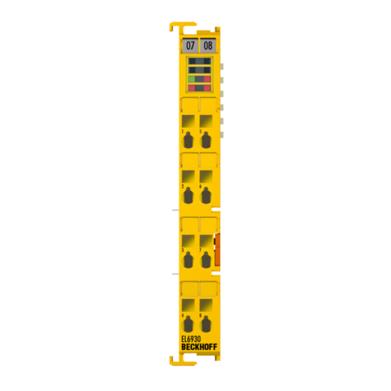
Page 31: Fig. 11 El6930 Pin Assignment
Operation 5.2.4.4 EL6930 pin assignment Fig. 11: EL6930 pin assignment Terminal point Output Signal not used, no function not used, no function not used, no function not used, no function not used, no function not used, no function not used, no function... -
Page 32: Twinsafe Reaction Times
Reaction time of the actuator. This information is typically supplied by the actuator manufacturer WDComm Watchdog time of the communication This results in the following equation for the typical reaction time: ReactionTime Sensor Input Comm Logic Comm Output Actuator with, for example ReactionTime Version: 2.0.0 EL6930... -
Page 33: Tested El1904 Devices
Safety light barriers Schmersal BNS250-11ZG Safety switch GM701S Inductive safety sensor Keyence SL-V (with PNP cable set) Safety light curtain The tests were carried out as function tests only. The information provided in the respective manufacturer documentation remains valid. EL6930 Version: 2.0.0... -
Page 34: Tested El2904 Devices
Inserting a Bus Terminal See TwinCAT automation software documentation. 5.3.4 Inserting an EL6930 An EL6930 is inserted in the same way as any other Beckhoff Bus Terminal. In the list open Safety Terminals (ELx9xx) and select the EL6930. Version: 2.0.0 EL6930... -
Page 35: Fig. 14 Inserting An El6930
Operation Fig. 14: Inserting an EL6930 Size of the process image The process image of the EL6930 is adjusted dynamically based on the TwinSAFE configuration created in the TwinCAT automation software. EL6930 Version: 2.0.0... -
Page 36: Address Settings On Twinsafe Terminals With 1023 Possible Addresses
The address 0 is not a valid TwinSAFE address! 5.3.6 Registering the TwinSAFE addresses in the TwinCAT automation software The TwinSAFE address set at the DIP switch must also be entered under the TwinSAFE Logic tab (TwinSAFE address entry). Version: 2.0.0 EL6930... -
Page 37: Creating A Twinsafe Group
A TwinSAFE group is a group of TwinSAFE terminals (inputs and outputs) that are logically linked via an EL6930. Any communication faults in the TwinSAFE connections of this group lead to the whole group being switched off. Other TwinSAFE groups are not affected. -
Page 38: Fig. 17 Creating A Twinsafe Group
Operation Fig. 17: Creating a TwinSAFE group Version: 2.0.0 EL6930... -
Page 39: Twinsafe Group Signals
At least one TwinSAFE connection of TwinSAFE group has an error FB-In FALSE All TwinSAFE connections of the TwinSAFE group have no errors Standard-Out OUT ERR TwinSAFE-Out FALSE Always FALSE, since the EL6930 has no local outputs FB-In Standard-Out EL6930 Version: 2.0.0... -
Page 40: Append A Function Block
Append Function Block in the dialog box with the left mouse button (see diagram). Fig. 19: Appending a function block The required function block can then be selected from the following window. Fig. 20: Selection of the desired function block Version: 2.0.0 EL6930... -
Page 41: Fig. 21 Appended Emergency Stop Block
Operation Fig. 21: Appended Emergency Stop block EL6930 Version: 2.0.0... -
Page 42: Fig. 22 Function Block Input Settings
Discrepancy Time can be set for monitoring the two inputs for simultaneous switching. Make Contact: Contact type setting Break Contact: Contact type setting The inputs are now activated. Fig. 23: Activated inputs The inputs can now be linked. Version: 2.0.0 EL6930... -
Page 43: Fig. 24 Link Inputs
Operation Fig. 24: Link inputs Select the variable type: Fig. 25: Select the variable type Clicking on the New button opens the following dialog: EL6930 Version: 2.0.0... -
Page 44: Fig. 26 Available Channels
The desired channel is selected and marked with the mouse. The selection is confirmed via the OK button. Fig. 27: Selection of the desired channel The name of the variables should now be entered in the Link Alias field. Version: 2.0.0 EL6930... -
Page 45: El6930 User And Version Administration
EL6930 user and version administration The EL6930 has a user administration function. The user Administrator can't be deleted, but its default password can and should be changed into a customer specific one. This is to be done via the button Change Password. -
Page 46: Fig. 30 El6930 User Administration
Operation Fig. 30: EL6930 user administration Clicking on the button Version History will bring up the version history for the EL6930 (which cannot be deleted) that indicates who activated what version of a project on the EL6930, and when. Fig. 31: Display of the version history Version: 2.0.0... -
Page 47: Loading The Project Into The El6930
The project is loaded into the EL6930 via the fieldbus. CAUTION Use only qualified tools Only use a qualified tool for loading, verifying and enabling the project on the EL6930! Click the Download button on the TwinSAFE Verifier tab for loading the project. The user must enter •... - Page 48 255 bit TwinSAFE connection Only one TwinSAFE connection between two TwinSAFE terminals is possible. Between two EL6930 logic terminals a connection can be set up that may contain up to 14 bytes safe user data. Version: 2.0.0 EL6930...
-
Page 49: Communication Between Twincat Controllers
TwinSAFE connection list and pressing the right mouse button. Fig. 34: Make known the connection created to the TwinSAFE logic terminal Create a new connection in the list of connections and create associated variables of the required type under Module1 (FSoE). EL6930 Version: 2.0.0... -
Page 50: Fig. 35 Creation Of A Variable For The Master Message
Fig. 36: Creation of a variable for the slave message These newly-created variables are now linked with the network variables already created. This is carried out for both the master and the slave message. Fig. 37: Linking the variables Version: 2.0.0 EL6930... -
Page 51: Fig. 38 Settings For The Twinsafe Connection
Fig. 38: Settings for the TwinSAFE connection If several connections are to be established, a unique ID must be set for each Publisher variable. Fig. 39: Setting a unique ID EL6930 Version: 2.0.0... -
Page 52: Creating The Profisafe Slave Connection
5.3.13 Creating the PROFIsafe slave connection The EL6930 supports a PROFIsafe slave connection, which must always be created as the first TwinSAFE connection. The procedure for this is as follows: 1. Append a TwinSAFE message structure to the TwinSAFE connection list of the first TwinSAFE Group: Version: 2.0.0... -
Page 53: Fig. 42 Select Twinsafe Group
PROFIsafe message (1 byte safe data), VARTYPE_PROFISAFEMESSAGE_6 for a 6-byte PROFIsafe message (2 bytes safe data), VARTYPE_PROFISAFEMESSAGE_8 for an 8-byte PROFIsafe message (4 bytes safe data)) on the first TxPDO under module 1 of the EL6930: Fig. 43: Select PROFIsafe variable 3. -
Page 54: Fig. 44 Link Profisafe Variable
Operation Fig. 44: Link PROFIsafe variable 4. Insert the corresponding PROFIsafe message variable on the first RxPDO under module 1 of the EL6930: Fig. 45: Insert PROFIsafe message variable 5. Link the variable with the appropriate variable of the PROFIsafe module: Version: 2.0.0... - Page 55 Operation Fig. 46: Attach variable 6. Set the connection type PROFIsafe Slave on the Connection tab of the TwinSAFE connection added in step 1: Fig. 47: Set connection type EL6930 Version: 2.0.0...
-
Page 56: Commissioning On Siemens F-Cpu
Installing the EL6930 in Step7 So that the EL6930 is selectable later in the device catalogue, the device description file for PROFIBUS (GSD) or PROFINET (GSDML) must be installed first. This can be done in the Step7 program HW Config as follows: Fig. 48: Installing the EL6930 in Step7... - Page 57 Operation Fig. 49: HW Config Overview The EL6930 presents itself to this head station as a normal module and can be added in the usual way. Fig. 50: Select EL6930 EL6930 Version: 2.0.0...
- Page 58 The F-parameters can be adjusted by double-clicking on the module. Fig. 52: F-parameters 5.4.3.1 F_Check_SeqNr Valid only for PROFIsafe version 1. With this you can set whether or not the SeqNr is included in the CRC calculation of the PROFIsafe telegram (default is No Check). Version: 2.0.0 EL6930...
- Page 59 Specification of the SIL level; the EL6930 always has SIL3. 5.4.3.3 F_CRC_Length Length of the checksum in the PROFIsafe telegram; the EL6930 has a 2-byte checksum for PROFIsafe version 1 and a 3-byte checksum for version 2. This value must be consistent with the parameter F_PAR_Version.
-
Page 60: Diagnostics
Operation Diagnostics 5.5.1 Diagnostic LEDs The LEDs Diag 1 to Diag 4 display diagnostic information for the EL6930. Fig. 53: EL6930 diagnostic LEDs 5.5.1.1 Diag 1 LED (green) The Diag 1 LED is currently always on when a project is loaded into the terminal. -
Page 61: Diagnostic Object
Temperature difference between the measuring points exceeded Supply error 0101 max. supply voltage µC1 exceeded 0102 max. supply voltage µC2 exceeded 0103 voltage fell below min. supply voltage µC1 0104 voltage fell below min. supply voltage µC2 EL6930 Version: 2.0.0... -
Page 62: Status Leds
Operation 5.5.3 Status LEDs The LEDs State 1 to State 4 indicate the current status of the EL6930. Fig. 54: EL6930 status LEDs State 1 State 2 State 3 State 4 Meaning • No project present on the terminal • Project present on the terminal •... -
Page 63: Service Life
YY: Year of manufacture Year: 2011 SW: Software version Software version: 05 HW: Hardware version Hardware version: 00 In addition the TwinSAFE terminals bear a unique serial number. 00000000 17110500 Fig. 55: Unique serial number of a TwinSAFE terminal EL6930 Version: 2.0.0... -
Page 64: Maintenance And Cleaning
Maintenance and cleaning Cleaning by the manufacturer only Do not operate the TwinSAFE component if it is impermissibly dirty according to protection class IP20. Send impermissibly dirty TwinSAFE components to the manufacturer for cleaning. TwinSAFE components are basically maintenance-free. Version: 2.0.0 EL6930... -
Page 65: Decommissioning
In accordance with the WEEE-2012/19/EU directives, you can return used devices and accessories for professional disposal. The transport costs are borne by the sender. Send the used devices with the note "For disposal" to: Beckhoff Automation GmbH & Co. KG Gebäude „Service“ Stahlstraße 31... -
Page 66: Appendix
If there is customer specific data saved on the product, it cannot be ensured that this data might not be restored through for example forensic measures, even after the data is deleted through the provided tool chain. If this data is confidential, the scrapping of the product after usage is recommended to protect this data. Version: 2.0.0 EL6930... -
Page 67: Focus Of Certificates
The current certificates of all TwinSAFE components with the underlying standards and directives can be found at https://www.beckhoff.com/en-en/support/download-finder/certificates-approvals/. If the document refers only to the first four figures of a product (ELxxxx), the certificate is valid for all available variants of the component (ELxxxx-abcd). -
Page 68: Certificate
Appendix Certificate Fig. 56: EL6930 EC Declaration of Conformity Version: 2.0.0 EL6930... - Page 69 EL6930 user administration ......................Fig. 31 Display of the version history ....................... Fig. 32 Loading the project into the EL6930 .................... Fig. 33 Link with the TwinSAFE logic terminal ..................Fig. 34 Make known the connection created to the TwinSAFE logic terminal .........
- Page 70 Fig. 45 Insert PROFIsafe message variable .................... Fig. 46 Attach variable ..........................Fig. 47 Set connection type........................Fig. 48 Installing the EL6930 in Step7 ..................... Fig. 49 HW Config Overview........................Fig. 50 Select EL6930..........................Fig. 51 HW Config............................ Fig. 52 F-parameters..........................
- Page 72 More Information: www.beckhoff.com/EL6930 Beckhoff Automation GmbH & Co. KG Hülshorstweg 20 33415 Verl Germany Phone: +49 5246 9630 info@beckhoff.com www.beckhoff.com...
Need help?
Do you have a question about the EL6930 and is the answer not in the manual?
Questions and answers