Table of Contents
Advertisement
Quick Links
Advertisement
Table of Contents

Subscribe to Our Youtube Channel
Related Manuals for Beckhoff EPP6228-0022


Summary of Contents for Beckhoff EPP6228-0022
- Page 1 Documentation | EN EPP6228-0022 IO-Link master 2022-08-25 | Version: 1.3...
-
Page 3: Table Of Contents
EPIxxxx, ERIxxxx - Setting of the IO-Link device parameters ............ 44 Access to IO-Link data ........................ 55 6.6.1 IO-Link system communication .................. 55 6.6.2 PDO Assignment...................... 56 6.6.3 Accessing IO-Link parameters .................. 57 6.6.4 Parameter data exchange.................... 58 6.6.5 ADS.......................... 59 6.6.6 Access to events ...................... 60 EPP6228-0022 Version: 1.3... - Page 4 Version identification of EtherCAT devices .................. 71 8.3.1 General notes on marking.................... 71 8.3.2 Version identification of EP/EPI/EPP/ER/ERI boxes............ 72 8.3.3 Beckhoff Identification Code (BIC) ................... 73 8.3.4 Electronic access to the BIC (eBIC)................. 75 Support and Service........................ 77 Version: 1.3 EPP6228-0022...
-
Page 5: Foreword
, XTS and XPlanar are registered trademarks of and licensed by Beckhoff Automation GmbH. Other designations used in this publication may be trademarks whose use by third parties for their own purposes could violate the rights of the owners. Patent Pending... -
Page 6: Safety Instructions
All the components are supplied in particular hardware and software configurations appropriate for the application. Modifications to hardware or software configurations other than those described in the documentation are not permitted, and nullify the liability of Beckhoff Automation GmbH & Co. KG. Personnel qualification This description is only intended for trained specialists in control, automation and drive engineering who are familiar with the applicable national standards. -
Page 7: Documentation Issue Status
YY - year of production 10 - year of production 2010 FF - firmware version 02 - firmware version 02 HH - hardware version 01 - hardware version 01 Further information on this topic: Version identification of EtherCAT devices [} 71]. EPP6228-0022 Version: 1.3... -
Page 8: Product Group: Ethercat P Box Modules
EtherCAT P Box modules are EtherCAT P slaves with degree of protection IP67. They are designed for operation in wet, dirty or dusty industrial environments. EtherCAT basics A detailed description of the EtherCAT system can be found in the EtherCAT system documentation. Version: 1.3 EPP6228-0022... -
Page 9: Product Overview
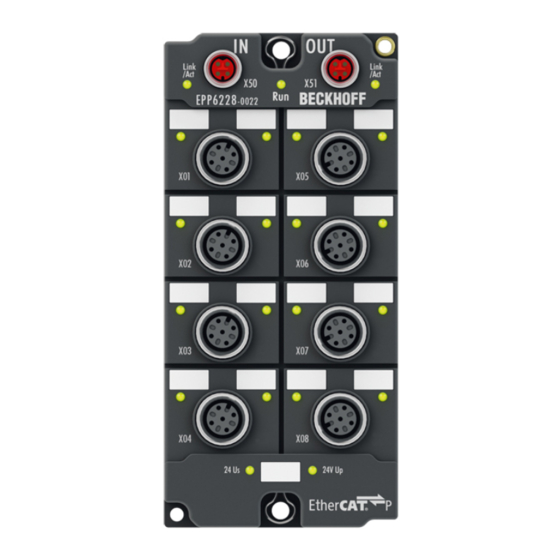
IO-Link channels, the EPP6228 features eight digital inputs on pin 2 of the respective M12 socket. In the standard setting, the IO-Link channels C/Qx of the EPP6228 accept both IO-Link devices and standard sensors with 24 V DC. Quick links Technical data [} 10] Process image [} 12] IO-Link connection [} 24] EPP6228-0022 Version: 1.3... -
Page 10: Technical Data
-40 … +85 °C Vibration resistance, shock resistance conforms to EN 60068-2-6 / EN 60068-2-27 Additional checks [} 11] EMC immunity / emission conforms to EN 61000-6-2 / EN 61000-6-4 Protection class IP65, IP66, IP67 (conforms to EN 60529) Approvals / markings Approvals / markings CE, cULus [} 26] Version: 1.3 EPP6228-0022... -
Page 11: Scope Of Supply
Scope of supply Make sure that the following components are included in the scope of delivery: • 1 x EPP6228-0022 EtherCAT P Box • 2x protective cap for EtherCAT P socket, M8, red (pre-assembled) • 10x labels, blank (1 strip of 10) Pre-assembled protective caps do not ensure IP67 protection Protective caps are pre-assembled at the factory to protect connectors during transport. -
Page 12: Process Image
Pin2 Ch7 Module 2 Module 10 Module 11 DeviceState Inputs Digital Inputs State Ch8 Pin2 Ch8 The modules "Module 3" to "Module 10" only exist in the process data if the corresponding IO-Link ports have been configured. Version: 1.3 EPP6228-0022... -
Page 13: Io-Link Basics
The IO-Link master provides the interface to the higher-level controller and controls communication with the connected IO-Link devices. The IO-Link masters from Beckhoff have several IO-Link ports, to each of which one IO-Link device can be connected. IO-Link is not a fieldbus, but rather a point-to-point connection. - Page 14 IO-Link basics CAUTION Risk of device damage The IO-Link devices must be supplied from the 24 V power supply of the IO-Link master provided for this purpose. Otherwise, damage to the IO-Link port is possible. Version: 1.3 EPP6228-0022...
-
Page 15: Establishment Of Io Link Communication
V1.0, this step is omitted and the device changes directly to OP. • Finally the cycle time is written and the device changes to OP. After that the master cyclically exchanges data with the device. EPP6228-0022 Version: 1.3... -
Page 16: Device Description Iodd
In order to be able to use the functionality of the parameter server, both the IO-Link master and the IO-Link device must be specified to V1.1. The IO-Link revision of the device can be read for the individual port under Settings [} 42]. All IO-Link masters from Beckhoff with current firmware support the IO-Link specification V1.1. -
Page 17: Mounting And Cabling
Metal parts brass, nickel-plated Contacts CuZn, gold-plated Installation position variable Protection class IP65, IP66, IP67 (conforms to EN 60529) when screwed together Dimensions (H x W x D) approx. 126 x 60 x 26.5 mm (without connectors) EPP6228-0022 Version: 1.3... -
Page 18: Fixing
Make sure that the box is grounded to low impedance via the functional earth (FE) connections. You can achieve this, for example, by mounting the box on a grounded machine bed. Fig. 2: Connection for functional earth (FE) Version: 1.3 EPP6228-0022... -
Page 19: Cabling
Mounting and cabling Cabling Tightening torques for plug connectors Screw connectors tight with a torque wrench. (e.g. ZB8801 from Beckhoff) Connector diameter Tightening torque 0.4 Nm 0.6 Nm EPP6228-0022 Version: 1.3... -
Page 20: Ethercat P
EtherCAT P Box to the next EtherCAT P Box in a simple manner. NOTE Note the maximum current. Ensure that the maximum permitted current of 3 A for the M8 connectors is not exceeded when redirecting EtherCAT P. Version: 1.3 EPP6228-0022... - Page 21 Core color Tx + yellow Rx + white Rx - : peripheral voltage, +24 V blue Tx - : control voltage, +24 V orange Housing Shield Shield Shield The core colors apply to EtherCAT P cables and ECP cables from Beckhoff. EPP6228-0022 Version: 1.3...
- Page 22 Each EtherCAT slave has a green LED labelled "Run". The LED signals the status of the slave in the EtherCAT network: Meaning Slave is in "Init" state flashes uniformly Slave is in "Pre-Operational“ state flashes sporadically Slave is in "Safe-Operational" state Slave is in "Operational" state Description of the EtherCAT slave states Version: 1.3 EPP6228-0022...
- Page 23 Further information can be found in the quick start guide IO configuration in TwinCAT in chapter "Configuration of EtherCAT P with TwinCAT". Voltage drop on the supply line I = 3 A 0.14 mm² 0.22 mm² Vert. Faktor: 0,22 cm / V 0.34 mm² Cable length (m) EPP6228-0022 Version: 1.3...
-
Page 24: Io-Link
Fig. 7: M12 socket Contact Function Description Core color Supply voltage (U brown Digital input white blue IO-Link data cable black grey The core colors apply to M12 sensor cables from Beckhoff: • ZK2000-5xxx • ZK2000-6xxx • ZK2000-7xxx. Version: 1.3 EPP6228-0022... - Page 25 IO-Link communication active green illuminated Logic level high Port configured as digital input or output 2 - Digital input DI The LED lights up when a high level is present on the digital input DI. EPP6228-0022 Version: 1.3...
-
Page 26: Ul Requirements
To meet the UL requirements, EtherCAT Box Modules has to be operated only at an ambient temperature range of -25 °C to +55 °C! Marking for UL All EtherCAT Box Modules certified by UL (Underwriters Laboratories) are marked with the following label. Fig. 9: UL label Version: 1.3 EPP6228-0022... -
Page 27: Disposal
Products marked with a crossed-out wheeled bin shall not be discarded with the normal waste stream. The device is considered as waste electrical and electronic equipment. The national regulations for the disposal of waste electrical and electronic equipment must be observed. EPP6228-0022 Version: 1.3... -
Page 28: Commissioning And Configuration
Commissioning and configuration Commissioning and configuration Integrating into a TwinCAT project The procedure for integration in a TwinCAT project is described in these Quick start guide. Version: 1.3 EPP6228-0022... -
Page 29: Configuration Of The Io Link Master
EtherCAT XML device description and configuration files The display matches that of the CoE objects from the EtherCAT XML Device Description. We rec- ommend downloading the latest XML file from the download area of the Beckhoff website and in- stalling it according to installation instructions. -
Page 30: Configuration Of The Io-Link Devices
The device catalog contains an alphabetically sorted list of the IO-Link devices for which a device description (IODD) exists in the local TwinCAT installation. The IODDs for the EPIxxxx, ERIxxxx IO-Link Box modules from Beckhoff can be downloaded via the Download finder. The downloaded zip file contains the IODD device description files for the Beckhoff EPIxxxx, ERIxxxx IO-Link Box modules. -
Page 31: Integrating Io-Link Devices
• Manual integration of the IO-Link devices via “Create Device” should only be carried out if the IODD of the vendor and the IO-Link device are not available at the time of project creation. Fig. 12: Creating IO-Link devices EPP6228-0022 Version: 1.3... - Page 32 2. Searching for the desired IO-Link sensor/device by entering them in the search mask; see the figure below (1) 3. Selecting the desired IO-Link sensor/device. Move the mouse pointer over the figure of the desired IO- Link sensor/device. A blue download icon appears, see the following figure (2). Version: 1.3 EPP6228-0022...
- Page 33 (3)) that the .xml file already exists. Fig. 15: IODD Finder, display of an already imported device description ð The imported device descriptions are listed in a tree structure in the “Catalog” field of the IO-Link tab, sorted by vendor. EPP6228-0022 Version: 1.3...
- Page 34 Example of port assignment on the IO link master EL6224 Port1: Port2: Port3: EPI3174-0002 is assigned is configured as digital input EPI1008-0001 will be assigned Process data of Port1 and Port2 are displayed in the Solution Explorer. Version: 1.3 EPP6228-0022...
- Page 35 ð The information window lists the connected device for each of the four ports. Only port2 of the master is assigned an IO-Link device. ð Confirm with the OK button. Fig. 17: Information “Scan devices” 2. To be able to work with the devices, the button “Reload Devices” must be clicked. EPP6228-0022 Version: 1.3...
- Page 36 The IO-Link devices are now entered in the General display. The Port2 “Details” field displays information about the connected device. Additionally the tabs Settings [} 37] and Parameter [} 38] can be opened. Fig. 18: Device at Port2, Display “Details”, open tabs “Settings” and “Parameter” Version: 1.3 EPP6228-0022...
- Page 37 Show settings of the device 3. Right-click on port2, to display more details in dialog “Settings”. 4. If necessary, change the settings as described in chapter Settings of the IO-Link devices [} 42]. Fig. 19: Settings of the device assigned to port2 EPP6228-0022 Version: 1.3...
- Page 38 ð The Parameters of of the respective IO link device are listed. 6. Parameterize the device as described in chapter EPIxxxx, ERIxxxx - Setting of the IO-Link device parameters [} 44]. Fig. 20: Parameter of the device assigned to port2 Version: 1.3 EPP6228-0022...
- Page 39 Even when manually creating and scanning, the IODD should always be read in as well in order to display further sensor-specific information. 7. In the “Settings” tab of the IO link devices further settings can be made as described in chapter Settings of the IO-Link devices [} 42]. EPP6228-0022 Version: 1.3...
-
Page 40: Removal Of Io-Link Devices
2. Activate the IO link configuration [} 41], so that changes become effective. ð The already create process data are removed. Fig. 23: The device was removed from the port2, the process data no longer displayed in the tree. Version: 1.3 EPP6228-0022... -
Page 41: Activating The Configuration
Changes in the IO-Link configuration tool only become effective when you activate the IO-Link configuration. There are two ways to activate the IO-Link configuration: • Click on the "Reload Devices" button • Activate the TwinCAT configuration: Click on the "Activate Configuration" button EPP6228-0022 Version: 1.3... -
Page 42: Settings Of The Io-Link Devices
1. right-click on the port to open the context menu and select “Settings”. ð A new tab “Portx:: Settings” opens where the settings described below can be made. Fig. 24: Context menu - Settings Fig. 25: Settings of the IO-Link devices Version: 1.3 EPP6228-0022... - Page 43 ð complex data types (process data) are created as octet strings. Advantage: simple further processing in the 9. Firmware Update of the Beckhoff IO-Link devices For a firmware update use the “Download” button. Observe the description in the documentation of EPIxxxx boxes in chapter Firmware Update des IO-Link Devices.
-
Page 44: Epixxxx, Erixxxx - Setting Of The Io-Link Device Parameters
Restarting the IO link device or restoring of the application parameters is possible via the parameter Standard Command [} 53]. Application specific information can be specified in parameter (0x0018) Application Specific Tag [} 54]. Version: 1.3 EPP6228-0022... - Page 45 Deviations are indicated by a pen-symbol in front of the index. If there are different values in the “Value” field, the value “Compare” is displayed (see Index 0x0018 “Application Specific Tag”). Fig. 27: Display of deviating data in the “Parameter” tab EPP6228-0022 Version: 1.3...
- Page 46 Commissioning and configuration Fig. 28: Compare configuration and sensor data Version: 1.3 EPP6228-0022...
- Page 47 ð The data is written to the device (offline configuration is possible). The successful writing process is confirmed via a storing symbol in front of the index. Fig. 29: Write parameter data to the sensor, read parameter data from the sensor. EPP6228-0022 Version: 1.3...
- Page 48 1. Press the “Set Default” button. ð All parameter values are set to the default settings. Write default-values to the sensor Note that the default-values must also be written to the device via the “Write” button. Fig. 30: Reset parameter values to default Version: 1.3 EPP6228-0022...
- Page 49 5. Write the new parameter values to the sensor via “Write” button. ð The data is written to the device (offline configuration is possible). The successful writing process is confirmed via a storing symbol in front of the index. Fig. 31: Parameterization IO-Link device - Export / Import EPP6228-0022 Version: 1.3...
- Page 50 Commissioning and configuration “Store” button 1. Click “Store” (data storage): ð The Beckhoff IO-Link master stores sensor-dependent-data, e. g. the following parameters (0x0018) “Application-Specific Tag”, (0x08n0) “Settings” and 0x3800 “Range Settings”. The success of storing process is marked with the storing symbol.
- Page 51 Use an ADS Write function block for activating the store-function via the plc. The following figure shows a sample code for activation of the store-Button (command 0x05 “ParamDownloadStore”) Fig. 34: Sample code for activation of the store-function via the plc EPP6228-0022 Version: 1.3...
- Page 52 Commissioning and configuration Fig. 35: Store parameters Version: 1.3 EPP6228-0022...
- Page 53 3. Use the “Write” button (as described above [} 47]). ð The data is written to the device (offline configuration is possible). The successful writing process is confirmed via a storing symbol in front of the index. Fig. 36: Parameters IO-Link device “Standard Command” EPP6228-0022 Version: 1.3...
- Page 54 1. Click “Application-Specific Tag” in the parameter list, then double-click “Application-Specific Tag” in the right-hand field. 2. Enter application-specific information and confirm with the Enter key. 3. Use the Write [} 47] button and the Store [} 50] button, if required (as described above). Fig. 37: Parameters IO-Link device: “Application Specific Tag” Version: 1.3 EPP6228-0022...
-
Page 55: Access To Io-Link Data
In principle cyclic and acyclic data are exchanged. The cyclic process data can be accessed via the PDOs, the acyclic data via AoE [} 57]. The events are additionally displayed under Diag History [} 60] in the System Manager. • Cyclic data: - Process data - Value status • Acyclic data: - Device data - Events EPP6228-0022 Version: 1.3... -
Page 56: Pdo Assignment
If data types are used that don't conform to IEC61131-3, they are represented as octed strings. The state of the IO-Link ports 1 to 4 is displayed via index 0xF100:0n. The indices 0xF101:xx provide general diagnosis data. Version: 1.3 EPP6228-0022... -
Page 57: Accessing Io-Link Parameters
0xB_ = error PreOP/Data storage (error in IO-Link State PreOP) 6.6.3 Accessing IO-Link parameters The exchange of the acyclic data takes place via a specified index and subindex range that is device-specific and can be read about in the corresponding vendor documentation. EPP6228-0022 Version: 1.3... -
Page 58: Parameter Data Exchange
• INITMASTER: Readout the IO-Link device and check the communication parameters • INITDEVICE: Initialization of the IO-Link device • PREOPERATE: Parameter server is running • OPERATE: The port is used for IO-Link communication • STOP: Communication is stopped (COM-stop) Version: 1.3 EPP6228-0022... -
Page 59: Ads
The IO link addressing with index and subindex is coded in the Indexoffset. The Indexoffset has a size of 4 bytes and is subdivided as follows: 2-byte index, 1-byte reserve, 1-byte subindex. • Example: Indexoffset 0x12340056 corresponds to index 0x1234 and subindex 56 EPP6228-0022 Version: 1.3... -
Page 60: Access To Events
0. • Export Diag History: the events that have occurred can be exported as a "txt" file and thus archived. • Advanced: this field currently (as at 3 quarter 2015) has no function. Version: 1.3 EPP6228-0022... -
Page 61: Restoring The Delivery State
Fig. 43: Entering a restore value in the Set Value dialog Alternative restore value In some older terminals / boxes the backup objects can be switched with an alternative restore value: Decimal value: 1819238756 Hexadecimal value: 0x6C6F6164 An incorrect entry for the restore value has no effect. EPP6228-0022 Version: 1.3... -
Page 62: Decommissioning
Commissioning and configuration Decommissioning WARNING Risk of electric shock! Bring the bus system into a safe, de-energized state before starting disassembly of the devices! Version: 1.3 EPP6228-0022... -
Page 63: Diagnosis
0x7_ invalid Cycle Time 0x8_ invalid PD in length 0x9_ invalid PD out length 0xA_ no Device detected 0xB_ error PreOP/Data storage Combinations are possible and are output as an addition of the values (see note below). EPP6228-0022 Version: 1.3... - Page 64 If diagnosis messages occur simultaneously, the value is output as a sum in the status byte of the relevant channel. • Often 0x03 "Port in communication OP" and 0x08 "Process Data Invalid Bit" occur simultane- ously: 0x03 + 0x08 = 0x0B (11 ð The value 0x0B (11 ) is output in the status byte. Version: 1.3 EPP6228-0022...
-
Page 65: Ads Error Codes
Error codes are generated in the event of an error during ADS access to an IO-Link device. The possible error codes are listed in tables C.1 and C.2. Example of an AdsReturnCode AdsReturnCode 0x80110700 - 80: Device Application Error (IO-Link Spec), - 11: Index not Available (IO-Link Spec), - 0700: General ADS Error EPP6228-0022 Version: 1.3... - Page 66 Vendor specific 0x81 0x00 UNSPECIFIC This ErrorType will be propagated directly to higher level processing elements as an error (no warning) by the Vendor specific 0x81 0x01 to VENDOR_SPECIFIC Master. 0xFF Table C.1 ErrorTypes, IO-Link Spec Version: 1.3 EPP6228-0022...
- Page 67 (see parameter length overrun) 0x5200) Events from legacy Devices shall be redirected in com- patibility mode to this derived ErrorType Table C.2 Derived ErrorTypes, IO-Link Spec EPP6228-0022 Version: 1.3...
-
Page 68: Further Error Diagnosis
In case of error these objects can be used to compare the configuration with the actual state. Lost Frame Counter The Lost Frame counter in object 0xA0n0:02 is for the diagnosis of the transmission quality. TwinCAT provides the possibility here to diagnose problems, e. g. with the wiring, EMC or power supply. Version: 1.3 EPP6228-0022... -
Page 69: Appendix
(ph-Value > 12) > 40°C: not resistant Acetic acid not resistant Argon (technical clean) resistant • resistant: Lifetime several months • non inherently resistant: Lifetime several weeks • not resistant: Lifetime several hours resp. early decomposition EPP6228-0022 Version: 1.3... -
Page 70: Accessories
Torque cable key for M12 / wrench size 13 for ZB8801-0000 ZB8801-0003 Torque cable key for M12 field assembly / wrench size 18 for ZB8801-0000 Further accessories Further accessories can be found in the price list for fieldbus components from Beckhoff and online at https://www.beckhoff.com. Version: 1.3 EPP6228-0022... -
Page 71: Version Identification Of Ethercat Devices
Associated and synonymous with each revision there is usually a description (ESI, EtherCAT Slave Information) in the form of an XML file, which is available for download from the Beckhoff web site. From 2014/01 the revision is shown on the outside of the IP20 terminals, see Fig. “EL5021 EL terminal, standard IP20 IO device with batch number and revision ID (since 2014/01)”. -
Page 72: Version Identification Of Ep/Epi/Epp/Er/Eri Boxes
Version identification of EP/EPI/EPP/ER/ERI boxes The serial number/ data code for Beckhoff IO devices is usually the 8-digit number printed on the device or on a sticker. The serial number indicates the configuration in delivery state and therefore refers to a whole production batch, without distinguishing the individual modules of a batch. -
Page 73: Beckhoff Identification Code (Bic)
8.3.3 Beckhoff Identification Code (BIC) The Beckhoff Identification Code (BIC) is increasingly being applied to Beckhoff products to uniquely identify the product. The BIC is represented as a Data Matrix Code (DMC, code scheme ECC200), the content is based on the ANSI standard MH10.8.2-2016. - Page 74 Fig. 46: Example DMC 1P072222SBTNk4p562d71KEL1809 Q1 51S678294 An important component of the BIC is the Beckhoff Traceability Number (BTN, position 2). The BTN is a unique serial number consisting of eight characters that will replace all other serial number systems at Beckhoff in the long term (e.g.
-
Page 75: Electronic Access To The Bic (Ebic)
Electronic access to the BIC (eBIC) Electronic BIC (eBIC) The Beckhoff Identification Code (BIC) is applied to the outside of Beckhoff products in a visible place. If possible, it should also be electronically readable. Decisive for the electronic readout is the interface via which the product can be electronically addressed. - Page 76 EtherCAT, the eBIC of the top-level device is located in the CoE object directory 0x10E2:01 and the eBICs of the sub-devices follow in 0x10E2:nn. Profibus/Profinet/DeviceNet… Devices Currently, no electronic storage and readout is planned for these devices. Version: 1.3 EPP6228-0022...
-
Page 77: Support And Service
Please contact your Beckhoff branch office or representative for local support and service on Beckhoff products! The addresses of Beckhoff's branch offices and representatives round the world can be found on her internet pages: https://www.beckhoff.com You will also find further documentation for Beckhoff components there. - Page 79 More Information: www.beckhoff.com/epp6228-0022 Beckhoff Automation GmbH & Co. KG Hülshorstweg 20 33415 Verl Germany Phone: +49 5246 9630 info@beckhoff.com www.beckhoff.com...
Need help?
Do you have a question about the EPP6228-0022 and is the answer not in the manual?
Questions and answers