Table of Contents
Advertisement
Quick Links
Advertisement
Table of Contents

Related Manuals for Emerson Rosemount 370XA


Summary of Contents for Emerson Rosemount 370XA
- Page 1 Revision A 7P00370-H01 April 2014 370XA Gas Chromatograph System Reference Manual...
- Page 2 PRODUCT. RESPONSIBILITY FOR PROPER SELECTION, USE AND MAINTENANCE OF ANY SELLER PRODUCT REMAINS SOLELY WITH THE PURCHASER AND END-USER. ROSEMOUNT AND THE ROSEMOUNT ANALYTICAL LOGO ARE REGISTERED TRADEMARKS OF ROSEMOUNT ANALYTICAL. THE EMERSON LOGO IS A TRADEMARK AND SERVICE MARK OF EMERSON ELECTRIC CO. ©2014 ROSEMOUNT ANALYTICAL, INC.
- Page 3 WARRANTY 1. LIMITED WARRANTY: Subject to the limitations contained in Section 2 herein and except as otherwise expressly provided herein, Rosemount Analytical (“Seller”) warrants that the firmware will execute the programming instructions provided by Seller, and that the Goods manufactured or Services provided by Seller will be free from defects in materials or workmanship under normal use and care until the expiration of the applicable warranty period.
-
Page 4: Table Of Contents
TA B L E O F C O N T E N T S Section 1 Introducing the 370XA ......1-1 General description . - Page 5 System Reference Manual 370XA Gas Chromatograph 7P00370-H01 APRIL 2014 Actuation gas ..........3-25 Helium actuation gas .
- Page 6 370XA Gas Chromatograph System Reference Manual APRIL 2014 7P00370-H01 View a live chromatogram ......4-6 View an archived chromatogram .
- Page 7 System Reference Manual 370XA Gas Chromatograph 7P00370-H01 APRIL 2014 Advanced configuration and operation topics ..... 4-32 Validation ......... . . 4-32 Prepare for a validation .
-
Page 8: Section 1 Introducing The 370Xa
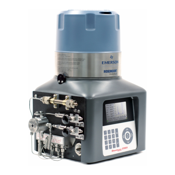
General description The 370XA gas chromatograph from Rosemount Analytical is the latest analyzer to join the XA series of Emerson gas chromatographs. Designed to simplify natural gas measurement analysis, the 370XA provides greater ease of use and increased measurement performance for your C6+ BTU/CV analysis. - Page 9 System Reference Manual 370XA Gas Chromatograph 7P00370-H01 APRIL 2014 Structurally, the 370XA has two major sections. The upper section (1) consists of the analysis module (3). The lower section (2) of the gas chromatograph houses the electronics (4) and the LCD display. 1 - 2...
-
Page 10: Specifications
370XA Gas Chromatograph System Reference Manual APRIL 2014 7P00370-H01 Specifications Electronics Power 24V DC (standard) at the unit. 21-30V DC (operating range) at the unit. Class 2 power supply as required for CSA approval. Note: Provide the GC with one 5-amp circuit breaker for protection. - Page 11 System Reference Manual 370XA Gas Chromatograph 7P00370-H01 APRIL 2014 Performance Application four-minute C6+ analysis Repeatability Controlled environment +/-0.0125% calorific value +/- 0.125 BTU/scf per 1000 BTU/scf -20 °C (-4 °F) to 60 °C (140 °F) +/-0.025% calorific value +/- 0.25 BTU/scf per 1000 BTU/scf Metrology approvals Measurement Canada, NMi (OIML) Calculations...
- Page 12 370XA Gas Chromatograph System Reference Manual APRIL 2014 7P00370-H01 Standard communications Ethernet Two available connections: one RJ-45 plug-in port and one 4-wire termination. Both with 10/100 Mbps. Analog input One standard input filtered with transient protection, 4–20 mA that is user scalable and assignable.
-
Page 13: Certifications
System Reference Manual 370XA Gas Chromatograph 7P00370-H01 APRIL 2014 Certifications ATEX Manufacturer Rosemount Analytical, Inc. Houston, TX, USA Product Danalyzer 370XA Gas Chromatograph Certificate number Sira 13ATEX1030 Certification code Ex d IIB+H2 T6 Gb Ambient range Ta = -20 °C to +60 °C Serial number device dependent Year of manufacture... - Page 14 370XA Gas Chromatograph System Reference Manual APRIL 2014 7P00370-H01 Class I, Div. 1; Groups B, C, D; T6; Type 4X Class I, Zone 1; Ex/AEx d IIB + H ; T6; IP65 1 - 7...
- Page 15 System Reference Manual 370XA Gas Chromatograph 7P00370-H01 APRIL 2014 This page is intentionally left blank. 1 - 8...
-
Page 16: Section 2 Anatomy Of The 370Xa
Section 2: Anatomy of the 370XA Exterior: Front View Explosion-proof dome Unscrew the explosion-proof dome to gain access to the analytical oven. Explosion-proof body The explosion-proof body houses the electronics. Local operator interface The local operator interface (LOI) contains keys and an LCD display for interacting with the gas chromatograph. -
Page 17: Exterior: Left View
System Reference Manual 370XA Gas Chromatograph 7P00370-H01 APRIL 2014 Exterior: Left View Locking bolt Secures the dome to the enclosure. To engage the lock, screw in the hex screw with a 2 mm hex wrench; to release the lock, unscrew the hex screw with a 2mm hex wrench. Cable entry M32 conduit entry. -
Page 18: Exterior: Right View
370XA Gas Chromatograph System Reference Manual APRIL 2014 7P00370-H01 Grounding lug Connects to an external grounding system, as required for ATEX-certified installations. Tubing bulkhead The central hub for the sample, carrier, and other gas inlets. Exterior: Right View Upper cable entry Certification type Additionally supplied certified parts M32-to-¾-inch adapter and a ¾-inch sealing plug... - Page 19 System Reference Manual 370XA Gas Chromatograph 7P00370-H01 APRIL 2014 Port hole Unscrew and remove to gain access to the field wiring connections and the circuit boards. Lower cable entry Supplied with an M32 certified plug and an M32-to-¾ NPT adapter. This is the most convenient entry point for connecting cables to the Ethernet port, communications ports, and external device terminals.
-
Page 20: Exterior: Rear View
370XA Gas Chromatograph System Reference Manual APRIL 2014 7P00370-H01 Exterior: Rear View Mounting bolts These M8 bolts are used to mount the GC to its final destination, depending upon the mounting configuration chosen. Each bolt is 1.8 centimeters long. 2 - 5... -
Page 21: Exterior: Local Operator Interface
System Reference Manual 370XA Gas Chromatograph 7P00370-H01 APRIL 2014 Exterior: Local Operator Interface LCD display Has a display resolution of 480x272 (WQVGA) and it supports ASCII text and graphics modes. Back lighting and brightness can be adjusted for different ambient conditions. Arrow keys Select/Edit key The function of this key depends on context. - Page 22 370XA Gas Chromatograph System Reference Manual APRIL 2014 7P00370-H01 Alphanumeric keys To enter a letter into an alphanumeric field, press the appropriate key to cycle through its alphanumeric options until the desired letter appears. For example, to enter an “H”, you must press the 4GHI key three times.
-
Page 23: Interior: Back Plane
System Reference Manual 370XA Gas Chromatograph 7P00370-H01 APRIL 2014 Interior: Back plane TB1. Digital input TB3. Digital output TB5. Wired Ethernet TB9. COM2 port RJ-45. Plug-in Ethernet port CPU. CPU board TB2. Analog input TB4. COM1 port TB8. Power TB10. Analog outputs (2) J8. -
Page 24: Interior: Maintainable Module
370XA Gas Chromatograph System Reference Manual APRIL 2014 7P00370-H01 Interior: Maintainable Module 2 - 9... - Page 25 System Reference Manual 370XA Gas Chromatograph 7P00370-H01 APRIL 2014 Heater cap Controls the thermal environment surrounding the analytical components of the module, which is crucial to ensure the reliable and repeatable analysis. Chromatography columns Separates the sample gas into its component compounds so that they can be detected and measured.
- Page 26 370XA Gas Chromatograph System Reference Manual APRIL 2014 7P00370-H01 Sample shut-off valve Shuts off the flow of gases to the sample loop for the first five seconds of an analysis to allow the sample loop to equalize to atmospheric pressure through the sample vent. This ensures that a consistent amount of sample gas is injected into the analytical columns each analysis cycle regardless of the sample pressure or flow.
- Page 27 System Reference Manual 370XA Gas Chromatograph 7P00370-H01 APRIL 2014 Valve actuation solenoids Each analytical valve is actuated by its own four-way solenoid. The actuation solenoid directs the actuation gas to the appropriate pistons in its associated actuation valve. Carrier gas pressure control valve Electronically controls the carrier gas pressure.
-
Page 28: Section 3 Installing The 370Xa
Section 3: Installing the 370XA Site Requirements 3.1.1 Site requirements Consider the following when choosing an installation site for the GC: • This gas chromatograph is designed to operate at temperatures between -20 ºC (-4 ºF) and 60 ºC (140 ºF). •... -
Page 29: Inspection And Verification Of Received Equipment
System Reference Manual 370XA Gas Chromatograph 7P00370-H01 APRIL 2014 3.2.2 Inspection and verification of received equipment Check the equipment against the packing slip to see if the shipment is complete. Inspect the equipment for damage incurred during shipment. If any parts or assemblies appear to have been damaged, do the following: File a claim with the carrier. -
Page 30: Minimum Installation Clearances
370XA Gas Chromatograph System Reference Manual APRIL 2014 7P00370-H01 3.3.1 Minimum installation clearances 3.3.2 Pole mount The pole mount arrangement uses a pair of U-shaped pipe clamps and a mounting bracket to attach the gas chromatograph to a pole that is four inches in diameter. An optional floor mount is available that is a pole welded to a square base with mounting holes. -
Page 31: Parts
System Reference Manual 370XA Gas Chromatograph 7P00370-H01 APRIL 2014 3.3.2.1 Parts Mounting bracket 4-inch pipe clamps, each with two nuts Optional 4-inch diameter pole with metal base containing mounting holes suitable for ½-inch anchors 3 - 4... -
Page 32: Dimensions
370XA Gas Chromatograph System Reference Manual APRIL 2014 7P00370-H01 3.3.2.2 Dimensions 3 - 5... -
Page 33: Optional Gas Bottle Accessories
System Reference Manual 370XA Gas Chromatograph 7P00370-H01 APRIL 2014 3.3.2.3 Optional gas bottle accessories Carrier gas bottle cradle assemblies (2) Calibration gas bottle cradle assembly 3 - 6... -
Page 34: Instructions
370XA Gas Chromatograph System Reference Manual APRIL 2014 7P00370-H01 3.3.2.4 Instructions Slide the u-bolt plastic inserts (1) onto the pole and place the lower clamp approximately 1 m (40 inches) from the ground and the upper clamp 27 cm (10¾ inches) above the lower clamp. - Page 35 System Reference Manual 370XA Gas Chromatograph 7P00370-H01 APRIL 2014 Slide the two u-bolts (1) into the plastic inserts. 3 - 8...
- Page 36 370XA Gas Chromatograph System Reference Manual APRIL 2014 7P00370-H01 Attach the mounting frame to the pole by matching the frame’s mounting holes to the prongs of the pipe clamps. Tighten the nuts onto the prongs. The mounting bracket should be firmly attached to the pole. “Secure the 370XA to the mounting bracket”...
-
Page 37: Wall Mount
System Reference Manual 370XA Gas Chromatograph 7P00370-H01 APRIL 2014 3.3.3 Wall mount 3.3.3.1 Parts Mounting bracket Four 7/16” (10mm) mounting bolts with washers NOTICE ⅜ You will also need four 10mm ( -in) threaded wall anchors that are capable of supporting at least 50 pounds (22 kg). -
Page 38: Dimensions
370XA Gas Chromatograph System Reference Manual APRIL 2014 7P00370-H01 3.3.3.2 Dimensions 3 - 11... -
Page 39: Instructions
System Reference Manual 370XA Gas Chromatograph 7P00370-H01 APRIL 2014 3.3.3.3 Instructions The wall must be able to hold approximately 50 pounds (22 kg). Install four threaded wall anchors according to the dimensions given in the graphic below. 3 - 12... - Page 40 370XA Gas Chromatograph System Reference Manual APRIL 2014 7P00370-H01 Mount the wall mounting frame to the wall and tighten the mounting nuts. “Secure the 370XA to the mounting bracket” on page 3-14. 3 - 13...
-
Page 41: Secure The 370Xa To The Mounting Bracket
System Reference Manual 370XA Gas Chromatograph 7P00370-H01 APRIL 2014 3.3.4 Secure the 370XA to the mounting bracket Screw two bolts into the top mounting holes of the GC without the washers, leaving ½ inch (15 mm) of the thread exposed. 3 - 14... - Page 42 370XA Gas Chromatograph System Reference Manual APRIL 2014 7P00370-H01 Maneuver the GC to insert the two top bolts into the eyelets of the mounting bracket and allow the bolts to drop down and hold the GC loosely on the bracket. Screw in the two bottom bolts through the mounting bracket with the washers on.
-
Page 43: Mount The Sample Conditioning System
System Reference Manual 370XA Gas Chromatograph 7P00370-H01 APRIL 2014 Mount the sample conditioning system There are several sample conditioning systems (SCS) that are available for the 370XA. The side-mounted single stream SCS includes all of the components required for single stream natural gas applications on a metal plate that conveniently attaches to the side of the 370XA. -
Page 44: Attach The Single-Stream, Side-Mounted Sample Conditioning System To The Gc
370XA Gas Chromatograph System Reference Manual APRIL 2014 7P00370-H01 3.4.1 Attach the single-stream, side-mounted sample conditioning system to the GC Use the two one-inch bolts and a 5/32 hex wrench to screw the large mounting bar tightly to the left side of the plate with the angled foot facing the edge of the plate. - Page 45 System Reference Manual 370XA Gas Chromatograph 7P00370-H01 APRIL 2014 Use the two half-inch bolts and a 5/32 hex wrench to screw the small mounting bar loosely to the right side of the plate with the angled foot facing the edge of the plate. 3 - 18...
- Page 46 370XA Gas Chromatograph System Reference Manual APRIL 2014 7P00370-H01 Angle the plate onto the left side of the GC so that the large mounting block fits behind the left edge of the cut-out. Swing the right side of the plate around until it attaches to the right side of the cut-out.
- Page 47 System Reference Manual 370XA Gas Chromatograph 7P00370-H01 APRIL 2014 Slide the small mounting bar (1) to the right so that it fits behind the right edge of the cut-out. Tighten the small mounting block's screws. 3 - 20...
-
Page 48: Connect Sample Conditioning System Tubing To The Gc
370XA Gas Chromatograph System Reference Manual APRIL 2014 7P00370-H01 3.4.2 Connect sample conditioning system tubing to the Use the tubing supplied with the sample system to connect the stream, calibration, actuation, and calibration gases from the sample plate to the GC’s manifold block. (1) Calibration tubing (2) Sample tubing (3) Actuation tubing... - Page 49 System Reference Manual 370XA Gas Chromatograph 7P00370-H01 APRIL 2014 The atmospheric vents should be connected to a vent line of at ⅜ least -inch diameter that is routed to the atmosphere in a safe area to ensure there is no back-pressure created on the vents..
-
Page 50: Connect To The Carrier Gas
370XA Gas Chromatograph System Reference Manual APRIL 2014 7P00370-H01 Connect to the carrier gas Carrier gas specifications Carrier gas Hydrogen or helium Purity 99.9995% (ultra high) Moisture content Less than 5 ppm Hydrocarbon content Less than 0.5ppm Supply pressure 90 PSI (620 kPaG) Carrier gas flow Approx. - Page 51 System Reference Manual 370XA Gas Chromatograph 7P00370-H01 APRIL 2014 The following image shows the carrier gas connector (1). The carrier gas must be regulated from bottle pressure to 90 PSI (620 kPa) using a two-stage bottle regulator with stainless steel diaphragms.
-
Page 52: Actuation Gas
370XA Gas Chromatograph System Reference Manual APRIL 2014 7P00370-H01 Actuation gas The analytical valves require actuation gas to operate. When helium is used as a carrier gas, the default configuration is to also use helium as the actuation gas. When hydrogen is used as a carrier gas, or if there is a desire to minimize helium usage, another clean dry gas such as nitrogen or clean-dry air should be used as the actuation gas. -
Page 53: Connect To The Calibration Gas
System Reference Manual 370XA Gas Chromatograph 7P00370-H01 APRIL 2014 Connect to the calibration gas The gas chromatograph requires a high quality, certified calibration gas to ensure accurate analysis. Although the 370XA is typically set for an automatic daily calibration run in custody transfer applications, it can be configured with MON2020 for any time frequency, or set to manual calibration only. - Page 54 370XA Gas Chromatograph System Reference Manual APRIL 2014 7P00370-H01 2,2 Dimethyl butane is the lightest C6+ component and should be added to the n-Hexane concentration to be entered as the C6+ calibration concentration. The following image shows the calibration gas connector (1). Regulate the calibration gas from bottle pressure to 15 PSI (100 kPa) using a two-stage bottle regulator with stainless steel diaphragms.
-
Page 55: Connect To The Sample Gas
System Reference Manual 370XA Gas Chromatograph 7P00370-H01 APRIL 2014 Connect to the sample gas The sample handling system controls how the gas sample is extracted, conditioned, and transported to the analyzer and is critical to the accurate and reliable performance of any gas chromatograph. The basic principles of sample handling are as follows: •... - Page 56 370XA Gas Chromatograph System Reference Manual APRIL 2014 7P00370-H01 The following image shows the sample gas connector (1). The sample pressure entering the gas chromatograph sample conditioning system should be between 15 and 30 PSI (100 and 200 kPa). If the pressure in the pipeline is higher than this, regulate the sample pressure to this pressure with a dual stage regulator.
- Page 57 System Reference Manual 370XA Gas Chromatograph 7P00370-H01 APRIL 2014 To avoid this hydrocarbon condensation, heat the regulator and sample lines to the gas chromatograph to at least 30 °F (17 °C) above the expected temperature of the flowing gas stream. Use stainless steel tubing and fittings for all of the sample lines.
-
Page 58: Electrical Connections
370XA Gas Chromatograph System Reference Manual APRIL 2014 7P00370-H01 NOTICE Install the probe/regulator first, immediately followed by the coalescing filter and then the membrane filter. See Appendix B for a recommended natural gas installation. • Pressure Regulators and Flow Controllers Use stainless steel wetted materials. - Page 59 System Reference Manual 370XA Gas Chromatograph 7P00370-H01 APRIL 2014 your gas chromatograph is ATEX/IECeX-certified then M32-certified plugs will be shipped with your GC. The maximum wire size for all of the 370XA’s terminals is 12 AWG or 3.5 mm . The terminals can be unplugged from the back plane to make the connection, and then plugged back into place.
-
Page 60: Terminal Wiring Diagram
370XA Gas Chromatograph System Reference Manual APRIL 2014 7P00370-H01 3.9.1 Terminal wiring diagram 3 - 33... -
Page 61: Connect To Serial Ports
System Reference Manual 370XA Gas Chromatograph 7P00370-H01 APRIL 2014 3.10 Connect to serial ports The 370XA has two serial ports on the back plane that can be individually configured for RS-232 or RS-485 mode using the local operator interface or MON2020. The cables for the serial communications should be individually shielded pairs with the shield connected to a clean electrical earth at one end only. -
Page 62: Rs-232 Wiring
370XA Gas Chromatograph System Reference Manual APRIL 2014 7P00370-H01 3.10.1 RS-232 wiring • The RS-232 protocol requires a three-wire connection, including a ground and does not support multi-drop. • The communication pair should be individually shielded with the shield connected at one end only. •... -
Page 63: Rs-485 Wiring
System Reference Manual 370XA Gas Chromatograph 7P00370-H01 APRIL 2014 3.10.2 RS-485 wiring NOTICE The terminating resistors shown in the graphic above are not required for most installations but may help in reducing communication errors for long distance or multi-dropped applications. •... -
Page 64: Connect To Ethernet Ports
370XA Gas Chromatograph System Reference Manual APRIL 2014 7P00370-H01 3.11 Connect to Ethernet ports Ethernet1 Back plane location: J9 Terminal type: RJ-45, DHCP-enabled Ethernet2 Back plane location: TB5 Terminal type: Wired DHCP switch Back plane location: SW1 The 370XA has two Ethernet ports that can be configured with unique IP addresses, subnet masks, and gateway addresses. -
Page 65: Ethernet Port 1
System Reference Manual 370XA Gas Chromatograph 7P00370-H01 APRIL 2014 • Ethernet 1 is an RJ-45 connector designed to accept common Ethernet cable connections found on computers and other Ethernet enabled devices and is primarily intended for local connection to a computer, but can also be permanently connected to other Ethernet devices. -
Page 66: Ethernet Port 2
370XA Gas Chromatograph System Reference Manual APRIL 2014 7P00370-H01 3.11.2 Ethernet port 2 The second Ethernet port is intended to be connected to an Ethernet- enabled supervisory network such as a flow computer, SCADA system, or DCS. This port can also be used to permanently connect to a maintenance network with MON2020. -
Page 67: Connect To External Devices
System Reference Manual 370XA Gas Chromatograph 7P00370-H01 APRIL 2014 3.12 Connect to external devices 1. Digital input (TB1) 3. Analog input (TB2) 2. Digital output (TB3) 4. Two analog outputs (TB10) 3.12.1 Digital inputs The discrete digital input can be configured to trigger alarms, change the stream sequence, or other functions. -
Page 68: Digital Output
370XA Gas Chromatograph System Reference Manual APRIL 2014 7P00370-H01 Figure 3-1. Wiring diagram for a digital input connected to a contact closure device. Figure 3-2. Wiring diagram for a digital input connected to a voltage output device such as a flow computer. 3.12.2 Digital output The digital output is a Form C dry contact relay output with normally... -
Page 69: Analog Input
System Reference Manual 370XA Gas Chromatograph 7P00370-H01 APRIL 2014 Figure 3-3. Wiring for a digital output for fail-safe mode 3.12.3 Analog input You can use the analog input to monitor and generate an alarm from an external signal such as a pressure transmitter on the carrier gas bottles or as a composition component input from another analyzer such as a moisture or H S analyzer. - Page 70 370XA Gas Chromatograph System Reference Manual APRIL 2014 7P00370-H01 Figure 3-5. An analog output connected to an ROC800 analog input card 3 - 43...
-
Page 71: Connect To Power
System Reference Manual 370XA Gas Chromatograph 7P00370-H01 APRIL 2014 3.13 Connect to power 3.13.1 Power source wiring • All wiring, as well as circuit breaker or power disconnect switch locations, must conform to all national standards as well as all local, state, or other jurisdictions. - Page 72 370XA Gas Chromatograph System Reference Manual APRIL 2014 7P00370-H01 • To operate correctly the 370XA requires at least 21 VDC at the terminals on the back plane. When wiring for DC power connections, you must account for the voltage drop due to the resistance of the cable.
-
Page 73: Electrical And Signal Ground
System Reference Manual 370XA Gas Chromatograph 7P00370-H01 APRIL 2014 3.13.2 Electrical and signal ground Follow these general precautions for grounding electrical and signal lines: • On ATEX-certified units, the external ground lug (1) must be connected to the customer’s protective ground system via 9 AWG (6 mm ) ground wire. -
Page 74: Apply Calibration Gas
370XA Gas Chromatograph System Reference Manual APRIL 2014 7P00370-H01 CAUTION Applying carrier gas without actuation gas can result in a direct path of the carrier gas to the vent that will rapidly use up the carrier gas supply. Back off the bottle regulator so that when the bottle valve is opened, there will be no pressure applied. -
Page 75: Turning On Power For The First Time
System Reference Manual 370XA Gas Chromatograph 7P00370-H01 APRIL 2014 Open the sample point isolation valve. Slowly increase the regulated pressure to 15 PSI (100 kPa). Leak check the lines from the bottle to the GC. NOTICE Do not open the isolation valve to the calibration gas yet. This will be done during the start-up of the GC. - Page 76 Press 2 on the keypad to open the Alarms screen. NOTICE You may be required to log in first. The default login values are: User: emerson Password: [blank] Confirm that the alarm that was triggered was the Heater 1 Out Of Range alarm.
-
Page 77: Set The Time
System Reference Manual 370XA Gas Chromatograph 7P00370-H01 APRIL 2014 3.14.5 Set the time Press the enter key to go to the Main Menu. Use the right arrow key to move to the Tools menu. Use the down arrow key to move to the Set GC Time command and press the enter key. -
Page 78: Connect A Computer Directly To The 370Xa
370XA Gas Chromatograph System Reference Manual APRIL 2014 7P00370-H01 your network administrator or the person in charge of configuring your supervisory system network for the settings required to connect the GC to your network. 3.14.7 Connect a computer directly to the 370XA The Ethernet 1 port uses a common RJ-45 connector for connections between local devices and includes a Dynamic Host Configuration Protocol (DHCP) server that automatically configures the settings of a... - Page 79 System Reference Manual 370XA Gas Chromatograph 7P00370-H01 APRIL 2014 NOTICE If you intend to connect the RJ-45 port to a router or switch, ensure the GC's DHCP server is turned off by flipping the SW1 switch to OFF. Connecting to your LAN with the DHCP server on will disrupt your local network's functioning.
-
Page 80: Configure The Serial Communications Settings From The 370Xa
370XA Gas Chromatograph System Reference Manual APRIL 2014 7P00370-H01 3.14.9 Configure the serial communications settings from the 370XA To configure the serial port communication settings to communicate with ModBus host devices such as a flow computer, RTU, SCADA, or DCS, the protocol settings for all the devices on the network must match. -
Page 81: Set The Calibration Gas Concentration Values
System Reference Manual 370XA Gas Chromatograph 7P00370-H01 APRIL 2014 computer-to-GC communications. Refer to the MON2020 manual to learn more about configuring custom maps. (g.) Port - The selection between RS232 and RS 485 physical layer communication protocol. NOTICE The 370XA does not have a setting for ASCII or RTU mode. The GC automatically detects the mode during its initial communications with the host device and automatically selects the correct mode Press... -
Page 82: Calibrating The Gc For The First Time
370XA Gas Chromatograph System Reference Manual APRIL 2014 7P00370-H01 Press the enter key. The Uncertainty % screen displays. Enter the uncertainty values from the calibration gas’ certificate into the appropriate fields on the Uncertainty % screen. NOTICE If the calibration gas certificate does not list the uncertainty percentages, enter the default value of 2. - Page 83 System Reference Manual 370XA Gas Chromatograph 7P00370-H01 APRIL 2014 temperature has not been reached three hours after the power was applied, refer to the troubleshooting guide. Press exit to close the screen. Go to the GC Control menu and select Single Stream. The Start Single Stream Analysis screen displays.
- Page 84 370XA Gas Chromatograph System Reference Manual APRIL 2014 7P00370-H01 Make sure the Purge Stream for 60 seconds check box and the Normal check box are selected. Press to start the calibration. Wait for the calibration cycle to complete. By default, this will run for 3 analysis cycles for a total of 13 minutes, including the 60-second purge.
- Page 85 System Reference Manual 370XA Gas Chromatograph 7P00370-H01 APRIL 2014 This page is intentionally left blank. 3 - 58...
-
Page 86: Section 4 Using The 370Xa
Section 4: Using the 370XA You can perform many routine maintenance functions directly from the LOI. In most cases, the 370XA can be installed, configured, and placed on line without the use of a computer. Interacting with the LOI The LOI automatically starts up when the GC is turned on. The LOI displays the Startup screen, which updates with its start up status. -
Page 87: Screen Operation
System Reference Manual 370XA Gas Chromatograph 7P00370-H01 APRIL 2014 4.1.2 Screen operation Use the up and down arrow keys to navigate between a screen’s fields. Pressing the down arrow key while focus is on the last field on the screen will move the focus to the first field on the screen; alternatively, pressing the up arrow key while focus is on the first field on the screen will move the focus to the last field on the screen. -
Page 88: Enter Alphanumeric Data
370XA Gas Chromatograph System Reference Manual APRIL 2014 7P00370-H01 The decimal point is only available for floating-point numbers. Press Select/Edit to put the numeric field into edit mode. Press Enter to validate and save new data. Press Exit to cancel the new data and keep the original data. Press the left arrow key to delete the digit immediately to the left of the currently highlighted number. -
Page 89: How To Perform Common Tasks With The Loi
System Reference Manual 370XA Gas Chromatograph 7P00370-H01 APRIL 2014 How to perform common tasks with the LOI 4.2.1 Acknowledge an alarm Go to the Current Alarm screen. This can be done in one of two ways: • From the Home screen, press 2 on the keypad. •... -
Page 90: Acknowledge And Clear All Alarms
370XA Gas Chromatograph System Reference Manual APRIL 2014 7P00370-H01 4.2.3 Acknowledge and clear all alarms Go to the Current Alarms screen. This can be done in one of two ways: • From the Home screen, press 2 on the keypad. •... -
Page 91: View The Event Log
System Reference Manual 370XA Gas Chromatograph 7P00370-H01 APRIL 2014 4.2.5 View the event log Go to the Main Menu screen. This can be done in one of two ways: • From the Home screen, press the Enter key. • From any other screen, press the Exit or the Enter key. From the Main Menu screen, use the left or right arrow keys to move to the Logs menu. -
Page 92: View An Archived Chromatogram
370XA Gas Chromatograph System Reference Manual APRIL 2014 7P00370-H01 From the View Menu, use the down arrow to highlight the Chromatogram command. Press the Enter key. The CGM Settings screen displays. The live chromatogram is at the top of the list and has an icon beside it. -
Page 93: Start A Single Stream Analysis Run
System Reference Manual 370XA Gas Chromatograph 7P00370-H01 APRIL 2014 4.2.8 Start a single stream analysis run Go to the Main Menu screen. This can be done in one of two ways: • From the Home screen, press the Enter key. •... -
Page 94: Start A Calibration Analysis Run
370XA Gas Chromatograph System Reference Manual APRIL 2014 7P00370-H01 Press the Enter key to start the analysis run. See the Start Single Stream Analysis screen for information about the data displayed on this screen. 4.2.9 Start a calibration analysis run Go to the Main Menu screen. - Page 95 System Reference Manual 370XA Gas Chromatograph 7P00370-H01 APRIL 2014 To select or clear the Purge stream for 60 seconds check box, do the following: (a.) Press the down arrow key to move from the Stream drop-down list box to the Purge stream for 60 seconds check box.
-
Page 96: Loi Screen Descriptions
370XA Gas Chromatograph System Reference Manual APRIL 2014 7P00370-H01 LOI screen descriptions 4.3.1 The View menu 4.3.1.1 The Current Alarms screen Check box Select the alarm’s check box in order to acknowledge it. State Indicates whether the alarm is active ( ), unacknowledged ), or inactive (blank). -
Page 97: The Reports Screen
System Reference Manual 370XA Gas Chromatograph 7P00370-H01 APRIL 2014 4.3.1.2 The Reports screen Select Report Lists the report types that can be generated and displayed by the LOI. Select Stream Select the stream that was analyzed. 4.3.1.3 The Reports Viewer screen This window displays after you select a report type from the Reports screen. -
Page 98: The Hardware Menu
370XA Gas Chromatograph System Reference Manual APRIL 2014 7P00370-H01 Timed event marker Cursor coordinates. X is time, in seconds, and Y is amplitude. 4.3.2 The Hardware menu 4.3.2.1 The Heaters screen Label The heater’s name. This can be changed with MON2020. Switch Indicates the state of the heater: •... -
Page 99: The Valves Screen
System Reference Manual 370XA Gas Chromatograph 7P00370-H01 APRIL 2014 Status Indicates the operational state of the heater. • OK: The heater’s control card is installed and is working correctly. • Not installed: The heater is not installed. • Out of Control: The heater is running but the temperature is not within control limits. -
Page 100: The Epc Screen
370XA Gas Chromatograph System Reference Manual APRIL 2014 7P00370-H01 Mode There are three modes: • Auto - The valve’s on or off state is controlled by the GC. • • The mode can be set by the user. Status icon Green means that the valve is on, or active;... -
Page 101: The Discrete Input Screen
System Reference Manual 370XA Gas Chromatograph 7P00370-H01 APRIL 2014 Current Value The current pressure. Status Indicates the operational state of the EPC. • OK: The EPC is installed and is working correctly. • Out of Range: The EPC is running but the pressure is not within control limits. -
Page 102: The Discrete Output Screen
370XA Gas Chromatograph System Reference Manual APRIL 2014 7P00370-H01 Invert Polarity The Invert Polarity option reverses the way a voltage signal is interpreted by the discrete input. By default, the Invert Polarity option is set to Normally Open, which means that a low voltage signal is interpreted by the discrete input as ON, and a high voltage signal is interpreted by the discrete input as OFF. -
Page 103: The Analog Input Screen
System Reference Manual 370XA Gas Chromatograph 7P00370-H01 APRIL 2014 Current Value Indicates the current state of the discrete output. Options are On and Off. 4.3.2.6 The Analog Input screen Label The name of the analog input as set in MON2020. Switch An analog input has two operational modes: •... -
Page 104: The Analog Output Screen
370XA Gas Chromatograph System Reference Manual APRIL 2014 7P00370-H01 Displays the amount of current being received, in milliamperes. 4.3.2.7 The Analog Output screen Label The name of the analog output as set in MON2020. Switch An analog output has two operational modes: •... -
Page 105: The Application Menu
System Reference Manual 370XA Gas Chromatograph 7P00370-H01 APRIL 2014 Full Scale The maximum analog output signal value. Displays the amount of current being produced, in milliamperes. 4.3.3 The Application menu 4.3.3.1 The System screen Analyzer Name Displays the GC name that appears in the Status Bar on the main window when MON2020 is connected to the GC. -
Page 106: The Component Data Table Screen
370XA Gas Chromatograph System Reference Manual APRIL 2014 7P00370-H01 Maintenance Mode Switches the GC to maintenance mode and triggers an alarm that the GC is down for maintenance. This option can be switched on or off by the user. Enable CV Check Std Comp Table Version Indicates which version of the GPA’s standard component table is being used. -
Page 107: The Timed Events Table Screen
System Reference Manual 370XA Gas Chromatograph 7P00370-H01 APRIL 2014 Uncert % The maximum acceptable percent of deviation between the new sample concentration value for the specified component and its calibration concentration value. 4.3.3.3 The Timed Events Table screen Event Type Displays the type of event that occurred. -
Page 108: The Status Display Screen
370XA Gas Chromatograph System Reference Manual APRIL 2014 7P00370-H01 Usage The type of stream. There are four types: Analy (Analysis), Cal (Calibration), Validate (Validation), and Unused. The number of runs to make for each calibration or validation. The number of most-recent calibration or validation runs to use in the average calculation;... - Page 109 System Reference Manual 370XA Gas Chromatograph 7P00370-H01 APRIL 2014 Modbus ID Identification number of the Modbus device used by a host device to communicate with the GC. Baud Rate The baud rate setting. Can be set to one of the following: •...
-
Page 110: Tcp/Ip Settings
370XA Gas Chromatograph System Reference Manual APRIL 2014 7P00370-H01 Both modbus maps can be modified using the MON2020 software. For details on modifying the modbus maps, refer to the MON2020 manual. Port The type of physical message protocol to be used for the port. Each port can be set to RS-232 or RS-485 mode independently. -
Page 111: The Logs Menu
System Reference Manual 370XA Gas Chromatograph 7P00370-H01 APRIL 2014 Ethernet 2 Gateway Default gateway address for the Eth2 IP address. 4.3.4 The Logs menu 4.3.4.1 The Alarm Log screen User Name User name of the person who is logged in to the gas chromatograph. Date/Time Indicates the date and time when the alarm condition began. -
Page 112: The Maintenance Log Screen
370XA Gas Chromatograph System Reference Manual APRIL 2014 7P00370-H01 4.3.4.3 The Maintenance Log screen User ID User name of the user who made the log entry. Date/Time The date and time that the log entry was created. Message Describes the nature of the maintenance activity that was performed. The user can edit this field. -
Page 113: The Single Stream Screen
System Reference Manual 370XA Gas Chromatograph 7P00370-H01 APRIL 2014 4.3.5.2 The Single Stream screen Select the Purge stream for 60 seconds check box if you want to allow sample gas to flow through the sample loop for 60 seconds prior to beginning the first analysis. -
Page 114: The Calibration Screen
370XA Gas Chromatograph System Reference Manual APRIL 2014 7P00370-H01 4.3.5.4 The Calibration screen You must be logged in at least at the Regular user level to access this screen. If you are not already logged in, the Login screen will display. There are two types of calibration: •... -
Page 115: The Auto Valve Timing Screen
System Reference Manual 370XA Gas Chromatograph 7P00370-H01 APRIL 2014 4.3.5.6 The Auto Valve Timing screen You must be logged in at least at the Regular user level to access this screen. If you are not already logged in, the Login screen will display. This automatic procedure, which takes up to one hour to complete, includes the following sequence of tasks: •... -
Page 116: The Set Gc Time Screen
370XA Gas Chromatograph System Reference Manual APRIL 2014 7P00370-H01 4.3.6.2 The Set GC Time screen You must be logged in at least at the Regular user level to access this screen. If you are not already logged in, the Login screen will display. To change the date or time: Press the Edit key to activate the MM text box. -
Page 117: The Login Screen
4.3.6.4 The Login screen NOTICE The word “emerson” is the default administrator password for all RAI gas chromatographs. There is no default password. To log in to the gas chromatograph: Press the Edit key to activate the User drop-down box. -
Page 118: Prepare For A Validation
370XA Gas Chromatograph System Reference Manual APRIL 2014 7P00370-H01 In previous generations of gas chromatographs, a daily calibration was run to verify the correct operation and to account for changes in measurement on a daily basis. A calibration run is typically configured to run for 3 analysis cycles of the calibration gas and will change the response factors. - Page 119 System Reference Manual 370XA Gas Chromatograph 7P00370-H01 APRIL 2014 • If the validation is to be done with a gas other than the calibration gas on a single-stream GC, select Calibration from the Stream Valve drop-down list and install a manual three-way valve before the calibration inlet on the sample conditioning system.
-
Page 120: Run A Validation
370XA Gas Chromatograph System Reference Manual APRIL 2014 7P00370-H01 NOTICE When entering Variables, if you want to enter the next component from the component data table based on the previously entered component, click C+Copy (F8). 4.4.1.2 Run a validation Once the validation settings have been configured, the validation cycle will begin at the scheduled time if the GC is in Auto mode. -
Page 121: Change The Calibration Gas
Calibration Cylinder Replacement Assistant screen displays. NOTICE You may be required to log in first. The default login values are: User: emerson Password: [blank] Follow the software assistant’s prompts. NOTICE Step 6 of 10: The calibration gas concentrations can be obtained from the bottle certificate. -
Page 122: Auto Valve Timing
370XA Gas Chromatograph System Reference Manual APRIL 2014 7P00370-H01 NOTICE Step 7 of 10: If the certificate states an uncertainty percentage for each component, enter them here. If the certificate does not show the uncertainty percentages, then the default value of 2% should be used. The uncertainty values can be used to confirm that the analysis of the calibration gas matches the certificate values before the standard is used to calibrate the GC. - Page 123 System Reference Manual 370XA Gas Chromatograph 7P00370-H01 APRIL 2014 Figure 4-1. The timing of the valve switching to separate between two components eluting from a column. The example on the left shows the ideal time between the two peaks. The example on the right shows the valve timing is too early, and will result in the exclusion of some of the normal-pentane.
-
Page 124: Warm-Start Mode
370XA Gas Chromatograph System Reference Manual APRIL 2014 7P00370-H01 4.4.4 Warm-start mode When power is reinstated after being lost while the GC is in auto- analysis mode, the GC will enter warm-start mode and try to go back on line. In warm-start mode, the GC monitors the oven temperature until it is stabilized at the set point, runs calibration gas, and checks that all of the components are detected correctly. -
Page 125: Conserve Calibration Gas
System Reference Manual 370XA Gas Chromatograph 7P00370-H01 APRIL 2014 4.4.6 Conserve calibration gas To save calibration gas, the 370XA has a unique feature call Cal-Gas Saver that reduces calibration gas usage significantly. During normal operations, the next stream will start to be purged through the sample loop from when the sample shut-off valve that is operated by the back-flush valve timing, at around 25 seconds, is opened, through to the start of the next analysis. - Page 126 370XA Gas Chromatograph System Reference Manual APRIL 2014 7P00370-H01 Figure 4-2. The Valve Events table showing the Cal Gas Save events turned on at 20 seconds and turned off at 200 seconds. By default, the calibration gas saver is switched on at 20 seconds and turned off at 200 seconds, but these values can be changed.
-
Page 127: New Module Software Assistant
System Reference Manual 370XA Gas Chromatograph 7P00370-H01 APRIL 2014 4.4.7 New Module Software Assistant When you install a new analytical module on the 370XA and turn on the power, the GC will recognize that a new module has been installed and will start the New Module software assistant, which will heat up the oven, run carrier gas through the analytical paths, and cycle the analytical valves to rapidly purge the system. - Page 128 370XA Gas Chromatograph System Reference Manual APRIL 2014 7P00370-H01 While the GC is heating up to temperature, the LOI will show the Calibration Gas Info composition screen so that you can confirm that the module’s calibration gas values match the concentrations and the uncertainty on the calibration gas bottle certificate.
- Page 129 System Reference Manual 370XA Gas Chromatograph 7P00370-H01 APRIL 2014 run. If the analysis is not within the specifications, a Module Validation Fail alarm will be raised, and the unit will go into Idle mode. In this case, refer to “Module validation fails” on page 7-14).
-
Page 130: Section 5 Replacing The Maintainable Module
Section 5: Replacing the maintainable module Remove the maintainable module A 2 mm hex or allen wrench Tools required: A 4 mm hex or allen wrench Remove power from the GC. Turn off the sample gas(es) at the isolation valve(s) in the external sample system that is closest to the GC. - Page 131 System Reference Manual 370XA Gas Chromatograph 7P00370-H01 APRIL 2014 Use a 2 mm hex wrench to loosen the dome locking screw (1). It is located on the left side of the GC above the gas lines. Unscrew the dome to remove it. 5 - 2...
- Page 132 370XA Gas Chromatograph System Reference Manual APRIL 2014 7P00370-H01 If the dome is too tight, insert two screwdrivers or similar tools into the grooves (1) at the top rim of the dome to provide additional leverage when twisting the dome. CAUTION The grooves are designed to aid you in loosening the dome.
- Page 133 System Reference Manual 370XA Gas Chromatograph 7P00370-H01 APRIL 2014 Remove the four hex screws (1). Remove the analytical module. (a.) Grip the module base and carefully lift it off its housing. (b.) While continuing to hold the module, disconnect the three connectors.
-
Page 134: Install The Maintainable Module
370XA Gas Chromatograph System Reference Manual APRIL 2014 7P00370-H01 Discard the ten o-rings on the spring-action feed-through (1). New o-rings should be installed when a new or overhauled module is installed. Install the maintainable module Parts required An analytical module and a pack of ten o-rings. Tools required A 5mm hex or allen wrench. - Page 135 System Reference Manual 370XA Gas Chromatograph 7P00370-H01 APRIL 2014 Inspect the spring-loaded feed-through (1) to ensure all the o- ringo-rings have been removed. Install the new o-rings into the spring-loaded feed-through. NOTICE To ensure the proper and reliable operation of the GC, always use new o-rings supplied as a part.
- Page 136 370XA Gas Chromatograph System Reference Manual APRIL 2014 7P00370-H01 Insert the four module mounting screws and hand tighten. To ensure the module is installed square, tighten the mounting screws in a cross-pattern as shown below. Place the insulation cap over the heater cap. Open the actuation gas isolation valve.
- Page 137 System Reference Manual 370XA Gas Chromatograph 7P00370-H01 APRIL 2014 5 - 8...
-
Page 138: Section 6 Overhauling The Maintainable Module
Section 6: Overhauling the maintainable module 6 - 1... - Page 139 System Reference Manual 370XA Gas Chromatograph 7P00370-H01 APRIL 2014 The following table lists some common problems along with their solutions: Problem Solution A single stream cannot be selected “Replace a stream selection solenoid” on for analysis but other streams can, or page 6-2 one stream appears to be contaminating other streams.
-
Page 140: Replace A Stream Selection Solenoid
370XA Gas Chromatograph System Reference Manual APRIL 2014 7P00370-H01 Replace a stream selection solenoid Parts required A replacement stream selection solenoid (#7C00023-001). Tools required A 2.5mm hex or allen wrench. This procedure assumes that you have removed the analytical module from the GC. If this is not the case, see “Replace a stream selection solenoid”... - Page 141 System Reference Manual 370XA Gas Chromatograph 7P00370-H01 APRIL 2014 Remove the solenoid and the seal. Inspect the new solenoid's seal and ensure that it is firmly seated in the base of the solenoid. Place the solenoid onto the module base with the connector located closest to the module edge.
-
Page 142: Replace An Analytical Valve Solenoid
370XA Gas Chromatograph System Reference Manual APRIL 2014 7P00370-H01 Replace an analytical valve solenoid This procedure assumes that you have removed the analytical module from the GC. Turn the module upside down so that it is resting on its heater cap. - Page 143 System Reference Manual 370XA Gas Chromatograph 7P00370-H01 APRIL 2014 Reconnect the connector to the solenoid, ensuring the retention clip engages. The connectors are labeled according to the following table: Valve label Manifold label Description Sample valve Back-flush valve Dual column valve Reinstall the module on the 370XA and run an analysis to confirm correct operation.
-
Page 144: Overhaul An Analytical Valve
370XA Gas Chromatograph System Reference Manual APRIL 2014 7P00370-H01 Overhaul an analytical valve 1. Hex bolt 6. Lower piston plate 11. Primary diaphragm 2. Flat washer 7. Upper actuator diaphragms 12. Thin guide pin 3. Actuation cap 8. Short pistons 13. - Page 145 System Reference Manual 370XA Gas Chromatograph 7P00370-H01 APRIL 2014 Parts required A valve overhaul kit for each valve to be serviced. • A vise with aluminum soft-jaws or some other protection to avoid marking the analytical valves with the vice jaws. •...
- Page 146 370XA Gas Chromatograph System Reference Manual APRIL 2014 7P00370-H01 Remove the three hex screws holding down the analytical valve. 6 - 9...
- Page 147 System Reference Manual 370XA Gas Chromatograph 7P00370-H01 APRIL 2014 Remove the valve by carefully lifting it until it clears the locating pins (1) on the module base. 6 - 10...
- Page 148 370XA Gas Chromatograph System Reference Manual APRIL 2014 7P00370-H01 Remove the eight o-rings (1) from the base of the module and dispose of them. Place the analytical valve in the vice, clamping onto the flat edges of the valve's base. 6 - 11...
- Page 149 System Reference Manual 370XA Gas Chromatograph 7P00370-H01 APRIL 2014 Use the socket wrench and socket to remove the valve's center hex bolt (1). Remove the flat washer (1). 6 - 12...
- Page 150 370XA Gas Chromatograph System Reference Manual APRIL 2014 7P00370-H01 Remove the actuation cap plate (1). Remove and dispose of the two lower actuation diaphragms (1). 6 - 13...
- Page 151 System Reference Manual 370XA Gas Chromatograph 7P00370-H01 APRIL 2014 Remove the lower piston plate (1) and the three long pistons (2) as one assembly. Remove the two upper actuation diaphragms and discard them. 6 - 14...
- Page 152 370XA Gas Chromatograph System Reference Manual APRIL 2014 7P00370-H01 Remove the upper piston plate (1) and the three short pistons (2) as one assembly. Remove and discard the cushioning diaphragm (1), the primary diaphragm (2), and the two o-rings (3). 6 - 15...
- Page 153 System Reference Manual 370XA Gas Chromatograph 7P00370-H01 APRIL 2014 Remove the two guide pins (1). Use a clean and lint-free cloth to remove any residue clinging to the upper sealing surface of the base plate. Spray the electrical contact cleaner through each of the ports of the base plate, ensuring a clean, unobstructed flow through each port.
- Page 154 370XA Gas Chromatograph System Reference Manual APRIL 2014 7P00370-H01 Place an o-ring (1) over each actuation gas port hole (2). The holes are located on the actuation base plate. Place the primary diaphragm (1), which has four holes, so that the holes in the diaphragm align with the two guide pins and the two actuation gas ports with the o-rings.
- Page 155 System Reference Manual 370XA Gas Chromatograph 7P00370-H01 APRIL 2014 Place the cushioning diaphragm (1) onto the primary diaphragm so that the diaphragm's holes align with the holes of the primary diaphragm. Place the upper actuation plate (1) over the actuation base plate with the upper actuation plate's short pistons (2) pointing down.
- Page 156 370XA Gas Chromatograph System Reference Manual APRIL 2014 7P00370-H01 Place the two upper actuation diaphragms over the upper actuation plate so that the diaphragms' holes align with the holes in the upper actuation plate. Place the lower actuation plate (1) onto the upper actuation plate with the lower actuation plate's long pistons (2) pointing down.
- Page 157 System Reference Manual 370XA Gas Chromatograph 7P00370-H01 APRIL 2014 Place the two lower actuation diaphragms (1) over the lower actuation plate so that the diaphragms' holes align with the holes in the lower actuation plate. Place the actuation cap (1) over the lower actuation plate. Insert the hex bolt (1) with its flat washer (2) into the assembled valve's center hole and hand-tighten.
- Page 158 370XA Gas Chromatograph System Reference Manual APRIL 2014 7P00370-H01 NOTICE The washer is slightly curved and should be placed so that it curves up to the center. Use a torque wrench and 11mm socket to tighten the assembly bolt to 20 ft/lb (2.76 kg/m). Set the new o-rings into the actuation valve ports on the module base plate.
-
Page 159: Overhaul The Sample Shut-Off Valve
System Reference Manual 370XA Gas Chromatograph 7P00370-H01 APRIL 2014 Overhaul the sample shut-off valve Parts required A sample shut-off valve overhaul kit (#7A00TBA). • A 2.5 mm hex or allen wrench. Tools required • A no-residue, evaporating electrical contact cleaner. Perform this procedure in a clean environment. - Page 160 370XA Gas Chromatograph System Reference Manual APRIL 2014 7P00370-H01 Remove the two parts of the SSO valve (1) from the module and the locating pin (2). Discard the three o-rings (1) from the module base. 6 - 23...
- Page 161 System Reference Manual 370XA Gas Chromatograph 7P00370-H01 APRIL 2014 Remove the locating pin and separate the upper and lower plates of the SSO valve. Remove and discard the small o-ring (3), the large o-ring (2), and the diaphragm (4) from the interior of the SSO valve (1). 6 - 24...
- Page 162 370XA Gas Chromatograph System Reference Manual APRIL 2014 7P00370-H01 Use the electrical contact cleaner to cleanse the sealing surface of the lower plate (1) and the two sample flow holes (2) through the lower plate. Blow down the lower plate with clean and dry air. Set one of the small o-rings from the kit into the actuation gas path recess (2) on the lower plate (1).
- Page 163 System Reference Manual 370XA Gas Chromatograph 7P00370-H01 APRIL 2014 Turn the upper plate (1) upside down and set the large o-ring (3) from the kit into the recess (2) of the upper plate. 6 - 26...
- Page 164 370XA Gas Chromatograph System Reference Manual APRIL 2014 7P00370-H01 Place the remaining three small o-rings from the kit on the SSO valve's sample and actuation gas paths (1) on the module base. Insert the locating pin into the module base. Turn the lower actuating plate so that its o-ring is face up and then slide the lower actuating plate over the locating pin and into place on the module base.
-
Page 165: Replace The Carrier Pressure Control Valve
System Reference Manual 370XA Gas Chromatograph 7P00370-H01 APRIL 2014 Replace the carrier pressure control valve • A carrier pressure control valve kit (#7C00024-001) Parts required • Two sets of o-ring kits (#7C00030-006) Tools required A 2.5mm hex or allen wrench. Rest the module upside down on the heater cap. - Page 166 370XA Gas Chromatograph System Reference Manual APRIL 2014 7P00370-H01 Remove and dispose of the two o-rings in the module base. Install the new o-rings into the module base. Use the 2.5mm hex wrench to screw the new carrier pressure control valve onto the module. Do not over-tighten. Re-connect the electrical connector and ensure the retention clip is engaged.
-
Page 167: Replace The Carrier Gas Pressure Sensor
System Reference Manual 370XA Gas Chromatograph 7P00370-H01 APRIL 2014 Replace the carrier gas pressure sensor A carrier gas pressure sensor kit (#7A00053G01). Parts required • A 2.5mm hex or allen wrench Tools required • An 8mm wrench Rest the module upside down on the heater cap. Disconnect the carrier gas pressure sensor’s (1) electrical connectors (3) from the Intelligent Module Board (2). -
Page 168: Replace The Detectors
370XA Gas Chromatograph System Reference Manual APRIL 2014 7P00370-H01 Check that the o-ring was removed with the sensor. If not, remove and dispose of the O-Ring. Gently hand-tighten the new sensor into the module base. Use the 8mm wrench (or small adjustable wrench) to carefully tighten the sensor by a half-turn. - Page 169 System Reference Manual 370XA Gas Chromatograph 7P00370-H01 APRIL 2014 Disconnect the detector’s electrical connector (2) from the Intelligent Module Board (1), which is located on the under side of the maintainable module. 6 - 32...
- Page 170 370XA Gas Chromatograph System Reference Manual APRIL 2014 7P00370-H01 Remove the large o-ring (1) from around the module base to enable the cables from the detector assembly to move freely. Pull the cables up through the middle of the columns so that they will not interfere with removing the detector assembly.
- Page 171 System Reference Manual 370XA Gas Chromatograph 7P00370-H01 APRIL 2014 Remove the two TCD block mounting screws (1). Do not remove the two heat-pipe cover screws (2) because the cover will be used to pull off the detector assembly. Remove the detector assembly by gently pulling up with a small rocking motion on the heat-pipe bracket.
- Page 172 370XA Gas Chromatograph System Reference Manual APRIL 2014 7P00370-H01 Use the 2.5 mm hex or allen wrench to remove the two heat- pipe cover retaining screws and then lift off the heat-pipe cover. If the detector assembly still contains any heat-pipes, gently twist and pull them out.
- Page 173 System Reference Manual 370XA Gas Chromatograph 7P00370-H01 APRIL 2014 Re-install the heat pipe cover and hand-tighten the screws until the base of the bracket is tight against the detector assembly. Lightly coat the exposed ends of the heat pipes with thermal compound.
-
Page 174: Replace The Chromatograph Columns
370XA Gas Chromatograph System Reference Manual APRIL 2014 7P00370-H01 Replace the chromatograph columns Parts required A 370XA C6+ 4-minute column set (# 7A00101G01). Tools required A 4 mm hex or allen wrench The chromatograph columns should be replaced as a set. The tubing connectors use a unique double o-ring sealing arrangement. - Page 175 System Reference Manual 370XA Gas Chromatograph 7P00370-H01 APRIL 2014 (b.) Push the tube (A) into the connector (B) until it meets resistance and is fully inserted into the connector. (c.) When all of the tubing for a single connector is inserted, tighten the connector bolt (C) with the 4 mm hex or allen wrench.
-
Page 176: Column Assignments
370XA Gas Chromatograph System Reference Manual APRIL 2014 7P00370-H01 6.8.2 Column assignments Tubing Connector 1 Tubing Connector 2 Tubing Connector 3 Tubing Connector 4 Column 2 Sample Pre- Sample Pre- Sample Loop Heat Coil Heat Coil Column 1 Carrier Pre-heat Restrictor Sample Loop Coil... - Page 177 System Reference Manual 370XA Gas Chromatograph 7P00370-H01 APRIL 2014 Column 2 6 - 40...
- Page 178 370XA Gas Chromatograph System Reference Manual APRIL 2014 7P00370-H01 Column3 6 - 41...
- Page 179 System Reference Manual 370XA Gas Chromatograph 7P00370-H01 APRIL 2014 Column 4 6 - 42...
- Page 180 370XA Gas Chromatograph System Reference Manual APRIL 2014 7P00370-H01 Sample Pre-Heat Coil (Sph) 6 - 43...
- Page 181 System Reference Manual 370XA Gas Chromatograph 7P00370-H01 APRIL 2014 Carrier Pre-Heat Coil (Cph) 6 - 44...
- Page 182 370XA Gas Chromatograph System Reference Manual APRIL 2014 7P00370-H01 Sample Loop (SL) 6 - 45...
- Page 183 System Reference Manual 370XA Gas Chromatograph 7P00370-H01 APRIL 2014 Restrictor Column (R) 6 - 46...
- Page 184 370XA Gas Chromatograph System Reference Manual APRIL 2014 7P00370-H01 Completed installation After you make the repairs, you must test the module and adjust the analytical method (valve timings, integration events, and calibration settings). See “Auto valve timing” on page 4-37. 6 - 47...
-
Page 185: Replace The O-Rings In A Tubing Connector
System Reference Manual 370XA Gas Chromatograph 7P00370-H01 APRIL 2014 Replace the o-rings in a tubing connector Parts required 1 packet of replacement o-rings (# 7C00030-006). Tools required A 4 mm hex or allen wrench Use a 4 mm hex wrench to loosen the tubing connector bolt (A) by a ½-turn. - Page 186 370XA Gas Chromatograph System Reference Manual APRIL 2014 7P00370-H01 Remove and dispose of the four lower o-rings. If the o-rings stick inside the base plate, use a short length of 1/16th stainless tube to work the o-ring out. Place a new o-ring into each of the four tubing holes in the base plate.
- Page 187 System Reference Manual 370XA Gas Chromatograph 7P00370-H01 APRIL 2014 Carefully pull each tube entering the fitting to ensure that it is held by both o-rings. If a tube is not held by both o-rings, it will pull out easily, and the bolt will need to be loosened and the procedure repeated from step 14 until all four tubes are sealed by the dual o-rings.
-
Page 188: Section 7 Troubleshooting The 370Xa
Section 7: Troubleshooting the 370XA Alarms Alarm Description and Suggested Actions Maintenance Mode The maintenance mode is on. The flag in the Modbus map for maintenance mode is switched on, and the discrete out for active the Common Alarm (if configured) will be on. - Page 189 System Reference Manual 370XA Gas Chromatograph 7P00370-H01 APRIL 2014 Alarm Description and Suggested Actions Warm Start Failed The GC has failed to return to analysis mode after a power failure. If the GC is in Auto Analysis mode and the power is lost, when power is reapplied the unit will heat up and analyze calibration gas until all of the component peaks are identified.
- Page 190 370XA Gas Chromatograph System Reference Manual APRIL 2014 7P00370-H01 Alarm Description and Suggested Actions Analog Input 1 High Signal The value of the variable assigned to the analog output is outside the range of the analog output. If the value is Analog Input 1 Low Signal valid, re-range the Analog Output and the associated Analog Output 1 High Signal...
- Page 191 System Reference Manual 370XA Gas Chromatograph 7P00370-H01 APRIL 2014 Alarm Description and Suggested Actions Auto Valve Timing Failure The GC has taken too many analysis runs during an Auto Valve Timing (AVT) routine without finding the ideal valve timing. Confirm that the Calibration Gas isolation valves are on and there is greater than 10 PSI (0.7 Bar) of calibration gas.
-
Page 192: Flowcharts
370XA Gas Chromatograph System Reference Manual APRIL 2014 7P00370-H01 Alarm Description and Suggested Actions Stream 1 RF Out Of Order Streams 1 to 3 should only be set to Analysis or Not Used. This alarm may occur If the streams are incorrectly Stream 2 RF Out Of Order configured for calibration. -
Page 193: The Gc Won't Power Up
System Reference Manual 370XA Gas Chromatograph 7P00370-H01 APRIL 2014 7.2.1 The GC won’t power up. 7 - 6... -
Page 194: Un-Normalized Total Error
370XA Gas Chromatograph System Reference Manual APRIL 2014 7P00370-H01 7.2.2 Un-normalized total error 7 - 7... - Page 195 System Reference Manual 370XA Gas Chromatograph 7P00370-H01 APRIL 2014 7 - 8...
-
Page 196: Carrier Pressure
370XA Gas Chromatograph System Reference Manual APRIL 2014 7P00370-H01 7.2.3 Carrier pressure 7 - 9... -
Page 197: Heater Won't Reach Set Point
System Reference Manual 370XA Gas Chromatograph 7P00370-H01 APRIL 2014 7.2.4 Heater won’t reach set point 7 - 10... - Page 198 370XA Gas Chromatograph System Reference Manual APRIL 2014 7P00370-H01 7 - 11...
- Page 199 System Reference Manual 370XA Gas Chromatograph 7P00370-H01 APRIL 2014 7 - 12...
- Page 200 370XA Gas Chromatograph System Reference Manual APRIL 2014 7P00370-H01 7 - 13...
-
Page 201: Module Validation Fails
System Reference Manual 370XA Gas Chromatograph 7P00370-H01 APRIL 2014 7.2.5 Module validation fails 7 - 14... - Page 202 370XA Gas Chromatograph System Reference Manual APRIL 2014 7P00370-H01 7 - 15...
-
Page 203: Auto Valve Timing Fails
System Reference Manual 370XA Gas Chromatograph 7P00370-H01 APRIL 2014 7.2.6 Auto valve timing fails 7 - 16... - Page 204 370XA Gas Chromatograph System Reference Manual APRIL 2014 7P00370-H01 7 - 17...
- Page 205 System Reference Manual 370XA Gas Chromatograph 7P00370-H01 APRIL 2014 7 - 18...
- Page 206 370XA Gas Chromatograph System Reference Manual APRIL 2014 7P00370-H01 7 - 19...
- Page 207 System Reference Manual 370XA Gas Chromatograph 7P00370-H01 APRIL 2014 This page is intentionally left blank. 7 - 20...
- Page 208 This page is intentionally left blank.
- Page 209 ©2014 Emerson Process Management. All rights reserved. The Emerson logo is a trademark and service mark of Emerson Electric Co. Rosemount Analytical and Danalyzer are marks of one of the Emerson Process Management family of companies. All other marks are the property of their respective owners.
Need help?
Do you have a question about the Rosemount 370XA and is the answer not in the manual?
Questions and answers