Emerson Rosemount 700XA Quick Start Manual
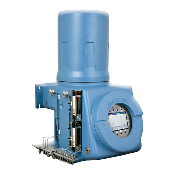
Gas chromatograph
Hide thumbs
Also See for Rosemount 700XA:
- Install (12 pages) ,
- Reference manual (294 pages) ,
- Reference manual (148 pages)

Subscribe to Our Youtube Channel
Related Manuals for Emerson Rosemount 700XA


Summary of Contents for Emerson Rosemount 700XA
- Page 1 Quick Start Guide MS-00825-0100-0700, Rev AA November 2023 Rosemount 700XA ™ Gas Chromatograph...
- Page 2 Quick Start Guide November 2023 Notice EMERSON (“SELLER”) SHALL NOT BE LIABLE FOR TECHNICAL OR EDITORIAL ERRORS IN THIS MANUAL OR OMISSIONS FROM THIS MANUAL. SELLER MAKES NO WARRANTIES, EXPRESSED OR IMPLIED, INCLUDING THE IMPLIED WARRANTIES OF MERCHANTABILITY AND FITNESS...
- Page 3 WARNING SAFETY COMPLIANCE The seller does not accept any responsibility for installations of the Rosemount 700XA Gas Chromatograph (GC) or any attached equipment in which the installation or operation thereof has been performed in a manner that is negligent and/or non-compliant with applicable safety requirements.
- Page 4 When handling the analyzer, always use suitable protective gloves. These precautions are particularly important when working at heights. If burned, seek medical treatment immediately. Emerson.com...
- Page 5 Check with your local authority or retailer for recycling advice. CAUTION The Rosemount 700XA is certified by the Canadian Standards Association (CSA) and ATEX. See the certification tag on the GC for specific details about its agency approvals. When the vapor regulators and flow switches are fitted, they must be suitably certified with the ratings Ex d IIC Gb T6/T4/T3 and for a minimum ambient temperature range: Ta = --4.0 °F (-20 °C) to 140.0 °F (60 °C).
- Page 6 Quick Start Guide November 2023 Installation and start-up ......................14 Hazardous area certifications (hardware dependent)............77 Emerson.com...
- Page 7 November 2023 Quick Start Guide 1 Cybersecurity recommendations for Rosemount XA gas chromatograph (GC) and MON2020 users Install XA GC in a secure environment with physical protection • Install the XA GC in a secure environment with physical protection. • Scan the USB shipped with the XA GC with anti-virus software before use.
- Page 8 Check integrity for distributed binaries • A hash value will be provided for some software/firmware files distributed by Emerson GC, so that the user can verify the integrity of the file. • The hashing algorithm SHA-256 is used for calculating the hash value of the binary file.
- Page 9 November 2023 Quick Start Guide • There are many programs for calculating the SHA-256 hash including Windows Command Prompt, Windows PowerShell, and third-party software (such as Hash Tool). The user can use a program of choice to calculate the SHA-256 hash value of the downloaded file and compare it to the value specified on the download page.
-
Page 10: Getting Started
November 2023 2 Getting started Emerson started and inspected your gas chromatograph (GC) before it left the factory. Emerson also installed program parameters and documented them in the GC Config Report furnished with your GC. 2.1 Select site The site you select for the gas chromatograph (GC) is important for measurement accuracy. - Page 11 Emerson Customer Care representative. Include the GC's model number in the report. Emerson will provide disposition instructions as soon as possible. If you have any questions regarding the claim process, contact your Emerson Customer Care representative for assistance.
- Page 12 Miscellaneous tube fittings, tubing benders, and tubing cutter • 14 American wire gauge (AWG) (18 metric wire gauge [MWG]) or larger electrical wiring and conduit to provide 120 or 240 Vac, single phase, 50 to 60 Hz, from an appropriate circuit breaker and power disconnect switch. Emerson.com...
- Page 13 Do not use a personal computer (PC) or printer in a hazardous area. Emerson provides serial and Ethernet communication links to connect the analyzer to the PC and to connect to other computers and printers in a safe area.
-
Page 14: Installation And Start-Up
(GC). In most cases, however, to install and set up a 700XA, Emerson recommends that you follow the instructions in the same order as they are presented in this manual. -
Page 15: Mounting Arrangements
November 2023 Quick Start Guide 3.2 Mounting arrangements The Rosemount 700XA can be installed in one of the following mounting arrangements: • Wall mount • Pole mount • Floor mount WARNING This device is heavy equipment. Two people are required to move the device. - Page 16 3.2.1 Mount the gas chromatograph (GC) to the wall The simplest mounting arrangement is the wall mount. If you specify Wall Mount on the sales order, Emerson will ship the GC with a wall mount installation kit. Four locations on the mounting ears are available for support.
- Page 17 3.2.2 Mount the gas chromatograph (GC) to a pole The pole mount arrangement uses an additional plate and spacers to allow the necessary clearance for nuts. If you specify Pole Mount on the sales order, Emerson will provide the necessary hardware. WARNING The GC is heavy and has a high potential of injuring personnel or damaging equipment.
- Page 18 7. Place the nuts with washers on the upper bolts and then tighten all bolts. 8. Adjust the lower bracket to align the bolts with the plate. Tighten the bolts. Emerson.com...
- Page 19 Quick Start Guide 3.2.3 Mount the gas chromatograph (GC) on the floor If you specify Floor Mount in the sales order, Emerson sends the floor mounting arrangement pre-assembled with the GC. The arrangement includes an additional support stand that is intended to be anchored to a floor or an instrument pad.
-
Page 20: Wiring Precautions
American Wire Gauge (AWG) sizes smaller than the conductors for the cable. Shielding is grounded at only one end. • Metal conduit or cable (according to local code) used for process signal wiring must be grounded at conduit support points, Emerson.com... - Page 21 (3 m) long, ¾-in. (19 mm) diameter steel rod, which is buried, full-length, vertically into the soil as close to the equipment as is practical. Note Emerson does not provide the grounding rod. Figure 3-4: Interior ground lug, lower enclosure • Resistance between the copper-clad steel ground rod and the earth ground must not exceed 25 Ohms.
-
Page 22: Grounding Precautions
(intermittent grounding of conduit helps prevent induction of magnetic loops between the conduit and cable shielding). • A single-point ground must be connected to a copper-clad, 10-ft. long, ¾-in. diameter (3 m long, 19.1 mm diameter) steel rod, Emerson.com... - Page 23 November 2023 Quick Start Guide which is buried, full-length, vertically into the soil as close to the equipment as is practical. NOTICE The grounding rod is not furnished. Figure 3-5: Interior ground lug, lower enclosure • Resistance between the copper-clad steel ground rod and the earth ground must not exceed 25 Ohms.
- Page 24 Failure to observe precautionary signs may result in serious injury or death to personnel. Observe all precautionary signs posted on the certified explosionproof equipment. Consult your company's polices and procedures and other applicable documents to determine wiring and installation practices that are appropriate for hazardous areas. Emerson.com...
- Page 25 November 2023 Quick Start Guide 3.3.5 Sample system requirements Line length If possible, avoid long sample lines. In long flow sample lines, velocity can be increased by decreasing downstream pressure and using bypass flow via a fast loop. Note Stream switching requires a sample pressure of 20 psig (1.4 barg).
-
Page 26: Electrical Installation
November 2023 3.4 Electrical installation NOTICE Emerson switches off central processing unit (CPU) boards before shipping to preserve their batteries. Before installing the CPU board, be sure to switch it on. Figure 3-6: CPU board A. SW7 battery power ON 3.4.1 ... - Page 27 November 2023 Quick Start Guide NOTICE Equipment damage Failure to observe this precaution may damage equipment. Check the gas chromatograph (GC) prior to wiring to determine if it is equipped for DC power. Procedure 1. Locate the plug-together termination block inside the electronics enclosure.
- Page 28 If the red (+) and black (-) leads are inadvertently reversed, no damage will occur; however, the system will not have power. 3. Connect the DC power leads to the power disconnect switch that should be properly fused. The recommended fuse size is 8 amps. Emerson.com...
- Page 29 November 2023 Quick Start Guide 3.4.2 Connect optional AC/DC power converter WARNING Failure to follow this warning may result in injury or death to personnel or cause damage to equipment. Check the gas chromatograph (GC) prior to wiring to determine if it is equipped for optional AC power.
- Page 30 AC wiring is usually color coded as: Label Wire color Hot (H) Brown or black Neutral (N) Blue or white Ground (G) Green with yellow tracer or green Emerson.com...
- Page 31 November 2023 Quick Start Guide 2. Bring the power leads in through the left entry on the bottom of the enclosure. 3. If necessary at remote locations, connect the GC chassis ground wire to an external copper ground rod. 3.4.3 Connect gas lines Quick Start Guide...
- Page 32 At this stage in the installation, the measure vent (MV) lines (labeled on the side of the GC) should remain plugged until the GC has been checked for leaks. For regular operation, however, the MV lines must be unplugged. Emerson.com...
- Page 33 November 2023 Quick Start Guide 2. Connect the carrier gas to the GC. The carrier gas inlet is labeled Carrier In and is a ¼-in. T-fitting. WARNING Leak testing All gas connections must be properly leak tested at installation. Do not turn on gas until you have completely checked the carrier lines for leaks.
- Page 34 Unless stated otherwise in the product documentation, ensure that the pressure of the calibration and sample line is regulated at 15 psig (1 barg) to 20 psig (1.4 barg). Postrequisites After all lines have been installed, proceed with leak-checking the carrier and sample lines. Emerson.com...
- Page 35 3.4.6 Installing and connecting to an analog modem card The Rosemount 700XA has two slots (input/output [I/O] Slot A and I/O Slot B) in the card cage for installing an analog modem.
- Page 36 (Label). 15. Set the Baud Rate for the analog modem card to 57600 16. Make note of the I/O slot’s Modbus ® 17. Click Save. 18. Click OK to close the Communication window. 19. Disconnect from the GC. Emerson.com...
- Page 37 November 2023 Quick Start Guide 3.4.7 Connect directly to a personal computer (PC) using the gas chromatograph's (GC’s) Ethernet1 port The GC’s dynamic host configuration protocol (DHCP) server feature and its Ethernet1 port on the backplane at J22 allows you to connect directly to the GC.
- Page 38 If you power cycle the GC, you will lose connectivity. 3.4.8 Connect to the gas chromatograph (GC) using Rosemount MON2020 To connect to the GC using the RJ45 Ethernet1 connection: Procedure 1. Start MON2020. The Connect to GC window displays. Emerson.com...
- Page 39 November 2023 Quick Start Guide 2. Locate the default Direct-DHCP under the GC Name column. This GC directory is created automatically when MON2020 is installed. You can rename the GC, but do not change the Internet protocol (IP) address that it references, 192.168.135.100 3.
- Page 40 If you are using a Ethernet straight-through cable, ensure that the personal computer (PC) has an Ethernet network interface card with auto-MDIX. b) If your Ethernet network interface card does not support auto-MDIX, ensure that you are using an Ethernet crossover patch cable. Emerson.com...
- Page 41 November 2023 Quick Start Guide c) Check to see if the GC's central processing unit (CPU) board link lights are on. Figure 3-13. The three Ethernet1 LEDs are located on the front bottom edge of the card. If link lights are off, check your connections. Figure 3-13: CPU board link lights A.
- Page 42 This is a useful feature for a GC that is located in an area without Internet access; all that is needed is a PC running Microsoft ® Windows , a notebook computer, and a straight-through serial cable. ™ Figure 3-14: J23 serial port A. J23 port Emerson.com...
- Page 43 Hardware Wizard. l) Click Finish. You return to the Phones and Modems screen. The Emerson Direct Connect modem should be listed in the Modem column. 2. Start MON2020 and do the following to create a GC connection for the Emerson Direct Connection modem: a) Go to File → ...
- Page 44 3.4.11 Connect directly to a personal computer (PC) using the gas chromatograph's (GC’s) wired Ethernet terminal The Rosemount 700XA has a wired Ethernet terminal at TB11 on the backplane that you can connect to with a static Internet protocol (IP) address.
- Page 45 November 2023 Quick Start Guide and a two-wire, twisted pair CAT5 Ethernet cable with one of its plugs removed to expose the wires. Figure 3-15: Crimped CAT5 cable Note The GC can be connected (or remain connected) to the local network on Ethernet2 (TB11) on the backplane while the dynamic host configuration protocol (DHCP) feature is being used.
- Page 46 CAT5 cable without the RJ45 plug. Figure 3-17: Field wiring to TB11 Figure 3-18: CAT5 wiring to TB11 2. Once you have wired the cable to the Ethernet terminal, plug the other end into a PC or a wall jack. Emerson.com...
- Page 47 November 2023 Quick Start Guide 3.4.12 Assign a static Internet protocol (IP) address to the gas chromatograph (GC) Procedure 1. Start Rosemount MON2020 and log in to the GC using a direct Ethernet connection. 2. Go to Application → Ethernet ports..The Ethernet Ports window displays.
- Page 48 This disables the dynamic host configuration (DHCP) server. 8. To connect to the GC: a) Start MON2020 and select File → GC Directory..The GC Directory window displays. b) Select Add. MON2020 adds a new GC profile to the end of the table. Emerson.com...
- Page 49 November 2023 Quick Start Guide Note You can name the GC’s profile as well as add a short description. c) Select the new profile and click Ethernet... Enter the GC’s static IP address in the IP address field. d) Click OK. The Ethernet Connection Properties for New GC window closes.
- Page 50 To connect digital signal input lines to the gas chromatograph (GC): Procedure 1. Disconnect power to the analyzer and allow the components to cool for at least five minutes. 2. Open the electronics enclosure door and access the backplane. Emerson.com...
- Page 51 November 2023 Quick Start Guide 3. Make the digital input wiring connections on the backplane at TB7. Figure 3-20: TB7 on the backplane Note The discrete digital input terminals on the backplane are self-powered. Devices connected to the digital input will be powered by the GC's dedicated isolated 24 V power supply.
- Page 52 1. Expose the end of the wire to a maximum length of ¼ in. (6.4 mm). NOTICE Emerson recommends twisted-pair cables for input/output (IO) signal wiring. The module's terminal blocks accept wire sizes between 12 and 22 American wire gauge (AWG). Allow some slack when making connections to prevent strain.
- Page 53 November 2023 Quick Start Guide Figure 3-21: Typical wiring A. Control B. Discrete device (externally powered) Table 3-3: ROC800 discrete digital wiring Terminal Label Definition Channel 1 Positive Channel 2 Positive Channel 3 Positive Channel 4 Positive Channel 5 Positive Channel 6 Positive Channel 7 Positive Channel 8 Positive...
- Page 54 TB3 connector. Table 3-4: Discrete digital outputs on TB3 Function Pin 1 Normally closed (NC1) DIG_OUT NC1 Pin 2 ARM1 DIG_OUT ARM1 Pin 3 Normally open (NO1) DIG_OUT NO1 Pin 4 DIG_OUT NC2 Pin 5 ARM 2 DIG_OUT ARM2 Emerson.com...
- Page 55 Optional discrete digital inputs (DI) When plugged into one of the optional card slots in the card cage, the Emerson ROC800 DI card provides eight additional discrete digital inputs. The discrete digital inputs can monitor the status of relays, open-collector or open-drain type solid-state switches, and other two-state devices.
- Page 56 Figure 3-23: Optional digital input/output (I/O) modules Wire an ROC800 digital output (DO) module Figure 3-24: Discrete digital output wiring A. Control B. Discrete device (externally powered) Terminal Label Definition Positive discrete output Discrete output return Positive discrete output Emerson.com...
- Page 57 2. Insert the exposed end into the clamp beneath the termination screw. 3. Tighten the screw. 3.4.14 Wiring the analog inputs All Rosemount 700XA gas chromatographs (GCs) have at least two analog inputs. An additional four analog inputs are available with an Quick Start Guide...
- Page 58 10 (TB10). Figure 3-25: TB10 on the backplane Table 3-5: Analog inputs TB10 Function Pin 1 +AI_1 Pin 2 -AI_1 Pin 3 +AI_2 Pin 4 -AI_2 Analog inputs settings switches Figure 3-26 shows how to wire two analog inputs (TB10). Emerson.com...
- Page 59 November 2023 Quick Start Guide Figure 3-26: Customer wiring for analog inputs A. Backplane B. Analog inputs C. Analog input 1 D. Analog input ground E. Analog input 2 F. Cable G. Customer devices H. Customer 4-20 mA outputs Figure 3-27 shows the factory settings for the analog input switches that are located on the base input/output (I/O) board.
- Page 60 To set the analog input to voltage, select Volts from the mA/Volts drop-down list for the appropriate analog input. 10. Click Save to save the changes and keep the window open or click OK to save the changes and close the window. Emerson.com...
- Page 61 November 2023 Quick Start Guide Typical wiring for line-powered transmitters Figure 3-28 shows the most common wiring plan for supplying power to two 4-20 mA transmitters, such as pressure sensor transmitters. Figure 3-28: Typical wiring for line-powered transmitters A. Backplane B.
- Page 62 Do not install or remove the printed circuit assemblies while power is applied to the device. Keep electrical components and assemblies in their protective (conductive) carriers or wrapping until ready for use. Use the protective carrier as a glove when installing or removing printed circuit assemblies. Emerson.com...
- Page 63 1. Expose the end of the wire to a maximum length of ¼ in. (6.4 mm). Note Emerson recommends twisted-pair cables for input/output (I/O) signal wiring. The module’s terminal blocks accept wire sizes between 12 and 22 American wire gauge (AWG). Allow some slack when making connections to prevent strain.
- Page 64 To calibrate the ROC800 AI-16 module you must have a personal computer (PC) with the ROCLINK 800 Configuration software installed ™ and open. See Emerson’s ROC800 Series page for details, downloads, and manuals. Procedure 1. Go to Configure → I/O → RTD Points → Calibration.
- Page 65 Quick Start Guide 3.4.15 Analog output wiring The Rosemount 700XA has at least six analog outputs. An additional four analog inputs are available with an ROC800 AO card that can be installed into one of the optional slots in the card cage.
- Page 66 Figure 3-32: Factory settings for analog output switches Wire customer externally-powered analog outputs It is possible to furnish power to each analog output while maintaining isolation between channels. Procedure Figure 3-33 to provide power wiring to each analog output while maintaining isolation between channels. Emerson.com...
- Page 67 November 2023 Quick Start Guide Figure 3-33: Wiring for customer-powered analog outputs A. Backplane B. Customer devices C. Analog outputs D. Inputs Figure 3-33 shows the settings for the analog outputs switches, located on the base input/output (I/O) board, that are necessary to provide power to each analog output while maintaining isolation between channels.
- Page 68 1. Expose the end of the wire to a maximum length of ¼ in. (6.4 Note Emerson recommends using twisted-pair cables for input/ output (I/O) signal wiring. The module’s terminal blocks accept wire sizes between 12 and 22 American wire gauge (AWG).
- Page 69 November 2023 Quick Start Guide 3.4.16 Configure analytical train Figure 3-35: Analytical Train Configuration window Procedure 1. Assign the usage of valves and DOs to each analyzer on the Hardware → Valves, Hardware → Detectors, and Hardware → Discrete Outputs screens. 2. Open the Application → Analytical Train Configuration screen. You can use the Filter Selections drop-down list to filter by the type of hardware you are interested in.
- Page 70 (GC) that has independent Sample Loop, Analytical Path, and Timed Event tables. Multiple analysis clocks can run independently to analyze multiple streams at the same time. Emerson sets the number of analysis clocks at the factory per the mechanical configurations of the GC. Mechanical...
- Page 71 November 2023 Quick Start Guide Mechanical Description configurations Energy Value If enabled, the GC analyzes the calibration gas as an Check unknown stream and computes its energy value. The GC then compares this value to the Cal Gas Cert CV and determines if the calibration gas's energy value is within the CV Check Allowed Deviation.
- Page 72 Note Refer to the analyzer's drawing documentation package that shipped with the GC for leak checking and identifying vents. Emerson tested the GC and fittings for leaks at the factory prior to shipment. Procedure 1. Plug the measure vent (labeled MV) vent line if it is open.
- Page 73 November 2023 Quick Start Guide Note Refer to the Flow Configuration schematic in the documentation packet that shipped with the GC for detailed instructions on plugging the flame ionization detector (FID) and flame photometric detector (FPD) vents. 3.5.2 Plugged lines, columns, and valves If the lines, columns, or valves are plugged, check the gas flow at valve ports.
- Page 74 Step 8 with the local operator interface (LOI). NOTICE Emerson recommends a continuous operation without sample gas for a period of four to eight hours (or overnight), during which no changes should be made to the settings described in Step 1 through Step 7.
- Page 75 November 2023 Quick Start Guide WARNING Safety compliance Failure to follow the safety instructions may cause injury to personnel. The seller does not accept any responsibility for installations of the device or any attached equipment in which the installation or operation thereof has been performed in a manner that is negligent and/or non-compliant with applicable safety requirements.
-
Page 76: Start Up The System
Unless stated otherwise in the product documentation, ensure that the pressure of the calibration and sample line is regulated at 10 to 30 psig (0.7 to 2.1 barg). Emerson recommends 15 psig (1 barg). c) Validate calibration gas and retention times and run a manual calibration. -
Page 77: Hazardous Area Certifications
November 2023 Quick Start Guide 4 Hazardous area certifications (hardware dependent) Logo Certification USA and Canada Class I, Zone 1, Ex/AEx db IIC Gb T6/T4/T3 Class I, Division 1, Groups, B, C, and D, IP66 EU ATEX and IECEx Ex db IIC Gb T6/T4/T3 Ta = -4 to +140 °F (-20 to +60 °C) SIRA 08ATEX 1328X IECEx SIR 09.0093X... - Page 78 Quick Start Guide November 2023 Emerson.com...
- Page 79 November 2023 Quick Start Guide Quick Start Guide...
- Page 80 2023 Emerson. All rights reserved. Emerson Terms and Conditions of Sale are available upon request. The Emerson logo is a trademark and service mark of Emerson Electric Co. Rosemount is a mark of one of the Emerson family of companies. All other marks are the property of their respective owners.
Need help?
Do you have a question about the Rosemount 700XA and is the answer not in the manual?
Questions and answers