Table of Contents
Advertisement
Quick Links
Advertisement
Table of Contents

Related Manuals for Emerson Dosaodor-D


Summary of Contents for Emerson Dosaodor-D
- Page 1 Instruction Manual Dosaodor-D D103671X012 October 2019 ODORANT INJECTION SYSTEM...
-
Page 2: Table Of Contents
Dosaodor-D SUMMARY: CHARACTERISTICS STARTUP / PROGRAMMING Electronic Control Unit ............3 Preliminary Checks ............. 25 Pneumatic Panel ..............4 Control Unit Power-on ............25 Product Description ............. 5 Programming Sequence ............. 26 Overall Dimensions ............6 Programmed / Displayed Data Table ........27 B1 Version Pneumatic Panel Parts List ...... -
Page 3: Characteristics
Injector failure (Primary) : Discrete Injector failure (Secondary, B.2 only) : Discrete Emergency circuit enabled : Discrete (Also indicates that the Dosaodor-D unit is in disabled mode) Odorant tank level : Discrete Instantaneous odorant concentration : Analog (4-20 mA) Daily odorant concentration... -
Page 4: Pneumatic Panel
Type PED Category Fluid Group The calibration cylinder tank is delivered already installed in the Dosaodor-D pneumatic panel (key 8 - figures 2 and 3). Dosaodor-D Article 3.3 - Cylinder 1” The pneumatic panel has been designed to hold calibration Calibration Cat. -
Page 5: Product Description
EEx areas odorizing liquid used, the maximum odorizing liquid capacity where there can be a risk of explosion. The Dosaodor-D and the maximum flow rate of the gas to be odorized. utilizes the high-pressure upstream gas as the pneumatic Table 1. -
Page 6: Overall Dimensions
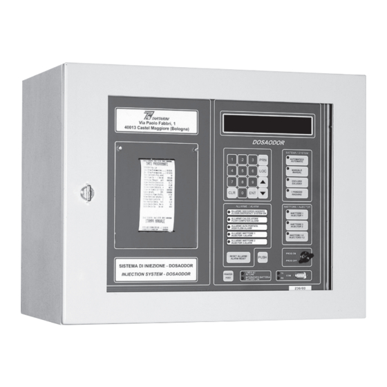
Dosaodor-D Overall Dimensions B2 Dual Injector Version B1 Single Injector Version 500 (19.7) 560 (22) 450 (17.7) 510 (20.1) 350 (13.8) Bracket 500 (19.7) Via Paolo Fabbri, 1 40013 Castel Maggiore (Bologna) DOSAODOR SISTEMA / SYSTEM AUTOMATICO AUTOMATIC MANUALE MANUAL... -
Page 7: B1 Version Pneumatic Panel Parts List
QUESTO IMPIANTO E' STATO REALIZZATO DA: THIS STATION HAS BEEN CONSTRUCTED BY: BOLOGNA ITALY OMT TARTARINI S.r.l.Via Paolo Fabbri,1 40013 Castelmaggiore BOLOGNA - ITALY TIPO N^FABBR. :DOSAODOR-D Rev. 1 TYPE SERIAL N^ Ball valve Pressione massima di comando : 100 Maximum drive pressure... -
Page 8: B2 Version Pneumatic Panel Parts List
THIS STATION HAS BEEN CONSTRUCTED BY: Level switch BOLOGNA ITALY OMT TARTARINI S.r.l.Via Paolo Fabbri,1 40013 Castelmaggiore BOLOGNA - ITALY TIPO N^FABBR. :DOSAODOR-D Rev. 1 TYPE SERIAL N^ Pressione massima di comando : 100 Maximum drive pressure Pressione massima di esercizio... -
Page 9: Atex Requirements
FAREGAZ Positions on ATEX Topics (see abstracts below), The Dosaodor-D odorizing system is classified as an “installation” according to clause 5.2.2 of the ATEX GUIDELINES - 4th Edition – September 2012 (see abstract below), therefore it’s not covered by Directive 2014/34/UE (ATEX I). -
Page 10: Installation
National safety standards and established the flow computer, to facilitate the connection of the cable rules shall be followed in odorizing system receiving signals from the Dosaodor-D during operation. installation and operation, concerning, Ground connections of the electronic control unit and... -
Page 11: Additional Materials Required
Dosaodor-D control unit and the flow computer. To complete installation the Dosaodor-D is provided with a kit of accessories needed for a standard system. c) Electrical cable with CEI 20-22-marked flameproof sheathing in the 1 x 4 size (yellow-green) to be used for... -
Page 12: Parts List
Dosaodor-D Parts List (see figures 4 and 5) Qty Description Connection 3/4” NPT-F Junction fitting (pipe-pipe) Junction fitting (pipe-pipe) Straight fitting DN 1/2” NPT-M Straight fitting DN 1/4” NPT-M Tap NAM 1/2” M-F Nipple 1/2” NPT-M Threaded tee fitting DN 1/2” NPT-F Ball valve DN 1/4”... - Page 13 Dosaodor-D Figure 4. Absorption Type Emergency System Installation Schematic...
-
Page 14: Odorant Filter Dimensions And Connections
Dosaodor-D Vent to Safe Area PRX/181 Figure 5. Injection Pressure > 6 bar (87 psi) Connection Schematic Detail (required only when the absorption type system is included) Odorant Filter (see figure 4, key 25) Dimensions and Connections Sec. A-A Liquid Outlet Liquid Inlet Figure 6. -
Page 15: Electrical Power Lines
For the installation of the electrical lines of the system, the gas line, and the odorant tank should be carried out please follow the indications provided for in “Dosaodor-D using stainless steel piping only, with diameters of 8x6 and Electric System Design” available on request and provisions 6x4 mm, respectively. - Page 16 Dosaodor-D Connect A13 with A15 Figure 7. Dosaodor-D B1 Version Electric Connections Schematic...
- Page 17 Dosaodor-D Connect A13 with A15 Figure 8. Dosaodor-D B2 Version Electric Connections Schematic...
- Page 18 Dosaodor-D Figure 9. Absorption Type Emergency Tank Connection Schematic Using a Volumetric Meter...
- Page 19 Dosaodor-D Figure 10. Absorption Type Emergency Tank Connection Schematic Using an Orifice (Venturimetric) Meter...
- Page 20 Dosaodor-D Figure 11. Absorption Type Emergency Tank with Storage Tank Connection Schematic Using Volumetric Meter...
- Page 21 Dosaodor-D Figure 12. Absorption Type Emergency Tank with Storage Tank Connection Schematic Using an Orifice (Venturimetric) Meter...
- Page 22 Dosaodor-D Figure 13. Storage Tank Without Absorption Type Emergency Tank Connection Schematic...
-
Page 23: User Available Signals
Terminals 6 & 14 of M4 - GCU Command – Pulse Signal to GCU Relay Terminals 7 & 15 of M4 - Control Run/Wait of Dosaodor-D SLAVE (Open = Run) Terminals 8 & 16 of M4 Analog output signals: The electrical specifications of the analog output signals are: - Range : 4 –... - Page 24 Dosaodor-D Ground Neutral Phase [EExi] BARRIER - ODORANT LEVEL DETECTOR GM 1030D 14(-) HI Level - Green wire of Level Detector Barrier 16(-) LOW Level - Brown wire of Level Detector 24V dc 13(+) / 15(+) Common - Bridge White wire of Level Detector...
-
Page 25: Startup / Programming
Storage Hi Pressure. 3= OFF GCU not present • Integrity of connections and equipment sealing 3= ON GCU Present – Dosaodor-D generate command for control GCU function • Status of painted surfaces. If paint is damaged any touch-ups must be carried out in accordance with the •... -
Page 26: Programming Sequence
Dosaodor-D The display will be lit and the first Programming page A “*” symbol will appear on the far right of the appears identified by LOC:00. appropriate line on the display if the displayed parameter is enabled for programming. It can be modified as follows: The displayed texts are in ENGLISH. -
Page 27: Programmed / Displayed Data Table
/h 00001000 * a) Volume for Injector Exchange a) Programmed Odorizing Rate Used in version Dosaodor-D B2 (dual injector) to set the grams of injected odorant after which the operating injec- Odorizing concentration that you intend to inject; it is tor is automatically exchanged. - Page 28 (which is normally installed). the internal Reloading Timer is reset. If after programming the Dosaodor-D set value it does not detect the High After each injection, the quantity inserted in the pipe is Odorant cylinder level, the Reloading Alarm is activated and subtracted.
- Page 29 Current Day Average Concentration The average concentration of odorant in the gas is displayed (ratio between the quantity of odorant injected Loc:10 Dosaodor-D Rev. 4.17 and the volume of transited gas) calculated between “Contractual Hour Day End” and current time.
- Page 30 * This value is indicated in letters “H” / “L” / “R” meaning: b) 2) PRINTING Daily Report “H” Dosaodor-D detect High Level inside of Control Cylinder By pressing key “2”, the daily report is printed. The “L” Dosaodor-D detect Low Level inside of Control Cylinder format is identical to the one used for the Automatic Report of the End of the Day.
-
Page 31: Programming Example
Dosaodor-D Programming Example DAILY DIAGNOSTIC Daily event type list. The codes are visible only on the The following represents an example for programming remote control software DosaLink. including explanatory notes. See paragraph “Programming Sequence” (Pag. 26) for an explanation of how to enter and modify data. - Page 32 Keep this value constantly monitored. If it The value to be set in the Dosaodor-D control unit must decreases, it means that the injection valve is getting be higher or equal to C” value calculated as above (it is dirty.
-
Page 33: Startup
(20 mA) that can be detected on the computer or gas flowrate transmitter. Set the min. threshold of odorant contained in the pickup tank. This value will enable the Dosaodor-D to switch off Loc:09 the contact for the low level odorant alarm. -
Page 34: Pneumatic Panel Startup
Locations from Loc:00 to Loc:05. Switch off the Dosaodor-D control unit. Verify the key is on In case of effective National regulations, above the “PROGRAMMING-ON” setting. Press ENT and keep it recommendation shall be mandatory. -
Page 35: Solenoid Injection Valve Setting Verification
Wash by means of Natural Gas • Close all valves on the pneumatic panel (key 27) Start the Dosaodor-D in AUTOMATIC with a gas flow at least 50% of the nominal. • Close the needle valve located on the pipe detecting the... -
Page 36: Washing By Means Of Natural Gas
(key 25A). dismantling of some parts by the operators. The odorant inside the Dosaodor-D system is placed inside the container. Remove the connection on the upper intake of the Only a min. quantity is injected into the line. -
Page 37: Activation Of The Modbus Communication
This technical note describes the procedures to adopt to acti- vate and configure the MODBUS communication protocol on the serial port/s on the Dosaodor-D Electronic Control Unit. installed with control Software Rev. 3.00 or equivalent. The MODBUS communication can be activated both on the Table 2. -
Page 38: Preliminary Operations
Dosaodor-D Preliminary Operations Select the location of Display 09 on the ECU and verify the position of the Dip Switch 4 indicated in the top left of the display with the caption Sw.4=ON/OFF. If the position of the Dip Switch 4 is ON, it is necessary to change it to OFF following below procedures: •... -
Page 39: Ecu Connections And Configuration
Dosaodor-D ECU Connections and Configuration The first operation is to create a connection between the If the serial cable has been connected to the right serial DosaLink Software and the ECU; in order to do this proceed port and if the configuration is correct, the DosaLink as follows: Software detects the Configuration present on the ECU. - Page 40 “COM Port 1”. The communication speed and the format of the data transmitted/received MUST be configured with the same values on both the Dosaodor-D ECU and the WARNING associated communication unit, Ex. RTU. In order to enable the MODBUS protocol it is necessary to select the “Protocol Type”...
- Page 41 “MODBUS COM Port 1” or “MODBUS COM Port 2” depending on the serial port to be configured. The MODBUS parameters need to be configured identically on both the ECU of the Dosaodor-D and on the RTU, both devices must use the same language in order to communicate.
-
Page 42: Modbus Communication Activation
Dosaodor-D MODBUS Communication Activation Once the configurations described item 3) have been completed, to activate the MODBUS the following operations must be performed: If the Modbus Communication has been activated on the Serial Port “COM Port 2” of the ECU (Serial Port... - Page 43 Dosaodor-D...
- Page 44 D103671X012 © 2017, 2019 Emerson Process Management Regulator Technologies, Inc. All rights reserved. 10/19. Americas Asia Pacific The Emerson logo is a trademark and service mark of Emerson Electric McKinney, Texas 75070 USA Singapore 128461, Singapore Co. All other marks are the property of their prospective owners.
Need help?
Do you have a question about the Dosaodor-D and is the answer not in the manual?
Questions and answers