Table of Contents
Advertisement
Quick Links
Warranty
All products manufactured by ICP DAS are under warranty
regarding defective materials for a period of one year, beginning
from the date of delivery to the original purchaser.
Warning!
ICP DAS assumes no liability for any damage resulting
from the use of this product. ICP DAS reserves the right to
change this manual at any time without notice. The information
furnished by ICP DAS is believed to be accurate and reliable.
However, no responsibility is assumed by ICP DAS for its use,
not for any infringements of patents or other rights of third
parties resulting from its use.
Copyright
Copyright @ 2007 by ICP DAS Co., Ltd. All rights are
reserved.
Trademark
The names used for identification only may be registered
trademarks of their respective companies.
M-7065 User's Manual Ver2.0, Dec. /200 8 ---1
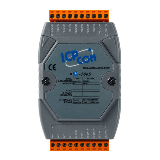
M-7065
User Manual
Advertisement
Table of Contents

Related Manuals for ICP DAS USA M-7065


Summary of Contents for ICP DAS USA M-7065
- Page 1 Copyright Copyright @ 2007 by ICP DAS Co., Ltd. All rights are reserved. Trademark The names used for identification only may be registered trademarks of their respective companies. M-7065 User’s Manual Ver2.0, Dec. /200 8 ---1...
-
Page 2: Table Of Contents
2.8 $AA2 ......................38 2.9 $AA4 ......................40 2.10 $AA5 ......................43 2.11 $AA6 ......................45 2.12 $AAC ......................47 2.13 $AACN ......................49 2.14 $AAF ......................51 2.15 $AALS ......................53 2.16 $AAM......................56 M-7065 User’s Manual Ver2.0, Dec. /200 8 ---2... - Page 3 3.5 05(0x05) Write single coils ................. 110 3.6 06(0x06) Write multiple registers ..............114 3.7 15(0x0F) Write multiple coils ..............116 3.8 46(0x46) Read/Write module settings ............. 119 3.8.1 00(0x00) Read Module Name .............. 120 M-7065 User’s Manual Ver2.0, Dec. /200 8 ---3...
- Page 4 4. Modbus ASCII Protocol ................141 A. Appendix ......................143 A.1 INIT Mode ....................143 A.2 Dual Watchdog operation................144 A.3 Reset Status ....................145 A.4 Digital Output .................... 146 A.5 Latched Digital Input ................. 147 M-7065 User’s Manual Ver2.0, Dec. /200 8 ---4...
-
Page 5: Introduction
M-7000 series offers extended support for the Modbus RTU protocol. The I-7000 and M-7000 DIO modules support TTL signal,photo-isolated digital input, AC voltage digital input, relay contact output, solid-state relay output, photoMOS output and open-collector output. M-7065 User’s Manual Ver2.0, Dec. /200 8 ---5... -
Page 6: More Information
1.1 More Information For more information regarding the I-7000 series, please refer to chapter 1 of the “I-7000 Bus Converter User’s Manual” as shown below or visit the ICP DAS website http://www.icpdas.com. M-7065 User’s Manual Ver2.0, Dec. /200 8 ---6... -
Page 7: Pin Assignment
1.2 Pin Assignment M-7065 User’s Manual Ver2.0, Dec. /200 8 ---7... -
Page 8: Specifications
Baud Rate 1200 ~ 115200bps LED Display 1 LED as Power/ Communication indicator 4 LEDs as Digital Input indicators and 5 LEDs as Relay Output indicators (for I-7065D) Power Input Voltage Range 10~30VDC M-7065 User’s Manual Ver2.0, Dec. /200 8 ---8... -
Page 9: Block Diagram
Operating Temperature -25 to 75° C Storage Temperature -40 to 85° C Humidity 5 to 95%, non-condensing Ordering information M-7065 4-channel Isolated Digital Input and 5-channel Relay Output Module with 16-bit Counters 1.4 Block Diagram M-7065 M-7065 User’s Manual Ver2.0, Dec. /200 8 ---9... -
Page 10: Wire Connection
1.5 Wire Connection Dry Contact TTL/CMOS Input Type NPN Output PNP Output Relay Collector Relay ON Relay OFF Output Type M-7065 User’s Manual Ver2.0, Dec. /200 8 ---10... -
Page 11: Quick Start
1.6 Quick Start This Quick Start document describes the methods used to quickly set up and test the M-7065 using the ICP DAS DCON Utility. After confirming that the module is operational, more applications or software support be found by referring to the following links: For Win32: ftp://ftp.icpdas.com/pub/cd/8000cd/napdos/driver/dcon_utility/... - Page 12 All ICPDAS I/M-7000 modules supported by the current version of the DCON utility software that are currently connected to the RS-485 network will be listed in this area. M-7065 User’s Manual Ver2.0, Dec. /200 8 ---12...
- Page 13 How do I set the configuration of the modules ? ICP DAS M-7065 DIO module are command based. A series of commands are provided to allow the configuration and DI/O functions to be set. The basic DI/O and configuration commands are listed below.
- Page 14 Data [LRC] CR LF Character Address Using Modbus ASCII Protocol, all command are coded in hexadecimal values, represented with readable ASCII characters. Only the characters 0...9 and A...F are used for coding. M-7065 User’s Manual Ver2.0, Dec. /200 8 ---14...
- Page 15 Modbus ASCII => :014600B9(CR•LF) (1.) hexadecimal = 01h+46h+00h = 47h (2.) 2’s complement: = B9h (LRC) Technical Support If you have problems about using the M-7065 DIO module, please contact ICP DAS Product Support. Email: Service@icpdas.com M-7065 User’s Manual Ver2.0, Dec. /200 8 ---15...
-
Page 16: Default Settings
Parity Baud Rate Code (bit0~bit5) Code Baud 1200 2400 4800 9600 19200 38400 57600 115200 Rate Type Code (TT) For M-7065 DIO modules, the type code is fixed to 40 M-7065 User’s Manual Ver2.0, Dec. /200 8 ---16... -
Page 17: Di/O Data Format Table
(the First Data)(the Second Data). Note: both the First Data and the Second Data are in two hexadecimal digits format. Module The First Data The Second Data M-7065 DO0-DO5 00~1F DI0-DI3 00~0F M-7065 User’s Manual Ver2.0, Dec. /200 8 ---17... -
Page 18: Dcon Protocol
Leading Module Data [CHKSUM] Character Address CHKSUM 2-character checksum which is present when the checksum setting is enabled.See Sections 1.1 (Data Format Setting) for details. End of command character, carriage return (0x0D) M-7065 User’s Manual Ver2.0, Dec. /200 8 ---18... - Page 19 “!”+”0”+”1”+”2”+”0”+”0”+”6”+”0”+”0” = 21h+30h+31h+32h+30h+30h+36h+30h+30h = 1AAh 2. Therefore the checksum is AAh, and so CHKSUM = “AA” 3. The response string with the checksum = !01200600AA(CR) Note: All characters should be in upper case. M-7065 User’s Manual Ver2.0, Dec. /200 8 ---19...
- Page 20 Sets the Module Name 2.22 ~AAD !AAF Reads the DI/O active status. 2.23 ~AADVV Sets the DI/O active status. 2.24 ~AAI Sets the soft INIT 2.25 ~AATnn Set the soft INIT timeout value M-7065 User’s Manual Ver2.0, Dec. /200 8 ---20...
- Page 21 Sets the Timeout Settings 2.31 ~AA4V !AA(Data) Reads the PowerOn/Safe Value 2.32 ~AA5V Sets the PowerOn/Safe Value 2.33 ~AARDvv Sets the Response Delay Time 2.34 ~AARD !AA(Data) Reads the Response Delay Time M-7065 User’s Manual Ver2.0, Dec. /200 8 ---21...
-
Page 22: Aannttccff
Used to set the counter update direction and checksum (Section 1.1). Response: Valid Command: !AA[CHKSUM](CR) Invalid Command: ?AA[CHKSUM](CR) Delimiter for a valid command. Delimiter for an invalid command. Address of the module in hexadecimal format (00 to FF) M-7065 User’s Manual Ver2.0, Dec. /200 8 ---22... - Page 23 FF (Sets the counter update) 80 : Sets the counter update (Rising Edge) 00 : Sets the counter update (Falling Edge) Related Commands: Section 2.8 $AA2、2.24 ~AAI、2.25 ~AATnn Related Topics: Section 1.1 Configuration Tables M-7065 User’s Manual Ver2.0, Dec. /200 8 ---23...
- Page 24 There is no response with this command. To access the data, another command, $AA4, must be sent, see Section 2.11 for details. Examples: Command:#** Response: No response Sends the synchronized sampling command. Command:$014 Response:!10C0300 M-7065 User’s Manual Ver2.0, Dec. /200 8 ---24...
- Page 25 NOT the first time the synchronized data has been read after the previous #** command. Digital Output : 0x0C Digital Input : 0x03 Related Commands: Section 2.9 $AA4 M-7065 User’s Manual Ver2.0, Dec. /200 8 ---25...
-
Page 26: Aa00(Data)
Response: >[CHKSUM](CR) Valid Command: ?AA[CHKSUM](CR) Invalid Command: Ignored Command:  > Delimiter for a valid command. Delimiter for an invalid command. Ignored Delimiter character. M-7065 User’s Manual Ver2.0, Dec. /200 8 ---26... - Page 27 Response:> Sets DO0、DO3 to off,DO1、DO2 to on, and the module returns a valid response. Command:#010016 Response:> Sets DO0、DO3 to off,DO1、DO2 to on DO6、DO7、DO8 to off,DO5 to on Command:#010005 Response:! Host Watchdog Timeout. M-7065 User’s Manual Ver2.0, Dec. /200 8 ---27...
- Page 28 Related Commands: Section 2.4 #AA0A(Data)、2.5 #AA1cDD 2.6#AAAcDD、2.11 $AA6、2.19 @AA 2.20 @AA(Data) M-7065 User’s Manual Ver2.0, Dec. /200 8 ---28...
-
Page 29: Aa0A(Data)
DO0, bit 1 corresponds to DO1, etc. When the bit is 1, it denotes that the digital output channel is on, and 0 denotes that the digital output channel is off. M-7065 User’s Manual Ver2.0, Dec. /200 8 ---29... - Page 30 There will be no response if the command syntax is incorrect, there is a communication error, or there is no module with the specified address. Examples: Command:#010A0E Response:> Sets DO0 to off,DO1、DO2、DO3 to on. Command:#010A06 Response:! Host Watchdog Timeout. M-7065 User’s Manual Ver2.0, Dec. /200 8 ---30...
- Page 31 Command:#010A0F Response:> Sets DO0、DO1、DO2、DO3 to on. Command:#020A00 Response:> Sets DO0、DO1、DO2、DO3 to off. Related Commands: Section 2.3 #AA00(Data)、2.5 #AA1cDD 2.6#AAAcDD、2.11 $AA6、2.19 @AA 2.20 @AA(Data) M-7065 User’s Manual Ver2.0, Dec. /200 8 ---31...
-
Page 32: Aa1Cdd
01 : set the digital output channel to on. Response: Valid Command: >[CHKSUM](CR) ?AA[CHKSUM](CR) Invalid Command: Ignored Command:  > Delimiter for a valid command. Delimiter for an invalid command. Ignored Delimiter character M-7065 User’s Manual Ver2.0, Dec. /200 8 ---32... - Page 33 Examples: Command:#021001 Response:> Sets DO0 to on. Command:#021401 Response:> Command:#021301 Response:> Sets DO3 to on. Related Commands: Section 2.3 #AA00(Data)、2.4 #AA0A(Data) 2.6#AAAcDD、2.11 $AA6、2.19 @AA 2.20 @AA(Data) M-7065 User’s Manual Ver2.0, Dec. /200 8 ---33...
-
Page 34: Aaacdd
Specifies the digital output channel to be set. (0-7) 00 : set the digital output channel to off. 01 : set the digital output channel to on. Response: Valid Command: >[CHKSUM](CR) Invalid Command: ?AA[CHKSUM](CR) Ignored Command:  M-7065 User’s Manual Ver2.0, Dec. /200 8 ---34... - Page 35 Examples: Command:#02A201 Response:> Sets DO2 to on Related Commands: Section 2.3 #AA00(Data)、2.4 #AA0A(Data) 2.5 #AA1cDD、2.11 $AA6、2.19 @AA 2.20 @AA(Data) M-7065 User’s Manual Ver2.0, Dec. /200 8 ---35...
-
Page 36: Aan
An invalid command is returned if the specified channel is incorrect. (Data) Five decimal digits representing the digital input counter data of the specified channel (00000 to 65535). Address of the responding module (00 to FF) M-7065 User’s Manual Ver2.0, Dec. /200 8 ---36... - Page 37 Reads data from channel 1 of module 01 and the returned counter value is 00005. Command:#015 Response:!0100005 Reads data from channel 5 of module 01 and the returned counter value is 00005. Related Commands: Section 2.13 #AACN M-7065 User’s Manual Ver2.0, Dec. /200 8 ---37...
-
Page 38: Aa2
Type code of the module, should be 40 for DIO module. Baud Rate code of the module,should be 0A Checksum and counter update direction settings of the module, see Section 1.1 for details. M-7065 User’s Manual Ver2.0, Dec. /200 8 ---38... - Page 39 Command:$012 Response:!01400AC0 Reads the configuration of module 01. FF (Sets the counter update) C0 : Reads the counter update (Rising Edge), checksum enabled. Related Commands: Section 2.1 %AANNTTCCFF Related Topics: Section 1.1 M-7065 User’s Manual Ver2.0, Dec. /200 8 ---39...
-
Page 40: Aa4
Delimiter for an invalid command. Address of the responding module (00 to FF) Status of the synchronized data 1:first read 0:not the first read (Data) Synchronized data. See Section 1.2 for the data format. M-7065 User’s Manual Ver2.0, Dec. /200 8 ---40... - Page 41 Reads the synchronized data for module 01. The module returns the synchronized data and sets thestatus byte to 0 to indicate that the synchronized data has been read Digital Output : 0x05 Digital Input : 0x3F M-7065 User’s Manual Ver2.0, Dec. /200 8 ---41...
- Page 42 Related Commands: Section 2.2 #** M-7065 User’s Manual Ver2.0, Dec. /200 8 ---42...
-
Page 43: Aa5
0:This is not the first time the command has been sent since the module was powered on, which denotes that there has been no module reset since the last $AA5 command was sent. M-7065 User’s Manual Ver2.0, Dec. /200 8 ---43... - Page 44 Command:$015 Response:!010 Reads the reset status of module 01. The response shows that there has been no module reset since the last $AA5 command was sent. M-7065 User’s Manual Ver2.0, Dec. /200 8 ---44...
-
Page 45: Aa6
00. See Section 1.2 for details. There will be no response if the command syntax is incorrect, there is a communication error, or there is no module with the specified address. M-7065 User’s Manual Ver2.0, Dec. /200 8 ---45... - Page 46 01. Digital Output : 0x1F Command:$016 Response:!070F00 Reads the digital input/output channel status of module 01. Digital Output : 0x07 Digital Iutput : 0x0F Related Commands: Section 2.3 #AA00(Data)、2.4 #AA0A(Data) 2.5 #AA1cDD、2.6 #AAAcDD、2.19 @AA 2.20 @AA(Data) M-7065 User’s Manual Ver2.0, Dec. /200 8 ---46...
-
Page 47: Aac
Address of the responding module (00 to FF) There will be no response if the command syntax is incorrect, there is a communication error, or there is no module with the specified address. M-7065 User’s Manual Ver2.0, Dec. /200 8 ---47... - Page 48 Sends the command to read the status of the low latched digital input channels of module 01. Low Latched DI : 0x3F Low Latched DO : 0x09 Related Commands: Section 2.15 $AALS M-7065 User’s Manual Ver2.0, Dec. /200 8 ---48...
-
Page 49: Aacn
Address of the responding module (00 to FF) There will be no response if the command syntax is incorrect, there is a communication error, or there is no module with the specified address. M-7065 User’s Manual Ver2.0, Dec. /200 8 ---49... - Page 50 Clears the counter value of channel 1 of module 01 and returns a valid response. Command:#011 Response:!0100000 Reads counter data from channel 1 of module 01 and the returned counter value is 0. Related Commands: Section 2.7 #AAN M-7065 User’s Manual Ver2.0, Dec. /200 8 ---50...
-
Page 51: Aaf
(Data) Firmware version string of the module There will be no response if the command syntax is incorrect, there is a communication error, or there is no module with the specified address. M-7065 User’s Manual Ver2.0, Dec. /200 8 ---51... - Page 52 Examples: Command:$01F Response:!0102.00 Reads the firmware version of module 01, and shows that it is version 02.00. M-7065 User’s Manual Ver2.0, Dec. /200 8 ---52...
-
Page 53: Aals
Delimiter for an invalid command. Address of the responding module (00 to FF) (Data) Status of the latched digital input channels, a four- digit hexadecimal value followed by 00. See Section 1.2 for details. M-7065 User’s Manual Ver2.0, Dec. /200 8 ---53... - Page 54 Command:$01L0 Response:!093F00 Sends the command to read the status of the low latched digital input channels of module 01. Low Latched DI : 0x3F Low Latched DO : 0x09 M-7065 User’s Manual Ver2.0, Dec. /200 8 ---54...
- Page 55 Sends the command to read the status of the high latched digital input channels of module 01. High Latched DI : 0x00 High Latched DO : 0x06 Related Commands: Section 2.12 $AAC Related Topics: Section M-7065 User’s Manual Ver2.0, Dec. /200 8 ---55...
-
Page 56: Aam
Address of the responding module (00 to FF) (Data) Name string of the module There will be no response if the command syntax is incorrect, there is a communication error, or there is no module with the specified address. M-7065 User’s Manual Ver2.0, Dec. /200 8 ---56... - Page 57 Command:$01M Response:!017065 Reads the module name of module 01 and returns the name. Related Commands: Section 2.21 ~AAO(Name) M-7065 User’s Manual Ver2.0, Dec. /200 8 ---57...
-
Page 58: Aap
The protocols supported by the module 0: DCON 1: DCON and Modbus RTU 3: DCON and Modbus RTU/ASCII The current protocol that is saved in the EEPROM that will be used at the next power-on reset M-7065 User’s Manual Ver2.0, Dec. /200 8 ---58... - Page 59 01 and returns a response of 30 meaning that it supports the DCON and Modbus RTU/ASCII protocols and the protocol that will be used at the next power-on reset is DCON. Related Commands: Section 2.18 $AAPN M-7065 User’s Manual Ver2.0, Dec. /200 8 ---59...
-
Page 60: Aapn
Address of the responding module (00 to FF) There will be no response if the command syntax is incorrect, there is a communication error, or there is no module with the specified address. Examples: M-7065 User’s Manual Ver2.0, Dec. /200 8 ---60... - Page 61 Modbus RTU and returns an invalid response because the module is not in INIT mode. Command:$01P1 Response:!01 Sets the communication protocol of module 01 to Modbus RTU and returns a valid response. Related Commands: Section 2.17 $AAP M-7065 User’s Manual Ver2.0, Dec. /200 8 ---61...
- Page 62 See Section 1.2 for details. There will be no response if the command syntax is incorrect, there is a communication error, or there is no module with the specified address. M-7065 User’s Manual Ver2.0, Dec. /200 8 ---62...
- Page 63 RL1, RL2, RL3 and RL4 are on and IN1, IN2, IN3 and IN4 are on . Related Commands: Section 2.3 #AA00(Data)、2.4 #AA0A(Data) 2.5 #AA1cDD、2.6 #AAAcDD、2.11 $AA6 2.20 @AA(Data) Related Topics: Section 1.2 M-7065 User’s Manual Ver2.0, Dec. /200 8 ---63...
-
Page 64: Aa(Data)
0 denotes that the digital output channel is off. Response: Valid Command: >[CHKSUM](CR) ?AA[CHKSUM](CR) Invalid Command: Ignored Command:  > Delimiter for a valid command. Delimiter for an invalid command. Ignored Delimiter character M-7065 User’s Manual Ver2.0, Dec. /200 8 ---64... - Page 65 Examples: Command:@02F Response:> Sets DO0、DO1、DO2、DO3 to on. Related Commands: Section 2.3 #AA00(Data)、2.4 #AA0A(Data)、 2.5 #AA1cDD、2.6#AAAcDD、2.11 $AA6、2.19 @AA M-7065 User’s Manual Ver2.0, Dec. /200 8 ---65...
-
Page 66: Aao(Name)
Address of the responding module (00 to There will be no response if the command syntax is incorrect, there is a communication error, or there is no module with the specified address. M-7065 User’s Manual Ver2.0, Dec. /200 8 ---66... - Page 67 7065. Command:~01OM7065 Response:!01 Sets the name of module 01 to be “ M7065” and returns a valid response. Command:$01M Response:!01M7065 Reads the name of module 01 and returns the name M7065. M-7065 User’s Manual Ver2.0, Dec. /200 8 ---67...
-
Page 68: Aad
A two-digit hexadecimal value indicating the DI/O active status. There will be no response if the command syntax is incorrect, there is a communication error, or there is no module with the specified address. M-7065 User’s Manual Ver2.0, Dec. /200 8 ---68... - Page 69 1 for non-signal or the low voltage; input value 0 for high voltage input value 0 for non-signal or the low voltage; input value 1 for high voltage (DI/O Active Status) Related Commands: Section 2.23 ~AADVV M-7065 User’s Manual Ver2.0, Dec. /200 8 ---69...
-
Page 70: Aadvv
Address of the responding module (00 to There will be no response if the command syntax is incorrect, there is a communication error, or there is no module with the specified address. M-7065 User’s Manual Ver2.0, Dec. /200 8 ---70... - Page 71 1 for non-signal or the low voltage; input value 0 for high voltage input value 0 for non-signal or the low voltage; input value 1 for high voltage Related Commands: Section 2.22 ~AAD M-7065 User’s Manual Ver2.0, Dec. /200 8 ---71...
-
Page 72: Aai
Address of the responding module (00 to There will be no response if the command syntax is incorrect, there is a communication error, or there is no module with the specified address. M-7065 User’s Manual Ver2.0, Dec. /200 8 ---72... - Page 73 Set the soft INIT time out value of module 01 to 16 seconds and returns a valid response. Command:~03I Response:!03 Set the Soft INIT of module 01 and return a valid response. M-7065 User’s Manual Ver2.0, Dec. /200 8 ---73...
- Page 74 Attempts to change the Baud Rate of module 01 to 19200 without first adjusting the INIT * pin.The module returns an in valid response. Related Commands: : : : Section 2.25 ~AATnn M-7065 User’s Manual Ver2.0, Dec. /200 8 ---74...
-
Page 75: Aatnn
Delimiter for an invalid command. Address of the responding module There will be no response if the command syntax is incorrect, there is a communication error, or there is no module with the specified address. M-7065 User’s Manual Ver2.0, Dec. /200 8 ---75... - Page 76 Informs all modules that the host is OK. Syntax: ~** [CHKSUM](CR) Delimiter character Host OK command Response: No response Examples: Command: ~** Response: No response Related Commands: Section 2.27 ~AA0、2.28 ~AA1、2.29 ~AA2 2.30 ~AA3EVV、2.31 ~AA4V、 2.32 ~AA5V M-7065 User’s Manual Ver2.0, Dec. /200 8 ---76...
-
Page 77: Aa0
Bit 7: 0 indicates that the host watchdog is disabled, and 1 indicates that the host watchdog is enabled, Bit 2: 1 indicates that a host watchdog timeout has occurred, and 0 indicates that no host watchdog timeout has occurred. M-7065 User’s Manual Ver2.0, Dec. /200 8 ---77... - Page 78 04, meaning that a host watchdog timeout has occurred. Command:~030 Response:!0300 Reads the host watchdog status of module 03 and returns 00, meaning that the host watchdog is disabled and no host watchdog timeout has occurred. M-7065 User’s Manual Ver2.0, Dec. /200 8 ---78...
- Page 79 Reads the host watchdog status of module 03 and returns 08, meaning that the host watchdog is enabled. Sents ~** to clear watchdog timeout value. Related Commands: Section 2.26 ~**、2.28 ~AA1、2.29 ~AA2 2.30 ~AA3EVV、2.31 ~AA4V、 2.32 ~AA5V M-7065 User’s Manual Ver2.0, Dec. /200 8 ---79...
-
Page 80: Aa1
Address of the responding module (00 to There will be no response if the command syntax is incorrect, there is a communication error, or there is no module with the specified address. M-7065 User’s Manual Ver2.0, Dec. /200 8 ---80... - Page 81 Command:~031 Response:!03 Resets the host watchdog timeout status of module 03 and returns a valid response. Related Commands: Section 2.26 ~**、2.27 ~AA0、2.29 ~AA2 2.30 ~AA3EVV、2.31 ~AA4V、 2.32 ~AA5V M-7065 User’s Manual Ver2.0, Dec. /200 8 ---81...
-
Page 82: Aa2
1: the host watchdog is enabled 0: the host watchdog is disabled Two hexadecimal digits to represent the timeout value in tenths of a second, for example, 01 denotes 0.1 seconds and FF denotes 25.5 seconds. M-7065 User’s Manual Ver2.0, Dec. /200 8 ---82... - Page 83 03 and returns 0x90, which denotes that the host watchdog is enabled and the host watchdog timeout value is 14.4 seconds Related Commands: Section 2.26 ~**、2.27 ~AA0、2.28 ~AA1 2.30 ~AA3EVV、2.31 ~AA4V、 2.32 ~AA5V M-7065 User’s Manual Ver2.0, Dec. /200 8 ---83...
-
Page 84: Aa3Evv
01 denotes 0.1 seconds and FF denotes 25.5 seconds. Response: !AA[CHKSUM](CR) Valid Command: Invalid Command: ?AA[CHKSUM](CR) Delimiter for a valid command. Delimiter for an invalid command. Address of the responding module (00 to M-7065 User’s Manual Ver2.0, Dec. /200 8 ---84... - Page 85 01. The module returns 164, which denotes that the host watchdog is enabled and the host watchdog timeout value is 10.0 seconds. Related Commands: Section 2.26 ~**、2.27 ~AA0、2.28 ~AA1 2.29 ~AA2、2.31 ~AA4V、 2.32 ~AA5V M-7065 User’s Manual Ver2.0, Dec. /200 8 ---85...
-
Page 86: Aa4V
(Data) Power On Value or Safe Value There will be no response if the command syntax is incorrect, there is a communication error, or there is no module with the specified address. M-7065 User’s Manual Ver2.0, Dec. /200 8 ---86... - Page 87 Examples: Command:~034P Response:!030700 Reads the power-on DO value of module 03 and returns 0700. Command:~034S Response:!030F00 Reads the safe DO value of module 03 and returns 0F00. Related Commands: Section 2.32 ~AA5V M-7065 User’s Manual Ver2.0, Dec. /200 8 ---87...
-
Page 88: Aa5V
Address of the responding module (00 to There will be no response if the command syntax is incorrect, there is a communication error, or there is no module with the specified address. M-7065 User’s Manual Ver2.0, Dec. /200 8 ---88... - Page 89 Sets DO0、DO1、DO2、DO3 to on Command:~035S Response:!03 Sets the safe DO value and the module returns a valid response. Command:~034S Response:!030F00 Reads the safe DO value of module 03. Related Commands: Section 2.31 ~AA4V M-7065 User’s Manual Ver2.0, Dec. /200 8 ---89...
-
Page 90: Aardvv
Address of the responding module (00 to There will be no response if the command syntax is incorrect, there is a communication error, or there is no module with the specified address. M-7065 User’s Manual Ver2.0, Dec. /200 8 ---90... - Page 91 Examples: Command:~03RD1E Response:!03 Sets the Response Delay Time, the value is 1E. (30ms) Command:~03RD Response:!0300 Reads the Response Delay Time, the value is 00. (0ms). Related Commands: Section 2.34 ~AARD M-7065 User’s Manual Ver2.0, Dec. /200 8 ---91...
-
Page 92: Aard
Address of the responding module(00 to FF) (Data) Response Delay Time Value There will be no response if the command syntax is incorrect, there is a communication error, or there is no module with the specified address. M-7065 User’s Manual Ver2.0, Dec. /200 8 ---92... - Page 93 Examples: Command:~03RD1E Response:!03 Sets the Response Delay Time, the value is 1E. (30ms) Command:~03RD Response:!0300 Reads the Response Delay Time, the value is 00. (0ms). Related Commands: Section 2.33 ~AARDvv M-7065 User’s Manual Ver2.0, Dec. /200 8 ---93...
-
Page 94: Modbus Rtu Protocol
00: no parity, 1 stop bit 10: even parity, 1 stop bit 11: odd parity, 1 stop bit 00264 Clear Latched DI/O 00513 Clear DI Count 40481 Firmware version (low word) 40482 Firmware version (high word) M-7065 User’s Manual Ver2.0, Dec. /200 8 ---94... - Page 95 Informs all modules that the host is OK Modbus RTU Function Description: (0xxxx) : 0x01、0x05、0x0F Function code (1xxxx) : 0x02 Function code (3xxxx) : 0x04 Function code (4xxxx) : 0x03、0x03、0x10 Function code Address mapping of PLC(Base 1). M-7065 User’s Manual Ver2.0, Dec. /200 8 ---95...
- Page 96 Protocol(Base 0). Error Response Address 1 Byte 1 to 247 Function code 1 Byte Function code + 0x80 Exception code 1 Byte If a CRC mismatch occurs, the module will not respond. M-7065 User’s Manual Ver2.0, Dec. /200 8 ---96...
-
Page 97: 0X01) Read Coils
0x0103 Reads WDT Enable : 0x0104 Reads WDT Status : 0x010D Reads Protocol : 0x0100 Reads Reset Status : 0x0110 Output channel number 0x0001-0x0020 04-05 2 Byte or bit count (Bit count) M-7065 User’s Manual Ver2.0, Dec. /200 8 ---97... - Page 98 Byte 6~7 : FD 8D(CRC) [Response] Byte 1 : 01 (Function Code) Byte 2 : 01 (Byte count of response) Byte 3 : 1F (DO0~DO3 Value) Byte 4~5 : 11 70 (CRC) M-7065 User’s Manual Ver2.0, Dec. /200 8 ---98...
- Page 99 Response:05 01 01 00 50 B8 Resets the host watchdog timeout status of a module Command:05 01 01 00 00 09 [ 6C 71 ] Response:05 01 02 01 00 49 AC Reads protocol of module M-7065 User’s Manual Ver2.0, Dec. /200 8 ---99...
- Page 100 Supported modules : M-7065 DO : 0x0000~0x0004 DI : 0x0020~0x0023 High Latched DI Channel : 0x0040~0x0043 Valid starting channel Low Latched DI Channel : 0x0060~0x0063 Safe Value : 0x0080~0x0084 Power On Value : 0x00A0~0x00A4 M-7065 User’s Manual Ver2.0, Dec. /200 8 ---100...
-
Page 101: 0X02) Read Discrete Inputs
(B=(bit count + 7)/8) Bit values B Byte Bit values Error Response: Address 1 Byte 1-247 Function code 1 Byte 0x82 Refer to Modbus standard Exception code 1 Byte for more details M-7065 User’s Manual Ver2.0, Dec. /200 8 ---101... - Page 102 Byte 6~7 : 78 4D (CRC) [Response] Byte 1 : 02 (Function Code) Byte 2 : 01 (Byte count of response) Byte 3 : 0F (DI0~DI3 Value) Supported modules : M-7065 Valid Starting DI : 0x0000~0x0003 channel M-7065 User’s Manual Ver2.0, Dec. /200 8 ---102...
-
Page 103: 0X03) Read Multiple Registers
Reads modbus delay response time : 0x01E7 Reads timeout count : 0x01EB Reads timeout value : 0x01E8 Host OK : 0x3038 0x0001-0x0020 04-05 Input channel number 2 Byte (Word count) M-7065 User’s Manual Ver2.0, Dec. /200 8 ---103... - Page 104 Byte 4~5 : 00 02 (Word count) [Response] Byte 2 : 04 (Byte count of response) Byte 3~6 : 70 65 00 00, 70 65(Low word of module name), 00 00(High word of module name) M-7065 User’s Manual Ver2.0, Dec. /200 8 ---104...
- Page 105 Response:05 03 02 00 00 49 84 Reads the host watchdog timeout value of a module Command:00 03 30 38 00 01 [ 0B 16 ] Response:No response Informs all modules that the host is OK M-7065 User’s Manual Ver2.0, Dec. /200 8 ---105...
- Page 106 Supported modules : M-7065 Valid starting DI Count Value : 0x0000-0x0003 channel M-7065 User’s Manual Ver2.0, Dec. /200 8 ---106...
-
Page 107: 0X04) Read Multiple Registers
Reads modbus delay response time : 0x01E7 Reads timeout count : 0x01EB Reads timeout value : 0x01E8 Host OK : 0x3038 0x0001-0x0020 04-05 Input channel number 2 Byte (Word count) M-7065 User’s Manual Ver2.0, Dec. /200 8 ---107... - Page 108 Response:01 04 02 00 01 78 F0 Reads address of modules Command:01 03 00 00 00 02 [ C4 0B ] Response:01 03 04 00 15 00 15 2A 38 Reads DI count of modules M-7065 User’s Manual Ver2.0, Dec. /200 8 ---108...
- Page 109 Command:00 04 30 38 00 01 [ BE D6 ] Response:No response Informs all modules that the host is OK Supported modules : M-7065 Valid starting DI Count Value : 0x0000-0x0005 channel M-7065 User’s Manual Ver2.0, Dec. /200 8 ---109...
-
Page 110: 0X05) Write Single Coils
Set WDT Mode : 0x0103 Set WDT Enable : 0x0104 Clear WDT Status : 0x010D A value 0xFF00 sets the output to ON 04-05 Output value 2 Byte A value 0xFF00 sets the output to OFF M-7065 User’s Manual Ver2.0, Dec. /200 8 ---110... - Page 111 Response:05 05 02 00 FF 00 8C 06 Clear digital input count Command:05 05 00 02 FF 00 [ 2C 7E ] Response:05 05 00 02 FF 00 2C 7E Sets DO2 to on M-7065 User’s Manual Ver2.0, Dec. /200 8 ---111...
- Page 112 Response:05 05 01 0D FF 00 1D 81 Clear host watchdog status Command:05 05 01 00 FF 00 [ 8C 42 ] Response:05 05 01 00 FF 00 8C 42 Sets protocol (Bit 0) [Command] M-7065 User’s Manual Ver2.0, Dec. /200 8 ---112...
- Page 113 Protocol (bit1~bit0) Modbus ASCII Modbus RTU DCON Supported modules : M-7065 DO : 0x0000~0x0005 Valid starting Clear DI Count Value : 0x0200-0x0203 channel Safe Value : 0x0080~0x0085 Power On Value : 0x00A0~0x00A5 M-7065 User’s Manual Ver2.0, Dec. /200 8 ---113...
-
Page 114: 0X06) Write Multiple Registers
02 and 03 of the Request 04-05 Register value 2 Byte Register value Error Response: Address 1 Byte 1-247 Function code 1 Byte 0x86 Refer to Modbus standard Exception code n Byte for more details M-7065 User’s Manual Ver2.0, Dec. /200 8 ---114... - Page 115 Response:05 06 01 E8 00 C8 08 10 Sets host watchdog timeout value (0~255,in 0.1s) Command:09 06 01 EB 00 00 [ F9 4A ] Response:09 06 01 EB 00 00 F9 4A Clear host watchdog timeout count M-7065 User’s Manual Ver2.0, Dec. /200 8 ---115...
-
Page 116: 0X0F) Write Multiple Coils
1-247 Function code 1 Byte 0x0F Starting channel The value is the same as byte 02 02-03 2 Byte numbers and 03 of the Request 04-05 Input channel number 2 Byte 0x0001-0x0020 M-7065 User’s Manual Ver2.0, Dec. /200 8 ---116... - Page 117 Response:05 0F 00 00 00 03 14 4E Sets DO value (DO0-DO3) Command:01 0F 02 00 00 08 01 FF [ BF 37 ] Response:01 0F 02 00 00 08 55 B5 Clear DI count (DI0-DI7) M-7065 User’s Manual Ver2.0, Dec. /200 8 ---117...
- Page 118 Supported modules : M-7065 DO : 0x0000~0x0005 Valid starting Clear DI Count Value : 0x0200-0x0203 channel Safe Value : 0x0080~0x0085 Power On Value : 0x00A0~0x00A5 M-7065 User’s Manual Ver2.0, Dec. /200 8 ---118...
-
Page 119: 0X46) Read/Write Module Settings
Read the response delay time 3.8.12 54 (0x36) Set the response delay time 3.8.13 Error Response Address 1 Byte 1-247 Function code 1 Byte 0xC6 Refer to Modbus standard Exception code 1 Byte for more details M-7065 User’s Manual Ver2.0, Dec. /200 8 ---119... -
Page 120: 0X00) Read Module Name
Function code 1 Byte 0xC6 Refer to Modbus standard Exception code 1 Byte for more details Examples: Command:05 46 00 [ 53 A1 ] Response:05 46 00 00 70 65 00 6A 2D M-7065 User’s Manual Ver2.0, Dec. /200 8 ---120... -
Page 121: X04) Set Module Address
Others : Error 04-06 Reserved 3 Byte 0x00 0x00 0x00 Error Response: Address 1 Byte 1-247 Function code 1 Byte 0xC6 Refer to Modbus standard Exception code 1 Byte for more details M-7065 User’s Manual Ver2.0, Dec. /200 8 ---121... -
Page 122: X05) Read Communication
1 Byte 2 : E81 3 : O81 Reserved 1 Byte 0x00 0 : DCON Protocol Mode 1 Byte 1 : Modbus RTU 3 : Modbus ASCII 09-10 Reserved 2 Byte 0x00 0x00 M-7065 User’s Manual Ver2.0, Dec. /200 8 ---122... - Page 123 0xC6 Refer to Modbus standard Exception code 1 Byte for more details Examples: Command:02 46 05 00 Response:02 46 05 03 0A 00 00 00 01 00 00 6B 12 Reads protocol M-7065 User’s Manual Ver2.0, Dec. /200 8 ---123...
-
Page 124: X06) Set Communication
09-10 Reserved 2 Byte 0x00 0x00 Response: Address 1 Byte 1-247 Function code 1 Byte 0x46 Sub-Function code 1 Byte 0x06 Reserved 1 Byte 0x00 Baud Rate 1 Byte 0 : OK M-7065 User’s Manual Ver2.0, Dec. /200 8 ---124... - Page 125 Command:02 46 06 00 09 00 02 00 03 00 00 [ D4 F7 ] Response:02 46 06 00 00 00 00 00 00 00 00 C4 37 Sets the configuration of module 02. M-7065 User’s Manual Ver2.0, Dec. /200 8 ---125...
-
Page 126: X20) Read Firmware Version
Function code 1 Byte 0xC6 Refer to Modbus standard Exception code 1 Byte for more details Examples: Command:01 46 20 [ 52 79 ] Response:05 46 20 02 00 00 23 81 M-7065 User’s Manual Ver2.0, Dec. /200 8 ---126... -
Page 127: X21) Set Digital Input Count Edge
0 : OK Edge setting value 1 Byte Others : Error Error Response: Address 1 Byte 1-247 Function code 1 Byte 0xC6 Refer to Modbus standard Exception code 1 Byte for more details M-7065 User’s Manual Ver2.0, Dec. /200 8 ---127... - Page 128 Response:01 46 21 00 F8 5D Sets digital input count edge (Rising edge) Examples: Command:01 46 22 [ 92 79 ] Response:01 46 22 FF B8 ED Reads digital input count edge M-7065 User’s Manual Ver2.0, Dec. /200 8 ---128...
-
Page 129: X22) Read Digital Input Count Edge
2~3 are set as falling edge Error Response: Address 1 Byte 1-247 Function code 1 Byte 0xC6 Refer to Modbus standard Exception code 1 Byte for more details M-7065 User’s Manual Ver2.0, Dec. /200 8 ---129... - Page 130 Command:05 46 21 3F [ B9 7D ] Response:05 46 21 00 F9 6D Sets DI0-DI5 count edge (Rising edge) Examples: Command:05 46 22 [ D3 B8 ] Response:05 46 22 3F B9 8D Reads digital input count edge M-7065 User’s Manual Ver2.0, Dec. /200 8 ---130...
-
Page 131: X27) Set Power-On Value
0 : OK Power-on Value 1 Byte Others : Error Error Response: Address 1 Byte 1-247 Function code 1 Byte 0xC6 Refer to Modbus standard Exception code 1 Byte for more details M-7065 User’s Manual Ver2.0, Dec. /200 8 ---131... - Page 132 Command:05 46 27 0F [ BA C9 ] Response:05 46 27 00 FA CD Sets DO0-DO3 power-on value Examples: Command:05 46 28 [ 53 BF ] Response:05 46 28 0F BF 39 Reads power-on value M-7065 User’s Manual Ver2.0, Dec. /200 8 ---132...
-
Page 133: X28) Read Power-On Value
1 Byte 0x00-0xFF (DO16-DO23) Power-on Value 1 Byte 0x00-0xFF (DO24-DO31) Error Response: Address 1 Byte 1-247 Function code 1 Byte 0xC6 Refer to Modbus standard Exception code 1 Byte for more details M-7065 User’s Manual Ver2.0, Dec. /200 8 ---133... -
Page 134: X29) Set Di/O Active Status
1 for non-signal or the low voltage; input value 0 for high voltage input value 0 for non-signal or the low voltage; input value 1 for high voltage (DI/O Active Status) M-7065 User’s Manual Ver2.0, Dec. /200 8 ---134... - Page 135 Command:01 46 29 02 [ 7E 5C ] Response:01 46 29 00 FF 9D Sets the DI/O active states Examples: Command:01 46 2A [ 93 BF ] Response:01 46 2A 02 7E AC Reads the DI/O active states M-7065 User’s Manual Ver2.0, Dec. /200 8 ---135...
-
Page 136: X2A) Read Di/O Active Status
0xC6 Refer to Modbus standard Exception code 1 Byte for more details Examples: Command:01 46 29 02 [ 7E 5C ] Response:01 46 29 00 FF 9D Sets the DI/O active states M-7065 User’s Manual Ver2.0, Dec. /200 8 ---136... - Page 137 1 for non-signal or the low voltage; input value 0 for high voltage input value 0 for non-signal or the low voltage; input value 1 for high voltage (DI/O Active Status) M-7065 User’s Manual Ver2.0, Dec. /200 8 ---137...
-
Page 138: X35) Read The Response Delay Time
Refer to Modbus standard Exception code 1 Byte for more details Examples: Command:01 46 36 1E [ 77 A5 ] Response:01 46 36 1E 77 A5 Sets modbus response delay time (30ms) M-7065 User’s Manual Ver2.0, Dec. /200 8 ---138... - Page 139 Examples: Command:01 46 35 [ D2 77 ] Response:01 46 35 1E 77 55 Reads modbus response delay time (30ms) M-7065 User’s Manual Ver2.0, Dec. /200 8 ---139...
-
Page 140: X36) Set The Response Delay Time
Sub-Function code 1 Byte 0x36 Response Delay Time 1 Byte (Data) Error Response: Address 1 Byte 1-247 Function code 1 Byte 0xC6 Refer to Modbus standard Exception code 1 Byte for more details M-7065 User’s Manual Ver2.0, Dec. /200 8 ---140... -
Page 141: Modbus Ascii Protocol
All characters except for Leading Character (:) and delimiter (CR•LF) are added with a carry being discarded. Total value is converted to binary notation, is converted to 2’s complements, then to hexadecimal figures, that is, LRC. M-7065 User’s Manual Ver2.0, Dec. /200 8 ---141... - Page 142 Example : Modbus RTU => 01 46 00 [ 12 60 ] Modbus ASCII => :014600B9(CR• LF) (1.) hexadecimal = 01h+46h+00h = 47h (2.) 2’s complement: = B9h (LRC) M-7065 User’s Manual Ver2.0, Dec. /200 8 ---142...
-
Page 143: A. Appendix
To help avoid this problem, the M-7065 has a special mode called “INIT mode”. When the module is powered on in “INIT mode” the configuration of the module is reset as follows, allowing it to be operated as normal. -
Page 144: A.2 Dual Watchdog Operation
The M-7065 DIO module include an internal Dual Watchdog, making the control system more reliable and stable. M-7065 User’s Manual Ver2.0, Dec. /200 8 ---144... -
Page 145: A.3 Reset Status
$AA5 command is sent, it means the module has been reset and the digital output value had been changed to the power-on value. M-7065 User’s Manual Ver2.0, Dec. /200 8 ---145... -
Page 146: A.4 Digital Output
Both the safe value and power-on value are set by the ~AA5V command. Refer to Section 2.32 for details. M-7065 User’s Manual Ver2.0, Dec. /200 8 ---146... -
Page 147: A.5 Latched Digital Input
A.5 Latched Digital Input The M-7065 DIO module provide commands to read the latched high digital input and latched low digital input status. Following is an example to show the usefulness of the latched digital input. When we want to read the key stroke of a key...
Need help?
Do you have a question about the M-7065 and is the answer not in the manual?
Questions and answers