Table of Contents
Advertisement
Quick Links
Advertisement
Table of Contents
Troubleshooting

Subscribe to Our Youtube Channel
Related Manuals for ClearCom Eclipse HX-Median

Summary of Contents for ClearCom Eclipse HX-Median
- Page 1 ® Eclipse HX-Median User Guide PN: 399G124 Rev: A 10/22/14...
- Page 2 Document Reference Eclipse HX-Median User Guide Part Number: 399G124 Revision: A Legal Disclaimers Copyright © 2014 HME Clear-Com Ltd. All rights reserved. Clear-Com, the Clear-Com logo, and Clear-Com Concert are trademarks or registered trademarks of HM Electronics, Inc. The software described in this document is furnished under a license agreement and may be used only in accordance with the terms of the agreement.
-
Page 3: Table Of Contents
Eclipse HX-Median ..................14 3.2.1 Chassis and assembly ................14 3.2.2 Power supplies ..................18 3.2.3 Main features of the Eclipse HX-Median ..........19 3.2.4 CPU card ....................20 Interface cards ....................20 3.3.1 MVX-A16 analog port card ..............20 3.3.2... - Page 4 4.1.2 Unpacking the System ................25 4.1.3 Reconnecting the CPU card backup battery ..........25 Installing the Eclipse HX-Median ..............27 4.2.1 Installing the power supplies ..............28 4.2.2 Installing the rear panels ................. 28 Installing CPU cards ..................29 4.3.1...
- Page 5 Auxiliary alarm lights ................61 5.7.5 Power supply lights ................. 62 Connecting the matrix frame ................62 5.8.1 Eclipse HX-Median rear connector panels ..........62 5.8.2 Connecting the CPU Card ............... 63 5.8.3 Connecting interface cards ..............63 E-MADI64 card ..................... 65 E-MADI64 front panel lights and controls ............
- Page 6 LMC-64 metering card ................105 10.1 LMC-64 front panel lights and controls ............106 10.2 LMC-64 rear panel connectors..............108 10.3 LMC-64 interface applications..............109 Maintaining the Eclipse HX-Median ............110 11.1 Routine maintenance recommendations ............110 Eclipse HX-Median User Guide...
- Page 7 Fiber interface rear card ................121 12.12 Fiber cable ....................122 12.13 Fiber transceiver ..................122 12.14 E-QUE interface front card ................122 12.15 E-QUE interface rear card ................122 12.16 IVC-32 interface front card ................123 Eclipse HX-Median User Guide...
- Page 8 Backplane connector: FCI/BERG Metral ............125 12.23 System programming ................... 125 12.24 Minimum PC requirements (for EHX software) ..........126 12.25 Recommended PC requirements (for EHX software) ........127 12.26 Power supply unit ..................127 Glossary ..................... 129 Eclipse HX-Median User Guide...
-
Page 9: Important Safety Instructions
Important Safety Instructions Read these instructions. Keep these instructions. Heed all warnings. Follow all instructions. Do not use this apparatus near water. Clean only with dry cloth. Do not block any ventilation openings. Install in accordance with the manufacturer’s instructions. Do not install near any heat sources such as radiators, heat registers, stoves, or other apparatus (including amplifiers) that produce heat. -
Page 10: Safety Symbols
• The mains power cord must be an IEC mains power cord complying with standard IEC60320; IEC320/C13. • Mains power cords used in the U.S. must also comply with standard UL817. Eclipse HX-Median User Guide... -
Page 11: Introduction
At the heart of the system is the central matrix, comprising a matrix frame and the highly intuitive configuration software, run from an external PC. The Eclipse HX-Median User Guide describes how to use the Eclipse HX-Median, a 6RU matrix with 2 CPU and 7 interface card slots and 8 built-in interface module slots. The guide: •... - Page 12 • The Clear-Com website (http://www.clearcom.com/product/digital-matrix). For sales information, see your Clear-Com sales representative. For contact information, see Page 2 of this guide. Eclipse HX-Median User Guide...
-
Page 13: Overview
Overview This chapter provides an overview of the Eclipse HX-Median matrix frame, including the interface cards and interface modules that can be fitted to the frame. Eclipse HX matrix frames There are four types of Eclipse HX matrix frame available from Clear-Com:... -
Page 14: Eclipse Hx-Median
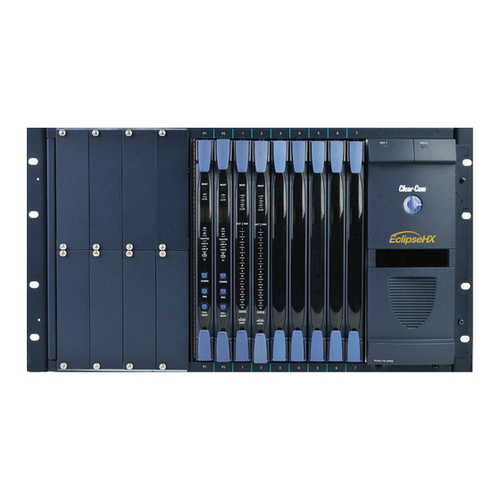
The matrix chassis is a metal rectangular box which measures six rack units (6RU) high and 19-inches wide (26.9 cm x 48.3 cm). The Eclipse HX-Median has twin power supplies, and slots for 2 CPU cards, 7 interface cards, and 8 interface modules. - Page 15 Figure 2: Eclipse HX-Median front panel Eclipse HX-Median User Guide...
- Page 16 Key: Eclipse HX-Median front panel Feature Description Interface module slots (unused in this example). The Eclipse HX-Median can house up to 8 interface modules. Blank panels can be installed to unused slots. For more information about interface modules, see 3.4 Interface modules CPU cards (P1 and P2).
- Page 17 Figure 3: Eclipse HX-Median rear panel Eclipse HX-Median User Guide...
-
Page 18: Power Supplies
3.2.2 Power supplies The Eclipse HX-Median matrix has two Euro Cassette power supply units that can be easily installed or removed as needed. One power supply unit can power an entire matrix. The second unit provides a backup in case of failure or damage to the first unit. -
Page 19: Main Features Of The Eclipse Hx-Median
3.2.3 Main features of the Eclipse HX-Median Features of the Eclipse HX-Median matrix system include: • A six rack-unit (6RU) frame. • Full audio bandwidth throughout the signal chain, producing superior broadcast audio quality. The system maintains 24-bit depth, a sampling rate of 48 kHz, and 30 Hz to 22 kHz frequency response. -
Page 20: Cpu Card
3.2.4 CPU card Two CPU cards are fitted to each Eclipse HX-Median system, in a master and slave relationship. The second CPU card provides redundancy in the case of outages or planned maintenance. The master CPU card: • Provides the serial data and Ethernet connection to the connected EHX PC. -
Page 21: E-Fib Fiber Card
3.3.1.1 Intelligent linking For intelligent linking, shielded CAT5 cable is run from a port on one Eclipse HX-Median matrix to a port on a second Eclipse HX-Median matrix to form a trunkline connection. 3.3.2... -
Page 22: Ip Interface Card
3.3.6 LMC-64 interface card The LMC-64 interface allows the Eclipse HX-Median to provide Production Maestro Pro (routing software) clients with audio level metering of partylines (conferences) and four-wire ports over an IP network. -
Page 23: Interface Modules
It may also be used with AES-3 compliant third party equipment. Note: Additional interface modules may be added to the Eclipse HX-Median, using separate interface module frames such as the IMF-3 and IMF-102. For more information, see the dedicated user guide / manual for that particular interface frame. -
Page 24: User Panels
The EHX system can be set up to run on a client/server model over a network, allowing the system administrator to control multiple matrices remotely. User panels The following Clear-Com user panels are compatible with the Eclipse HX-Median: • V-Series panels, including expansion panels. • I-Series panels, including expansion panels. -
Page 25: Installing The Eclipse Hx-Median
The Eclipse distributor is not responsible for shipping damage. 4.1.2 Unpacking the System When the Eclipse HX-Median system is received the circuit cards (CPU cards and interface cards), power supplies, and rear-connector panels are pre-installed in the matrix chassis. The customer must supply: •... - Page 26 The battery is now powered. Figure 4: CPU card with detail of CON9 jumper plugs Eclipse HX-Median CPU cards are fitted with a socketed battery, normally a Renata CR2477N with a capacity of 950mAh and a life of approximately 247 days. These socketed batteries are easily replaced and this operation does not have to be carried out by service personnel.
-
Page 27: Installing The Eclipse Hx-Median
Non Volatile Data is invalid - Please check Battery Voltage If on successive power downs of the Eclipse HX-Median frame the above state is detected, and the message appears in EHX logs, then it is advisable to check the health of the CPU card on board battery, which should be nominally at least 2.8V. -
Page 28: Installing The Power Supplies
AC mains power using the IEC power connectors on the matrix’s rear panel. A fully equipped Eclipse HX-Median matrix (2 CPU cards, 7 interface cards and 8 interface modules) requires 100 - 240 VAC at 50 - 60 Hz with a maximum dissipation of 300W. -
Page 29: Installing Cpu Cards
To insert a CPU card in the matrix: Carefully place the card in the appropriate slot. Make sure the card is aligned with the top and bottom precision guides. Eclipse HX-Median User Guide... -
Page 30: Hot Patching Cpu Cards
It is advisable to replace CPUs in maintenance down times. 4.3.2 Checking the CPU Card installation The following lights indicate that the card has been properly installed in the matrix: Eclipse HX-Median User Guide... - Page 31 Once the CPU card has initialized, you can use the Eng button to request frame information (such as the software version and the current IP address). For more information, see 5.5 CPU card lights and controls. Eclipse HX-Median User Guide...
-
Page 32: Installing Interface Cards
4.4.3 Combining interface cards in the frame The Eclipse HX-Median can allocate up to 496 audio ports in total. However, the number of ports that you actually use will depend on the combination of interface cards you fit to the frame. -
Page 33: Static Sensitivity
More ports can be utilized on the Eclipse HX-Median by using higher capacity interface cards, such as the E-MADI64 card. For example, if you installed 5 E-MADI64 cards, using 64 audio ports, you could add a further 2 MVX-A16 cards. -
Page 34: Hot Patching (Hot Plugging)
When an interface card is physically installed, its ports must be assigned functions in the EHX configuration software (see your EHX documentation). 4.4.8 Checking MVX-A16 analog port card installation The following front panel lights indicate that an analog port card has been properly installed in the matrix: Eclipse HX-Median User Guide... -
Page 35: Wiring Audio Devices To The Matrix Frame
If there is excessive noise on the lines between the device and the matrix, the device may be electronically unbalanced with the rest of the system. The device must be isolated with external isolation transformers. Eclipse HX-Median User Guide... -
Page 36: Wiring Panels To The Matrix Frame
Transmits digital data from the panel back to the matrix. Pair 3 Transmits audio from the panel to the matrix. Pair 4 Transmits digital data from the matrix back to the panel. Table 5: 4-Pair analog wiring Eclipse HX-Median User Guide... -
Page 37: Single-Pair Digital
STP cable. Pair 1 transmits and receives multiplexed digital and analog between the matrix and the panel. Ensure that the Select switch on the rear of the panel is in the correct position for the intended use. Eclipse HX-Median User Guide... -
Page 38: Wiring Cpu Card Interfaces
Note: The above wiring diagram refers to DIG-2 and is shown as an example only (DIG-2 panels are not compatible with the Eclipse HX-Median. Wiring CPU card interfaces The CPU card holds the circuitry for connecting to, and communicating with, the following interfaces: •... -
Page 39: Cpu Card Interface Connectors
4.7.1 CPU card interface connectors GPI/ RLY INTERFACE RS-232 ALARM I/O GP-OUT GP-IN LAN1 LAN2 Figure 12: CPU card interface connectors Key to CPU card interface connectors Feature Description Eclipse HX-Median User Guide... - Page 40 The General Purpose Inputs (GPI-6) Instruction Manual. RS-232 DB-9 Connector The DB-9 connector labeled RS-232 connects the Eclipse HX-Median matrix to an external computer. To connect a computer to the matrix, run cable from the RS-232 connector to the PC’s serial port. The maximum recommended length of the cable is approximately 10 feet (3 meters).
- Page 41 9. These contacts are “dry”, (no voltage is supplied to them by the matrix) and are rated at 1 A at 24 VDC. They should not be used for AC mains line current. Pins are provided for adding an additional alarm source to the matrix’s Eclipse HX-Median User Guide...
- Page 42 Pin 6 is an alarm input to the Eclipse HX-Median matrix. It is connected to the input of a 3.3 V logic device. A logic high on this input will cause the Eclipse HX-Median matrix to detect an alarm condition. A logic low or an open circuit means that the matrix will not detect an alarm condition.
- Page 43 Note: If the GP-OUT port is used on an Eclipse HX-Median matrix fitted with XP power supplies (part 740101Z) the following filter must be fitted between the PROC-RCC socket and the cable: CINCH FA-25PS/1-LF 25W D-type in-line 1000pF filter...
- Page 44 The voltage level at the external input pin should not be allowed to go below EXTVIN– or above +6 V with respect to EXTVIN–. Eclipse HX-Median User Guide Non-isolated mode To cause an input to detect an active signal in non-isolated mode, the...
- Page 45 If this port is used a ferrite core must be added to the socket end of Note: each cable. A suitable ferrite core is Würth Electronik part: 74271132. Clear-Com recommends the use of shielded cable. Table 6: Key to CPU card interface connectors DSE1/T1 Matrix to Matrix crossover cable connections Eclipse HX-Median User Guide...
-
Page 46: E1/T1 Matrix To Matrix Straight Cable Connections
Straight CAT5 cables are used to connect an E-QUE card to a FreeSpeak / CellCom / FreeSpeak II antenna or splitter. The E1 pinout for connecting an antenna or splitter is shown in Table 10: E1 pinout for connecting a FreeSpeak / CellCom / FreeSpeak II antenna or splitter. Eclipse HX-Median User Guide... - Page 47 Table 9: E1 pinout for connecting a FreeSpeak / CellCom / FreeSpeak II antenna or splitter Matrix 1 Pin Description Matrix 2 Pin Not connected Not connected Not connected Not connected Table 10: E1 to FreeSpeak / CellCom / FreeSpeak II antenna or splitter straight cable connection Eclipse HX-Median User Guide...
-
Page 48: Using The Eclipse Hx-Median
CD-ROM for later use. Note: The CPU card in the Eclipse HX-Median stores up to four complete configurations. You can apply a configuration directly from the CPU card or from the connected PC. Setting the default IP Address To reset the CPU LAN ports to their default IP addresses, press and hold the ENG and FULL RESET buttons on the CPU front card until the card resets. -
Page 49: Configuration Restrictions For Ethernet Ports
• A power failure. • The replacement of a port card. • The replacement of a panel. An Eclipse HX-Median system operates with either one or two CPU cards. Eclipse HX-Median User Guide... -
Page 50: Cpu Card Lights And Controls
If the main card is removed or becomes non-operational for any reason, the system will automatically switch to the second card as backup. CPU card lights and controls RESET +3.3V MASTER LAN A LAN B IN SYNC CONFIG RESET Figure 22: CPU card lights and controls Eclipse HX-Median User Guide... - Page 51 EQUE FPGA VERSION USUPPORTED message is displayed by the master CPU card. The dot matrix lights will also display system information when the ENG Note: button is pressed on the master CPU card. This is described below in the section on the ENG button. Eclipse HX-Median User Guide...
- Page 52 Master Light An Eclipse HX-Median system can have two CPU cards, although the system will operate with only one. If the primary card becomes unavailable for any reason, the second card can serve as backup while the primary card is repaired or replaced.
- Page 53 It is the system number of the node within the linked set (for example, SYSTEM 3). • Software version number. Version number of the config card software (for example, RACK 1.0.2.1). • Hardware serial number. For example, SERIAL 2251, in the case where the HW serial number is 2251. Eclipse HX-Median User Guide...
-
Page 54: Using The Embedded Configuration
A tool, such as a pin, is used to press and hold the RESET button. Continue holding the CONFIG, ENG and RESET buttons until the CPU card’s dot matrix display displays 0. It may take 1 - 2 seconds before 0 is displayed. Eclipse HX-Median User Guide... - Page 55 The embedded configuration has now been activated. To deactivate the embedded configuration, perform a CPU card reset. The configuration (1, 2, 3 or 4) that was previously active on the CPU card replaces the embedded configuration as the active configuration. Eclipse HX-Median User Guide...
-
Page 56: Mvx-A16 Analog Card Front-Panel Lights And Controls
MVX-A16 analog card front-panel lights and controls RESET +12V -12V +3.3V ACTIVE VOX FRAME STATUS DATA Figure 23: MVX-A16 analog card front panel lights and controls Eclipse HX-Median User Guide... - Page 57 EHX application. Each of the port card’s 16 green VOX lights corresponds to one of 16 rear- panel connectors or “ports” to which audio devices (intercom panels or interfaces) can be connected. Eclipse HX-Median User Guide...
-
Page 58: Diagnosing Power Supply Problems
Table 12: Key to MVX-A16 analog front panel lights and controls Diagnosing power supply problems The Eclipse HX-Median has two Euro Cassette power supply units. One power supply unit can power an entire matrix. The second unit provides a backup in case of an equipment failure. - Page 59 The XP type power supplies (part 740101Z) may need to be adjusted if E-QUE, E-FIB, IVC-32 or LMC-64 interface cards are installed. For more information, see the Eclipse HX Upgrade Guide. Note: Power-One power supply units (part 720379Z) should not be adjusted. Eclipse HX-Median User Guide...
-
Page 60: Conditions That Cause An Alarm
• If a new alarm condition or conditions occur before the original alarm conditions are corrected, the internal buzzer and relay contacts will not reactivate. They will only reactivate after all original alarm conditions are corrected. Eclipse HX-Median User Guide... -
Page 61: Auxiliary Alarm Lights
CPU card, not a power supply, has overheated. 5.7.4.5 PSU2 Fail When the first power supply unit is operating correctly, the PSU2 light stays off, while the four green power supply lights (+12V, +5V, +3.3V, -12V) stay on continuously. Eclipse HX-Median User Guide... -
Page 62: Power Supply Lights
For detailed information about connecting the matrix to panels, interfaces and other devices, see 4 Installing the Eclipse HX-Median. The Eclipse HX-Median matrix frame connects to devices such as the external computer that runs the EHX configuration software, panels, interfaces, and other matrices through its rear- panel hardware connectors, often called ports. -
Page 63: Connecting The Cpu Card
Note: For detailed information about connecting the matrix to panels, interfaces and other devices, see 4 Installing the Eclipse HX-Median. 5.8.3 Connecting interface cards Each rear-connector panel associated with an MVX-A16 (analog) interface card holds the sixteen RJ-45 connectors that connect the matrix to user panels, interface modules and other intercom devices. - Page 64 Each rear connector panel associated with an E-FIB interface holds two fiber ports (TXVRA and TXVRB). Note: For detailed information about connecting the matrix to user panels, interface modules and other devices, see 4 Installing the Eclipse HX-Median. Eclipse HX-Median User Guide...
-
Page 65: Madi64 Card
The standard maximum cable length is 2km, using fiber cable, or 50m using coaxial cable. Up to 15km is available to special order, using the single mode fiber option. Note: All MADI channels have standard EHX settings, including VOX and in-use tally. Eclipse HX-Median User Guide... -
Page 66: E-Madi64 Front Panel Lights And Controls
E-MADI64 front panel lights and controls RESET +3.3V LOCK VID WRD 44.1 CHANNELS ERROR ACTIVE E-MADI Figure 25: E-MADI64 front panel lights and controls Eclipse HX-Median User Guide... - Page 67 96KHz.If the quantity of channels is either 56 or 64, the sample rate is either 44.1KHz or 48KHz. The Sample rate LED on the front of the E-MADI64 will oscillate between two sample rates when the received sample rate differs from the transmitted sample rate. Eclipse HX-Median User Guide...
- Page 68 MADI input. Note: During boot up, the Active and Error LEDS flash rapidly until the boot sequence is completed. Table 14: Key to E-MADI64 lights and controls Eclipse HX-Median User Guide...
-
Page 69: E-Madi64 Rear Panel Connectors
E-MADI64 rear panel connectors E-MADI MADI MADI IN MADI OUT CLOCK Figure 26: E-MADI64 rear panel connectors Eclipse HX-Median User Guide... -
Page 70: Madi Channels
The channel modes for the E-MADI64 are 32, 56 and 64. For more information, see Table 17: E-MADI 64 channel modes. Each MADI audio channel: • Carries one (or a mixture of) any of the 512 Eclipse HX-Median backplane timeslots. • Is 24 bits in length. -
Page 71: Madi Channel Labeling
• To disable the ID and use the EHX port name. Setting up the E-MADI64 card To set up the E-MADI card: With the Eclipse HX-Median powered off, insert the E-MADI front and rear cards into the frame. Note: The number of E-MADI64 cards you can fit to the matrix frame is limited by the available port count. -
Page 72: Connecting A Word Clock Source
LEDs (1:1 at 0.5Hz) on the front of the E-MADI64 card. 6.4.3 Connecting E-MADI 64 Audio (using Coaxial or Fiber cable) When you connect the external E-MADI64 Audio (using Coaxial or Fiber cable) to the rear of theE-MADI64 card: Eclipse HX-Median User Guide... -
Page 73: Upgrading The E-Madi64 Card
The E-MADI64 card is both centrally upgradable (you can upgrade the E-MADI64 thru the matrix frame, using EHX) and locally upgradeable, using Xilinx software, a PC and a Xilinx download cable. For more information, see the Eclipse HX Upgrade Guide. Eclipse HX-Median User Guide... -
Page 74: Fib Fiber Card
If fiber interfaces are fitted to any matrix in a linked system all the linked matrices must be reset to ensure that all matrices correctly recognize the new hardware. Note: For an overview of the Eclipse HX-Median, see 3 Overview. Eclipse HX-Median User Guide... -
Page 75: E-Fib Front Panel Lights And Controls
E-FIB front panel lights and controls RESET +3.3V PROC FRONT REAR TXVRA ACT LINK ERR TXVR TXVRB ACT LINK ERR TXVR STATUS FRAME DATA Figure 27: E-FIB front panel lights and controls Eclipse HX-Median User Guide... - Page 76 ACT LED This LED is lit if the primary fiber optic circuit is active. ERR LED This LED will be illuminated if an error condition is detected on the primary fiber optic circuit. Eclipse HX-Median User Guide...
- Page 77 LED illuminates to indicate successful communication between the fiber master card and the CPU card and that the card is the currently active fiber card (with regard to fiber card set redundancy). Table 17: E-FIB front panel lights and controls Eclipse HX-Median User Guide...
-
Page 78: E-Fib Rear Panel Lights And Connectors
Normally a protective plug is fitted to the fiber connector to protect the connector from damage or the entry of foreign materials. The protective plug should only be removed in order to fit the fiber optic cable. Replace the plug when the cable is unplugged. Eclipse HX-Median User Guide... - Page 79 The fiber optic cable for the primary and secondary circuits are plugged into the appropriate ports. An example showing three systems configured with a primary and secondary ring is shown in Figure 29: Primary and redundant ring configuration. Eclipse HX-Median User Guide...
-
Page 80: Configuring A Fiber Optic Connection
In order to diagnose faults or switch between primary and secondary rings or between primary and backup fiber linking cards the system monitoring screen in EHX must be used. Note: For more information about EHX, see your EHX documentation (including EHX Help). Eclipse HX-Median User Guide... -
Page 81: Simplex Fiber Cabling
When there is no break in the fiber connections the fiber audio will be routed using the primary ring. If there is any connection failure on the primary ring and the secondary ring is intact then the fiber audio routing will move to the secondary ring. Eclipse HX-Median User Guide... -
Page 82: Dual Card Set Redundancy
This approach affords full redundancy, offering protection against component failure within a single Fiber-optic Linking Card Set. Note: In the absence of an Uninterrupted Power Supply this configuration will not protect against loss of the node or Matrix Frame itself. Eclipse HX-Median User Guide... -
Page 83: Fault Tolerance
When a ring with non-adjacent failures sub-divides into two sub-rings, audio and data from the failed nodes will not be available to the nodes in either sub-ring, audio will continue to be Eclipse HX-Median User Guide... - Page 84 5 seconds after the fault condition is cleared or repaired. An example of how a system with multiple matrices would be wired together is shown in Figure 32: Example fiber-optic connection setup Eclipse HX-Median User Guide...
- Page 85 - RX1 System #5 System #4 TX1- E-FIB TX1- E-FIB card#1 - RX1 card#1 - RX1 TX2- E-FIB TX2- E-FIB card#1 - RX2 card#1 - RX2 Primary ring Secondary ring Figure 31: Example fiber-optic connection setup Eclipse HX-Median User Guide...
-
Page 86: Que E1/T1 Card
Note: You do not require an Ethernet cable connected to the E-QUE card LAN port for the card to function correctly. For an overview of the Eclipse HX-Median matrix, see 3 Overview. Eclipse HX-Median Matrix User Guide... -
Page 87: E-Que Front Panel Lights And Controls
E-QUE front panel lights and controls RESET +3.3V STATUS LAN DATA LINK Figure 32: E-QUE front panel lights and controls Eclipse HX-Median User Guide... - Page 88 LAN DATA light illuminates to indicate there is data passing through the Ethernet port. LAN LINK light amber LAN LINK light illuminates to indicate a connection to the LAN port. Table 19: Key to E-QUE front panel lights and controls Eclipse HX-Median User Guide...
-
Page 89: E-Que Rear Panel Connectors
E-QUE rear panel connectors Ref in DECT Ref out E-QUE 1 – 4 5 – 8 Figure 33: E-QUE rear panel connectors Eclipse HX-Median User Guide... -
Page 90: E-Que Interface Card Applications
• FreeSpeak/CellCom/FreeSpeak II antennas and splitters to an Eclipse HX matrix. • Provide E1 and T1 connections to other systems. Note: For more information about E1 and T1 cable pinouts and cable connections, see: • 4.8 E1/T1 Matrix to Matrix straight cable connections. Eclipse HX-Median User Guide... -
Page 91: Freespeak/Cellcom/Freespeak Ii Application
DECT sync signal and this will not be converted by third party equipment or fiber interfaces. Three connections schemes are illustrated below. Figure 34: E-QUE card antenna connection Eclipse HX-Median User Guide... - Page 92 DECT Sync links between matrices to ensure the correct operation of the FreeSpeak/CellCom/ FreeSpeak II system. Multiple E-QUE interface cards within a single matrix do not require external DECT sync cables, connected as the signal uses the backplane. Eclipse HX-Median User Guide...
-
Page 93: E1 Trunk And Direct Modes
30 channels of G.722 or G.711 encoded audio available on each of ports 1 and 5, giving 60 channels per card. The E1 specifications are: • HDB3 Encoding. • Long Haul Receive Signal Level. • E1 120 Ohm Transmit Pulse Amplitude. Eclipse HX-Median User Guide... - Page 94 E1 Direct in EHX hardware setup. Figure 37: Matrix to Matrix direct E1 Trunking E1 trunking between matrices can also be achieved over an E1 network, as shown Figure 39: E1 Trunking with an E1 Network. Eclipse HX-Median User Guide...
- Page 95 Figure 38: E1 Trunking with an E1 Network The E-QUE interface can also be used to connect the matrix to third party equipment using E1 port 1 or 5. Figure 39: Matrix to Third Party E1 connection Eclipse HX-Median User Guide...
-
Page 96: T1 Trunking
• T1 Long Haul (LBO 0 dB) Transmit Pulse Amplitude. • Balanced. • 120 Ohm Line Impedance. • No Signaling. • G.722 or G.711 64 kbit/s Audio Encoding. • Tx Clock locally generated. • Rx Clock Line Recovered. Eclipse HX-Median User Guide... - Page 97 T1 trunking between matrices can also be achieved over an E1 network as shown in Figure 42: T1 Trunking using an E1 Network. In this case T1 ports 1 and 5 of the E-QUE rear card are connected using standard straight- through CAT5 cables rather than crossover CAT5 cables. Eclipse HX-Median User Guide...
-
Page 98: Trunking Failover
When failover occurs from primary to backup there will be a three second audio break on any route running over the trunk. If the trunk routing is later switched back from the backup trunk to the primary trunk there will be no loss of audio. Eclipse HX-Median User Guide... -
Page 99: Card For Ip-Based Connections
(not used) and a LAN port used for the IP connection. Note: An Ethernet cable must be connected to the IVC-32 interface LAN port for the card to function correctly. Note: For an overview of the Eclipse HX-Median, see 3Overview. Eclipse HX-Median User Guide... -
Page 100: Front Panel Lights And Controls
IVC-32 front panel lights and controls RESET +3.3V STATUS LAN DATA LINK Figure 42: IVC-32 front panel lights and controls Eclipse HX-Median User Guide... - Page 101 LAN DATA light illuminates to indicate there is data passing through the Ethernet port. LAN LINK light amber LAN LINK light illuminates to indicate a connection to the LAN port. Table 21: Key to IVC-32 front panel lights and controls Eclipse HX-Median User Guide...
-
Page 102: Rear Panel Connectors
IVC-32 rear panel connectors Ref in DECT Ref out IVC-32 1 – 4 5 – 8 Figure 43: IVC-32 rear panel connectors Eclipse HX-Median User Guide... -
Page 103: Interface Applications
This server will provide a link over IP between Concert users and the Eclipse matrix. Concert users cannot connect directly to the IVC-32 interface card. Concert users communicate with Eclipse users using a soft-panel, rather than the main Concert Client application. Eclipse HX-Median User Guide... - Page 104 This soft panel is configured using the EHX configuration software and the configuration information is uploaded to the Concert user’s soft-panel on connection to the matrix. Figure 44: IP communication using an IVC-32 interface card Eclipse HX-Median User Guide...
-
Page 105: Metering Card
LMC-64 metering card The Level Meter Card (LMC-64) interface card enables the Eclipse HX-Median to provide audio level metering for Production Maestro Pro over a network. Each LMC-64 interface card can meter up to 64 virtual partylines (conferences) and four- wire ports. -
Page 106: Front Panel Lights And Controls
10.1 LMC-64 front panel lights and controls RESET +3.3V STATUS LAN DATA LINK Figure 45: LMC-64 front panel lights and controls Eclipse HX-Median User Guide... - Page 107 LAN DATA light illuminates to indicate there is data passing through the Ethernet port. LAN LINK amber LAN LINK light illuminates to indicate a connection to the LAN port. Table 23: Key to LMC-64 front panel lights and controls Eclipse HX-Median User Guide...
-
Page 108: Rear Panel Connectors
10.2 LMC-64 rear panel connectors Ref in DECT Ref out LMC-64 1 – 4 5 – 8 Figure 46: LMC-64 rear panel connectors Eclipse HX-Median User Guide... -
Page 109: Interface Applications
The LMC-64 interface broadcasts audio level data to Production Maestro Pro clients over an IP network. This enables multiple Production Maestro Pro clients across a network to display any audio level that is being metered. Figure 47: Audio level metering with the LMC-64 interface Eclipse HX-Median User Guide... -
Page 110: Maintaining The Eclipse Hx-Median
Maintaining the Eclipse HX-Median The Eclipse HX-Median matrix system connects a complex network of microprocessor controlled devices. Due to the complexity of the system, field service should be limited to isolating a problem to the specific circuit board that may be causing the problem. Once the circuit board has been identified, it can be either repaired or replaced. -
Page 111: Fail-Safe Modes
• One of each type of interface in the system. 11.2 Fail-Safe modes High reliability is one of the main objectives of the Eclipse HX-Median system design. The following features of the system minimize the effects of a component failure. 11.2.1 Dual power supplies The Eclipse HX-Median matrix includes two Euro Cassette power supply units. -
Page 112: Troubleshooting
When a problem is identified in the power supplies or the circuit cards, the suspect component can be replaced with a properly functioning component to see if the problem is repaired. 11.3.1.2 Example power supply issues Problem: One or more power supply lights are unlit on one interface card Eclipse HX-Median User Guide... - Page 113 The power supply lights do not illuminate on one of the two CPU cards. When the system is functioning properly, the power-supply lights on both CPU cards illuminate. If the power-supply lights on a CPU card fail to illuminate, the problem may be Eclipse HX-Median User Guide...
-
Page 114: Troubleshooting Data Issues
CPU card’s operational memory (located in its microprocessor’s RAM), thus clearing up any corruption of data that may have occurred in the analog port interface microprocessor. The interface and all connected panels Eclipse HX-Median User Guide... - Page 115 Action 4: Replace the panel. Problem: Audio sounds low or distorted from a panel. Action 1: Check the matrix’s currently active CPU card’s power lights. If any of the lights are not lit, replace the card. Eclipse HX-Median User Guide...
-
Page 116: System Block Diagram
Action 2: Check the analog port input and output gain settings for the port in EHX. Action 3: Check the panel’s listen-level adjustment settings in EHX. 11.4 System block diagram Figure 48: System block diagram Eclipse HX-Median User Guide... -
Page 117: Specifications
Mechanical Category Measures / comments Height 10.6 inches (267 mm or 6 RU) Width 19 inches (482 mm) Depth 16 inches (410 mm) Front Card Depth 300 mm Weight 20 to 35 kg Table 26: Mechanical Eclipse HX-Median User Guide... -
Page 118: Environmental
<0.1 %, @ 0 dBu, 100 Hz to 20 kHz Off Noise <–70 dBu (20 Hz - 22kHz) On Noise <–65 dBu (20 Hz - 22 kHz) Key Response, Intra-System <40 ms for audio route Table 28: Matrix frame capabilities Eclipse HX-Median User Guide... -
Page 119: E-Madi64 Interface Front Card
-55º C to +70º C Humidity 40 - 90% non-condensing Power +3.3V Table 30: E-MADI64 interface rear card 12.7 E-MADI64 fiber cable Category Measures / comments Fiber cable Multimode 62.5/125µm Coaxial cable 75ohm Table 31: E-MADI64 fiber cable Eclipse HX-Median User Guide... -
Page 120: E-Madi64 Fiber Transceiver
Class 1 Laser Product. 12.9 E-MADI64 clock sources Clock type Clock source Word Clock 44.1KHz 48KHz 96KHz SD Video NTSC 720P60 HD Tri-Level Sync 720P59.94 720P50 720P30 720P27.97 720P25 720P24 720P23.98 1080P60 1080P59.94 1080P50 1080P30 Eclipse HX-Median User Guide... -
Page 121: Fiber Interface Front Card
12.11 Fiber interface rear card Category Measures / comments Height Depth 58mm (max) Operating Temperature 0º C to +40º C Storage Temperature -55º C to +70º C Humidity 40 - 90% non-condensing Power +3.3V Table 35: Fiber interface rear card Eclipse HX-Median User Guide... -
Page 122: Fiber Cable
-55º C to +70º C Humidity 40 - 90% non-condensing Power (combined cards) +3.3V 3.5A +5V 0.7A +12V 0.05A Table 38: E-QUE interface front card 12.15 E-QUE interface rear card Category Measures / comments Height Depth 58 mm (max) Eclipse HX-Median User Guide... -
Page 123: Interface Front Card
0º C to +40º C Storage Temperature -55º C to +70º C Humidity 40 - 90% non-condensing Table 41: IVC-32 interface rear card 12.18 LMC-64 interface front card Category Measures / comments Height Depth 300 mm Eclipse HX-Median User Guide... -
Page 124: Interface Rear Card
Audio Interface 16, bi-directional Input Format Balanced Output Format Balanced Ground Isolation None; expected at User Panel/Station Analog port card outputs Level 0 dBu nominal Impedance 100 Ohms balanced Frequency Response 30 Hz–22 kHz ± 3 dB Eclipse HX-Median User Guide... -
Page 125: Data Interface: 16 Bi-Directional
RJ-45 to Clear-Com standard pinout Transmission Distance 3000 ft. (1000 m) maximum Table 46: Data interface: 16 bi-directional 12.23 System programming Category Measures / comments Group Calls Number of Grouped Ports 4000 maximum Conferences per Matrix Eclipse HX-Median User Guide... -
Page 126: Minimum Pc Requirements (For Ehx Software)
• Microsoft Windows 8.1 (32-bit and 64-bit) • Microsoft Windows Server 2008 SP2 (32-bit and 64-bit). • Microsoft Windows Server 2008 R2 (64-bit). Operation on other platforms is no longer supported. Table 48: Minimum PC requirements Eclipse HX-Median User Guide... -
Page 127: Recommended Pc Requirements (For Ehx Software)
Positronics AC Power Input IEC (1 per PSU) Input Voltage AC 100 V to 240 V, 50/60 Hz Power Consumption 300 W Maximum Status Indicators LEDs viewable from front of rack Table 50: Power supply unit Eclipse HX-Median User Guide... - Page 128 Performance specifications included in this user guide are design-center specifications and are included for customer guidance only and to facilitate system installation. Actual operating performance may vary. Eclipse HX-Median User Guide...
-
Page 129: Glossary
The device from which audio signals are sent is called a source. Duplex All real-time communication between individuals talking face to face is full duplex, meaning that they can both talk and listen simultaneously. The Eclipse HX matrices provide full-duplex audio. Eclipse HX-Median User Guide... - Page 130 When the call is completed the destination’s audio pathways are restored to their original state before the interruption. Eclipse HX-Median User Guide...
- Page 131 2 RU is 3.5 inches (88.9 mm), 3 RU is 5.25 inches (133.35mm), and so on. Remote panel Any intelligent intercom device connected to the back-panel ports of the matrix frame. This term does not refer to devices connected through interfaces. Eclipse HX-Median User Guide...
- Page 132 The threshold level is set in the EHX configuration software. V-Series User panels used with Eclipse HX systems, providing advanced intercom facilities. Available in rack mount and desktop formats. I-Series user panels are also supported (see above). Eclipse HX-Median User Guide...
Need help?
Do you have a question about the Eclipse HX-Median and is the answer not in the manual?
Questions and answers