
Subscribe to Our Youtube Channel
Related Manuals for nvent raychem tcontrol-cont-03


Summary of Contents for nvent raychem tcontrol-cont-03
- Page 1 TCONTROL-CONT-03 COMPACT MICROPROCESSOR CONTROLLER OPERATING AND INSTALLATION MANUAL...
-
Page 3: Table Of Contents
7.3 Ramp function ............26 7.4 Limit comparators .............26 7.5 Timer ................28 7.6 Outputs ..............30 7.7 Binary functions ............32 7.8 Display/Operation/Service counter ......34 7.9 Interface ..............38 Section − 8 Supplement ............39 8.1 Technical Data ............39 8.2 Alarm and fault messages ........43 8.3 Self-optimization ............44 nVent.com | 3... -
Page 4: Introduction
CAUTION! This symbol in combination with the signal word indicates that Damage to assets or data loss will occur, if the respective protective measures are not carried out. Note symbols TIP! This symbol refers to an Important information about the product or its handling or additional use. REFERENCE! This symbol refers to Further information in other sections, chapters or manuals. 4 | nVent.com... -
Page 5: Type Designation
Type designation Type key Type description 702071/9-1131-23-00 TCONTROL-CONT-03 (nVent Part No.: nominal dimension 48 mm x 48 mm 1244-0006829) • 1 analog input • 3 relays 702071/9-1131-23-00 TCONTROL-CONT-03/MA (nVent Part No.: nominal dimension 48 mm x 48 mm 1244-0006829) • 1 analog input • 2 relays • 1 analog output (user configurable 0/4…20 mA or 0/2…10 V) 702071/9-1131-23-53 TCONTROL-CONT-03/COM (nVent Part No.:... -
Page 6: Type-Dependent Factory Settings
Scale low level (SCL) -50 Scale high level (SCH) Controller (Cntr): Controller type 1 (= 2-state ON/OFF) 4 (= continuous (CtYP) 4…20 mA) Output value at Out of Range Manual mode inhibited inhibited Self-optimization inhibited inhibited Microsoft and Windows are registered trademarks of Microsoft Corporation. 6 | nVent.com... - Page 7 (SiGn) Display/Operation/Service counter (diSP): Decimal place 1 (= one digit after 1 (= one digit after (dECP) decimal point) decimal point) Service interval 30000 0 (= switched off) (oCAL) Level inhibit Parameter and Parameter and Configuration level Configuration level nVent.com | 7...
- Page 8 Proportional band 1 Proportional band 1 Parameter set 1: (Switched off) Cycle time 1 Undocumented parameters Parameter Factory setting for type TCONTROL- CONT-03 TCONTROL- CONT-03/MA Bit parameter: Parameter 11 (enables to use for parameter “Cy” values from 1 to 9999) 8 | nVent.com...
-
Page 9: Installation
Dimensions Close mounting Minimum spacing of panel cut-outs horizontal vertical without setup plug > 8 mm > 8 mm with setup plug > 8 mm > 65 mm 44.5 +0.6 (1) Connection for PC interface adapter (setup plug) (2) Panel cut-out Installation 1. Insert the device from the front into the panel cut-out. 2. Push the fastening frame from the panel rear onto the device body and press the springs against the panel rear until the lugs engage in their slots and it is sufficiently fastened. nVent.com | 9... -
Page 10: Electrical Connection
• Do not connect any additional loads to the supply terminals of the device. DANGER! H azardous electrical voltage. I njury or death caused by electric shock. The electrical connection must only be carried out by qualified personnel. TIP! Identify the device version by way of the type key. Installation information on conductor cross sections Cable size Cross section Solid core ≤ 1.3 mm Stranded wire, with core-end ≤ 1.0 mm ferrule Plug-in terminal strips (screw terminals). 10 | nVent.com... -
Page 11: Electrical Isolation
(5.2) (5.2) Binary input 2 (for potential-free contact); (for potential-free contact); (alternative to output 3, (alternative to input configurable) 0/2—10V, configurable with setup program) Analog input (6.1) Standard signals (input (6.2) Thermocouple 0/2—10V alternative to binary input 2) (6.3) RTD temperature probe (6.4) RTD temperature probe (3 wire) (2 wire) RS485 interface (Option) Voltage supply 110—240 V AC (Option: 20—30 V AC/DC) nVent.com | 11... -
Page 12: Operation
- Limit comparators LC EXIT - Timer tFCt - Outputs OutP next/previous - Binary functions b , nF parameter - Display d , SP 1. Either the Operator (OPr) or - Interface i ntF the User level (USEr) exists 12 | nVent.com... -
Page 13: User Level Configuration
A maximum of eight frequently used parameters can be made available in the User level. Use the Setup program to configure these parameters. O nce these parameters are selected a customer friendly name can be assigned. Names can consist out of maximum four characters (represented on 7-segment display). If no name is assigned the factory defaults will be used. Figure shows the menu of the Setup program (in case of TCONTROL-CONT-03/MA and .../COMA parameter 8 is switched off) nVent.com | 13... -
Page 14: Defining Various User Levels
(top - red) Parameter flashes 1. Select parameter by pressing 2. Change to the entry mode using (lower display blinks) 3. Change a value using The value alters dynamically for as long as the key is kept pressed. 4. Take over the entry with or automatic return after 2 s or cancel the entry with the value will not be applied. TIP! I f the function key is pressed for > 2 s, the device changes back to normal display. 14 | nVent.com... -
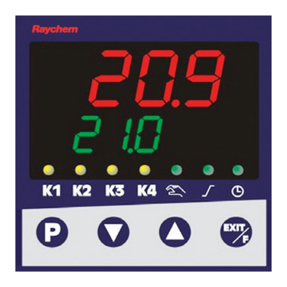
Page 15: Controller
Regulation to set point value 21,0 Further levels: USEr EXIT PArA Reduce set point value ConF alternatively Normal display I n normal display, the controller regulates to the entered set point value. Changing the set point value From the normal display: 1. Change the set point value using (the value will be automatically applied) T he longer the key is kept pressed, the faster the set point value changes. nVent.com | 15... -
Page 16: Display Of The Software Version
Navigation principle one level one level forward backward EXIT 1. Operator level (OPr) only visible if no User level (USEr) exists next/previous parameter Levels can be inhibited. Levels can be inhibited. Chapter 4.4 „Defining various user levels“ Chapter 4.4 “Defining various user levels” 16 | nVent.com... -
Page 17: Operator Level
Normal display OPr/USEr PArA Parameter level PArA >2s EXIT or timeout Navigation principle one level one level backward forward EXIT 1. Either the Operator (OPr) or the User level (USEr) exists next/previous parameter Levels can be inhibited. Chapter 4.4 “Defining various user levels” nVent.com | 17... - Page 18 HyS1 1.0… with Pb1,2 = 0. 999.9 HyS1, 2 100% 0.0… HyS2 1.0… 999.9 Valve 5…60… Used run time range of the control run time 3000s valve (actuator) of the modulating controller Operating -100… Output value for P and PD controllers value 0… (for x = w is y = Y0) +100% Output 0…100% Maximum output value limit value limits Minimum output value limit -100… (Only effective when Pb>0!) +100% 1) For 3-state controllers only (controller output 2) 18 | nVent.com...
-
Page 19: Configuration Level
P arameters are not displayed unless the equipment level permits the function assigned to the parameter. This means, for example, that interface parameters can only be configured, if the device is equipped with an interface. TIP! S ome parameters can only be programmed through the Setup program. In the following tables, these are marked in the “Parameters” column with “(Setup)”. TIP! Standard factory settings are displayed bold in the following tables in the “Value/Selection” and “Description” columns. Non-standard factory settings are shown in Chapter 1.5 “Type-dependent factory settings”. TIP! F or activation of binary input 2 the setup program is required (Hardware assistant). nVent.com | 19... - Page 20 Analog selector Some parameters in the Configuration level allow users to select from a series of analog values. The list below shows all available options. Value Description Deactivated Analog input Process value Current set point value Ramp limit value Ramp set point value (Reserved) (Reserved) Set point value 1 Set point value 2 Controller output value (-100%…+100%) Controller output 1 (0…+100%; e. g. “Heating”) Controller output 2 (0…-100%; e. g. “Cooling”) Timer run time (time unit of the timer) Residual timer run time (time unit of the timer) (Reserved) (Reserved) (Reserved) 20 | nVent.com...
-
Page 21: Analog Input
Sensor type Pt100, 3 wire SEnS Pt1000, 3 wire Pt100, 2 wire Pt1000, 2 wire KTY 2 wire (reserved) Cu-CuNi T Fe-CuNi J Cu-CuNi U Fe-CuNi L NiCr-Ni K Pt10Rh-Pt S Pt13Rh-Pt R Pt30Rh-Pt6Rh B NiCrSi-NiSi N NiCr-CuNi E W5Re_W26Re C W3Re_W25Re D W3Re_W26Re 0… 20 mA 4…20mA 0…10 V 2…10 V nVent.com | 21... - Page 22 - Low limit frequency (low-pass filter) CAUTION! Measured value offset: The controller uses the corrected value for calculation (= displayed value). This value does not comply with the value measured at the measuring point. Incorrect use can cause inadmissible control values. Only carry out a measured value offset within the admissible range. Value / Parameters Selection Description deg. Celsius Temperature unit deg. Fahrenheit Unit for temperature values Un t Correction 0… Resistance in ohms at 25 °C/77 °F for value KTY at 2000 … “KTY 2-wire” probe type 25 °C 4000 Setting in the Setup program (Setup) (-> Analog input -> Analog input 1) 22 | nVent.com...
-
Page 23: Controller
Output value, -100 … Defines the output value after switching manual mode +101 to manual mode. HAnd 101 = last output value For modulating controllers: 0 = Actuator closes 100 = Actuator opens 101 = Actuator stops Setting in the Setup program (-> Controller -> Output value, manual mode) Output value at -100 … Output value in the event of overrange or Out of Range +101 underrange. rOut 101 = last output value For modulating controllers: 0 = Actuator closes 100 = Actuator opens 101 = Actuator stops Setting in the Setup program (-> Controller -> Output value at Out of Range) nVent.com | 23... -
Page 24: Ramp Function
Setting in the Setup program (-> Controller -> Self-optimization) Self-optimization is also inhibited, if the Parameter level is inhibited. Chapter 7.7 “Binary functions” Chapter 7.8 “Display/Operation/ Service counter” Ramp function The device can be operated as a fixed value controller with and without ramp function. When the ramp function is active, a new temperature set point value is controlled along a ramp and no longer as a step. It is possible to realize an ascending or descending ramp function. The ramp limit value is defined by the set point default value. 24 | nVent.com... - Page 25 Chapter 7.7 “Binary functions” Ramp rate 0.0… Value of ramp rate 999.9 (for functions 1 to 3 only) rASL 0…9999 Range of the tolerance band (in Kelvin) Tolerance around the set point value band 0 = Tolerance band inactive toLP (for functions 1 to 3 only) For the ramp function, it is possible to enter a tolerance band around the set point value curve to monitor the process value. A tolerance band signal to be used internally or transmitted via an output is triggered when the upper or lower limit is exceeded. In the following example, the tolerance band (toLP) is 40 K. Thus a tolerance band signal is triggered when the process value exceeds the upper or lower set point value by 20 K. Further information about the use of the tolerance band signal: Chapter 7.6 “Outputs” Chapter 7.7 “Binary functions” nVent.com | 25...
-
Page 26: Limit Comparators
The way the limit comparators operate can be configured by the user (lk1 to lk8). Once an alarm limit (alarm set point) is exceeded, an alarm signal can be ouput or an internal function can be initiated. T here are 2 limit comparators available (LC1, LC2). The switching differential HySt can be user defined and will always be symmetrical in relation to the alarm set point (AL). Alarm value AL relative to the set point value w The limit comparator functions lk1 to lk6 monitor the process value x for an alarm value AL which is relative to the set point value w. This means that if the set point is changed the absolute alarm values will shift as well. HySt HySt HySt HySt HySt HySt 26 | nVent.com... - Page 27 Switching state in the event of overrange Response by Out of Range or underrange (“Out of Range”) ACrA (analog Input variable for limit comparator Limit comparator selector) (see limit comparator functions lk1... process value Process lk8: process value x) value LCPr (analog Set point value for limit comparator Limit comparator set selector) (see limit comparator functions lk1 ... point value Current lk6: set point value w) set point LCSP value nVent.com | 27...
-
Page 28: Timer
How can I see that the timer is running? The green timer LED above the clock symbol flashes while the timer time counts down, and, if a timer value is displayed on the green display, its middle decimal place (xx.xx) flashes. Timer follow-up time When the timer follow-up time t2 is activated, it starts after the timer has elapsed. The timer follow-up time can be used, e. g. to control a horn. Timer in connection with the ramp function In general, set point values can also be moved to with the ramp function. For timer functions started via the tolerance limit, only the set point value (ramp limit value) is monitored. Timer signals The additional signals “Timer running”, “Timer waiting” and “Timer completed” can be used for binary outputs. 28 | nVent.com... - Page 29 Manual start by using the function key or Start condition Strt the binary signal (no restart or continuation after power supply interruption) Manual start with automatic start or restart after power ON Manual start and continuation after power supply interruption (residual running time is saved every minute) mm.ss Time unit Unit hh.mm hhh.h inverted Timer signal not inverted 00.00. The started timer runs for this time in the Set time t1 99.99 specified time unit. (Timer time) nVent.com | 29...
-
Page 30: Outputs
The set timer time only elapses when the process value has reached the tolerance toLt band. 0 = Start without tolerance band The tolerance band (in Kelvin) is symmetrical in relation to the SP set point value. toLt (1) = Start via function key, binary input or when power ON Outputs The configuration of the device outputs is subdivided in binary outputs (OutL) and analog outputs (OutA). Binary outputs are relays and logic outputs. The switching states of the binary outputs 1 to 4 are shown in the display (K1 to K4). Binary outputs Output 1 (Out1) = Relay Output 2 (Out2) = Relay Output 3 (Out3) = Logic output Output 4 (Out4) = Relay (option) 30 | nVent.com... - Page 31 FnCt Controller output 1 0... 10 V Type of signal 2... 10 V 0... 20 mA 4... 20 mA Physical output signal 0 … 101 Signal (in percent) at overrange or Value at Out of Range underrange 101=last output signal r0ut nVent.com | 31...
-
Page 32: Binary Functions
Zero point = 0 / End value = -100 Example (function as a transducer): The analog output (0...20 mA) is to be used to put out the process value (value range: 150...500 °C), this means: 150…500°C = 0…20 mA Zero point: 150 / End value: 500 Binary functions In terms of this manual a function initiated by a binary signal is called “binary function”. Several binary functions can be realized by using the signals of binary input, limit comparators, timer and ramp function. Switching behavior The following binary functions react to switch-on edges: • Start, abort self-optimization • Start, abort, start/abort timer All remaining binary functions react to switch-on or switch-off states. Power free contact or switching pulse 0 = Contact open (1) = Switch-on edge 1 = Contact closed 32 | nVent.com... - Page 33 Tolerance band signal, ramp (reserved) (reserved) toLS (reserved) Key inhibit Level inhibit: The parameter and the configuration level are inhibited. Start of self-optimization is inhibited. Display off with key inhibit (reserved) Timer acknowledgement Starting the timer Timer abort Timer stop Timer start/abort For activation of binary input 2 the setup program is required (Hardware assistant). nVent.com | 33...
-
Page 34: Display/Operation/Service Counter
Decimal place one digit after the decimal point dECP two digits after the decimal point If the value to be displayed cannot be shown including the programmed decimal point, the number of digits after the decimal point are automatically reduced. If subsequently the measured value contains less digits, the reading appears with the decimal point as programmed. 34 | nVent.com... - Page 35 Stop timer/continue timer run Timer start/abort Display timer value (manual) None Access to the individual levels can be Level inhibit (Setup) ConF inhibited. PArA and Setting in the Setup program ConF (-> Display/Operation/Service counter OPr, PArA -> Operation): and ConF - None - Configuration level (ConF) - Parameter (PArA) and configuration level - Operator (OPr), parameter and configuration level The setting is independent of binary function “Level inhibit”. When inhibiting the Parameter level, the self-optimization start is simultaneously inhibited. nVent.com | 35...
- Page 36 0. - S imultaneously press the + keys: The complete counter value is displayed on both displays for approx. 3 s. Example: Counter value 1234567; upper display = 1234, lower display = 567 Setting in the Setup program (-> Display/Operation /Service counter -> Service counter) Monitoring Selection of the interval type Service type (Setup) number Setting in the Setup program (-> Display/ Operation/Service counter -> Service counter): - Monitoring number (quantity) - Monitoring time (h) - Monitoring time (d) 36 | nVent.com...
- Page 37 - Ramp end - Service alarm - Key actuation - Manual mode User level A maximum of eight parameters from (Setup) the various levels can be defined to be available in the User level of the device. The parameter name (max. 4 characters which can be displayed with 7-segment display) can be user-defined. Without a user-default entry, the name programmed in the device will appear. Setting in the Setup program (-> Display/Operation/Service counter -> User level) nVent.com | 37...
-
Page 38: Interface
Time period in milli-seconds that elapses Min. response time 500 ms between the request of a device in the data (Setup) network and the response of the controller. Setting in the Setup program (-> Interface) TIP! W hen the communication takes place via the setup interface, the RS485 interface is inactive. TIP! F or further information a separate interface description Modbus is available (as a PDF file). 38 | nVent.com... -
Page 39: Supplement
60584 0… +1768 °C ≤ 0.25% 100 ppm/ K Pt13Rh-Pt “R” 60584 0… +1768 °C ≤ 0.25% 100 ppm/ K Pt30Rh-Pt6Rh “B” 60584 0… +1820 °C ≤ 0.25% 100 ppm/ K W5Re-W26Re “C” 0… +2320 °C ≤ 0.25% 100 ppm/ K W3Re-W25Re “D” 0… +2495 °C ≤ 0.25% 100 ppm/ K W3Re-W26Re 0… +2400 °C ≤ 0.25% 100 ppm/ K Cold junction: Pt100 internal The specifications refer to an ambient temperature of 20 °C. I ncl. measuring accuracy at the cold junction. The accuracy values refer to the maximum measuring range. Small measuring ranges lead to reduced linearisation accuracy. In the range of 300 ... 1820 °C nVent.com | 39... - Page 40 ≤ 0.25% Sensor lead resistance: max. 30 Ω per lead with three wire circuit Measuring current: approx. 250 µA Lead compensation: Not required for three wire circuit. For a 2-wire circuit, the lead resistance can be compensated by correcting the actual value. T he accuracy values refer to the maximum measuring range. Small measuring ranges lead to reduced linearisation accuracy. Standard signals input Measuring Measuring range accuracy Ambient temperature coefficient Voltage 0(2)—10 V ≤ 0.1% 100 ppm/K Input resistance R > 100 kΩ Current 0(4)— ≤ 0.1% 100 ppm/ K 20 mA Voltage drop ≤ 2.2 V T he accuracy values refer to the maximum measuring range. Small measuring ranges lead to reduced linearisation accuracy. 40 | nVent.com...
- Page 41 Contact rating 150,000 operations at rated load Contact life 350,000 operations at 1 A 310,000 operations at 1 A and cos φ > 0.7 Logic output 0/14 V / 20 mA max. Voltage (option) Output signals 0—10 V / 2—10 V Load resistance ≥ 500 Ω Load Accuracy ≤ 0.5% Current (option) Output signals 0—20 mA / 4—20 mA Load resistance ≥ 500 Ω Load Accuracy ≤ 0.5% nVent.com | 41...
- Page 42 Installation information on conductor cross sections Solid core ≤ 1.3 mm Stranded, with ≤ 1.0 mm² core-end ferrule Electromagnetic EN 61326-1 compatibility Interference emission Class B Interference immunity Industrial requirements Case Case type Plastic case for panel mounting acc. to IEC 61554 Installation depth 90.5 mm Ambient/storage –5…+55 °C / -40…+70 °C temperature range Ambient conditions rel. humidity < 90% annual average, no condensation 42 | nVent.com...
-
Page 43: Alarm And Fault Messages
Check that the connected probe complies with the configured probe type All displays ON; Watchdog or power Replace controller, lower ON trigger initialisation if initialisation takes 7-segment display (reset). longer than 5 s. flashes Overrange/underrange covers the following events: • Probe break/short-circuit • Measured value outside the probe measuring range • Display overflow nVent.com | 43... -
Page 44: Self-Optimization
T = Start of self-optimization (SO) Prerequisites The following prerequisites must be fulfilled to be able to start self- optimization: • No active level inhibit via binary functions (binF) • No active inhibit of Parameter level via Setup program (Display/ Operation/Service counter -> Operation -> Level inhibit) • Ensure that the + keys are not pressed asynchronously. Simultaneous actuation must be synchronous. Furthermore, the following five points should be taken into consideration, checked and, if necessary, adjusted, prior to starting self-optimization: • Is the suitable controller type configured? • Check and/or adjust the control action of the controller • Is it possible to sufficiently influence the process value in manual mode? • Prior to starting optimization on PID structure, ensure that the reset time (rt) is not set to 0. 44 | nVent.com... - Page 45 Zero point (0Pnt) = 0 End value (End) = 100 • For modulating controllers only: Determine the actuator time (tt) and set in the Parameter level Start of self-optimization 1. Simultaneously press the + keys (> 2 s) In the lower display, “tUnE” appears flashing. Self-optimization is completed when the display automatically changes to the standard display. The duration of self-optimization depends on the process. Canceling self-optimization 1. Cancel using + (simultaneously) nVent.com | 45...
- Page 46 46 | nVent.com...
- Page 47 | 47...
- Page 48 Fax +7 495 926 18 86 saleskz@nvent.com nVent.com ©2018 nVent. All nVent marks and logos are owned or licensed by nVent Services GmbH or its affiliates. All other trademarks are the property of their respective owners. nVent reserves the right to change specifications without notice.
Need help?
Do you have a question about the raychem tcontrol-cont-03 and is the answer not in the manual?
Questions and answers