Table of Contents
Advertisement
Quick Links
T2000 HEAT TRACE
CONTROLLER
Installation, Operating, and Maintenance manual
CM 2000
Control Module,
CM 2000+
Control Module,
AC 2000
Alarm/Communications Interface
AC 2000+
Alarm/Communications Interface, Firmware versions up
to V1.4X
0
0 0
T 2
E
U L
O D
L M
R O
N T
0
C O
0 0
T 2
˚ F
E
U L
O D
L M
R O
N T
C O
0
0 0
T 2
T
˚ F
T P
S E
T
E N
R R
E
C U
U L
O D
M P
L M
T E
R O
N T
C O
0
0 0
T 2
˚ F
T P
T
U T
S E
T P
N S
T
O U
E N
R R
T IO
C U
M
IC A
A R
A L
U N
M P
T E
I T
M M
C E
S M
C O
F A
A N
M /
E R
IN T
T R
A R
I V E
A L
T P
T
U T
C E
S E
T P
R E
T
O U
E N
R R
C U
M
S
A R
E S
A L
D R
M P
T E
I T
A D
5 8
S M
A N
1 1 7
T R
I V E
I V E
U T
C E
C E
R E
T P
R E
I E R
O U
R R
M
S
A R
E S
C A
I T
A L
S M
D R
I T
A D
5 8
0
A N
D
S M
2 0 0
E N
T R
O S
A N
1 1 7
C M
T R
Q T
I V E
R E
C E
R E
S
M
E S
A R
D R
A L
A D
5 8
0
2 0 0
1 1 7
C M
0
2 0 0
C M
0
2 0 0
C M
Firmware versions up to V2.35
Firmware versions up to V3.1X
0
0 0
T 2
E
U L
O D
L M
R O
N T
C O
0
0 0
T 2
E
U L
O D
L M
R O
N T
0
C O
0 0
T 2
E
U L
O D
L M
R O
N T
0
C O
0 0
T 2
U L
E
O D
L M
R O
N T
C O
˚ F
T
T P
S E
T
E N
R R
C U
M P
T E
U T
T P
O U
M
A R
A L
I T
S M
A N
T R
I V E
C E
R E
S
E S
D R
A D
5 8
1 1 7
0
2 0 0
C M
0
0 0
T 2
E
U L
O D
L M
R O
N T
0
C O
0 0
T 2
E
U L
O D
L M
R O
N T
C O
Advertisement
Table of Contents

Related Manuals for nvent RAYCHEM T2000


Summary of Contents for nvent RAYCHEM T2000
- Page 1 T2000 HEAT TRACE CONTROLLER Installation, Operating, and Maintenance manual CM 2000 Control Module, Firmware versions up to V2.35 CM 2000+ Control Module, Firmware versions up to V3.1X AC 2000 Alarm/Communications Interface AC 2000+ Alarm/Communications Interface, Firmware versions up to V1.4X ˚...
-
Page 2: Table Of Contents
Conducted and Radiated Emissions—FCC/DOC Statement of Compliance Technical Support Important Warnings and Notes Section 1 Overview 1.1 Introduction 1.2 nVent RAYCHEM T2000 Components 1.3 External Programming Devices 1.4 Control Module Overview 1.5 AC 2000+ Card Overview 1.6 Component Ordering Guide Section 2 Installation and Wiring 2.1 Introduction... - Page 3 8.1 Operator Maintenance 8.2 Replaceable Parts Appendix A Specifications Appendix B RAYCHEM T2000 HTC Component Wiring Diagrams B.1 Control Module / CT 2000 Contactor Wiring Diagram B.2 Control Module / CT 2000-HAZ Single Pole SSR Wiring Diagram B.3 Control Module / CT 2000-HAZ Two Pole SSR Wiring Diagram B.4 AC 2000 Alarm / Communications Interface Card Wiring Diagram...
-
Page 4: Introduction
Orient the equipment so that moisture does not enter the enclosure via the electrical connection. • The unit must not be altered or modified after shipment. Consult nVent if modification is necessary. • Periodic testing is necessary for critical applications where damage to unit could endanger property or personnel. -
Page 5: Technical Support
Go, choose an application, enter your postal code if prompted, and click Find. Contact information for your local representative will appear. FAQ – For Frequently Asked Questions, go to nVent.com, click Heating > Technical Support, and select FAQ. -
Page 6: Section 1 Overview
RAYCHEM T2000 Series Heat Tracing Controller (HTC). A RAYCHEM T2000 HTC is made up of at least one card rack, one alarm/ communications interface card, and one or more control modules, each with its own current transformer and switching module. - Page 7 1.2.5 CR 2000 CARD RACK The CR 2000 card rack was the original card rack designed for use with the RAYCHEM T2000 system. It provided each control module its own isolated power supply connection. Two versions of this card rack have been manufactured. The first version did not support the ATC (Ambient Temperature Control) signal connection between the ten control modules, and the second (Rev A) version did support the ATC signal.
-
Page 8: External Programming Devices
The type of device depends on the type of alarm/ communications interface card being used by the RAYCHEM T2000 HTC. The following sections give details on the programming devices that may be used with each type of alarm/ communications interface card. -
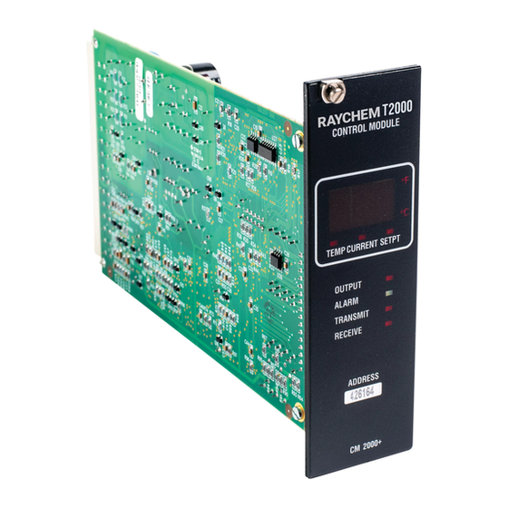
Page 9: Control Module Overview
1.4 CONTROL MODULE OVERVIEW 1.4.1 DESCRIPTION The CM 2000 and the CM 2000+ control modules, used in the RAYCHEM T2000 HTC each control, monitor, and communicate alarms and data for a single heating circuit. As single point controllers, they offer a complete range of features as well as superior reliability. The ability to install the units in Class 1, Division 2 hazardous areas supports direct field installation if desired. - Page 10 CSA (C/US) & FM Approved The RAYCHEM T2000 system is approved and certified for use in Class 1, Division 2, Groups A,B,C,D hazardous locations, making them ideal for direct installation in the field. This can save the expense of wiring back to a centrally located electrical distribution center.
-
Page 11: Ac 2000+ Card Overview
CR 2000/CR 2000+ card rack(s). IMPORTANT: The AC 2000+ belongs to a family of Group Communications Controller (GCC) devices. While specific to the RAYCHEM T2000 series of products, the AC 2000+ is nonetheless a Group Communications Controller (GCC). This nomenclature will be used through this user manual. -
Page 12: Component Ordering Guide
Controller Con-figuration Utility” program. 1.5.4 SUPPORT Application assistance is available from nVent for questions specific to the operation of the AC 2000+ hardware and software or its use in conjunction with the CM 2000 and the CM 2000+ control modules. - Page 13 The following tables summarize model codes for the RAYCHEM T2000 series products. Note that the first table identifies the most recent products. These components should be specified for new designs. Current Product Model Codes Model Code Model Description Detailed Description...
- Page 14 Panel mount rack provides a mechanical Common Power protec-tion and electrical connections for the Supply CM 2000/CM 2000+ control modules and the AC 2000 module. All control modules are individually powered. Use a CR 2000-CPS+ for new designs. 14 | nVent.com...
-
Page 15: Section 2 Installation And Wiring
2.1 INTRODUCTION This section includes information regarding the initial inspection, preparation for use, and wiring instructions for the components of the RAYCHEM T2000 HTC. See Appendix B for wiring details. 2.2 INITIAL INSPECTION Inspect the shipping container for damage. If the shipping container or cushioning material is damaged, it should be kept until the contents of the shipment have been verified for completeness and the equipment has been checked mechanically and electrically. - Page 16 PC board. Store immediately in the anti-static bag provided. Install in the reverse order. IMPORTANT: • When using an AC 2000 with a CR 2000+ or a CR 2000-CPS+ card rack, the dry contact alarm relay connections are not available. 16 | nVent.com...
-
Page 17: Wiring
A ground terminal is provided on each card rack for connection of a system ground lead. Proper system grounding is required for safe and correct operation of the RAYCHEM T2000 HTC protection features. Refer to Article 501-4(b) of the National Electrical Code for grounding in hazardous areas, if appropriate. -
Page 18: Initial Power Up
WARNING: Before applying power to the RAYCHEM T2000 HTC: • Close the panel door or stand clear of the RAYCHEM T2000 HTC. Although the control modules incorporate overcurrent protection, a destructive switch failure can result from a short circuited output. To avoid the possibility of any injury, no one should be directly in front of the switches when they are initially powered up. -
Page 19: Section 3 Control Module Programming And Configuration
The control module then turns on all LEDs (except TRANSMIT and RECEIVE LEDs for the CM 2000) and sequences through a test pattern so that the operator can verify that all LEDs and display segments are functioning. nVent.com | 19... - Page 20 The RECEIVE status LED is located below the TRANSMIT status LED on the right side of the control module’s front panel display. This LED will flash whenever the control module receives information over its communication port from either the AC 2000 or the AC 2000+ alarm/ communications interface card. 20 | nVent.com...
-
Page 21: Displayed Alarm Indicators
These alarm conditions may indicate that the RAYCHEM T2000 HTC or the heating load require immediate attention. This section describes in detail the various types of alarm indications that the control module may display. - Page 22 When a control module (with firmware version V2.35 or higher) is configured as an ATC SLAVE, the TS 1 FAILURE ALARM is disabled, and there is no RTD connected to the TS 1 input, then the display will appear as follows: 22 | nVent.com...
- Page 23 Always Displayed If Control TS Failure Else Displayed In Place of Control Temperature 3.3.13 FACTORY PARAMETERS UNLOCKED (CM 2000+ ONLY) If the factory parameters of a CM 2000+ control module become unlocked then the display will appear as follows: Flashing Always Displayed nVent.com | 23...
-
Page 24: Point Setup Parameters
CM 2000 control module: proportional, proportional ambient SSR (CM 2000+ only), proportional ambient contactor (CM 2000+ only) and deadband. See Section 5.2 of this manual for a complete explanation of these controlling techniques as they are implemented in the control module. 24 | nVent.com... - Page 25 • See Section 5.2 of this manual for an explanation of how the three proportional modes use the PROPORTIONAL BAND setting. • For the CM 2000 control modules (V2.35 and lower), the PROPORTIONAL BAND is fixed at 2°F (1°C), and centered around the CONTROL SETPOINT temperature. nVent.com | 25...
- Page 26 (I2t) and adjusts the output duty cycle accordingly, limiting the amount of current to an acceptable level. Range: 0.3 to 60.0 A for CM 2000+ 0.3 to 120% of SWITCH CURRENT RATING for CM 2000 26 | nVent.com...
- Page 27 If the remaining “good” sensor fails, the control module will turn the heater off. The three-character display will always flash “tSF” and the appropriate TS 1 or TS 2 FAILURE ALARM will be also be generated as well as the Control TS FailURE ALARM (assuming these alarms are enabled). Procedure: Select the temperature sensor control mode that best suits the application. nVent.com | 27...
- Page 28 VOLTAGE TURNS RATIO Setting: 4.00 To 1 IMPORTANT: When the VOLTAGE TURNS RATIO has been set appropriately, the control module will calculate the heating circuit power using the adjusted current and voltage readings. Voltage alarms also use the adjusted voltage reading. 28 | nVent.com...
- Page 29 AUTO-CYCLE INTERVAL otherwise autocycling could affect the duty-cycle. • For the earliest possible alarming of heating circuit problems, the AUTO-CYCLE INTERVAL should be set to a small value. • This feature is only available if AUTO-CYCLE is enabled. nVent.com | 29...
- Page 30 • The ATC output signal is not affected for a control module configured as an ATC MASTER in fail safe operation. • The FAIL SAFE MODE parameter should always be disabled for a control module configured as an ATC SLAVE. 30 | nVent.com...
- Page 31 NO (Steady). If set to YES (Flash) there is the possibility that the ALARM LED and the dry contact alarm output relay on the AC 2000 alarm/communications interface card may not activate if more than one control module has an active alarm. nVent.com | 31...
-
Page 32: Alarm Settings
Procedure: Adjust the HIGH TS 1 TEMP ALARM temperature setpoint to the desired value. Note that the HIGH TS 1 TEMP ALARM must be enabled in order to adjust the HIGH TS 1 TEMP ALARM temperature setpoint. 32 | nVent.com... - Page 33 A high temperature condition resulting from a forced on failure of the heating circuit should first be alarmed by the SWITCH FAILURE ALARM (see Section 3.5.16 for more information). nVent.com | 33...
- Page 34 Purpose: Alarms current levels, which are higher than a preset limit for the application. Alarm Mask: ENABLE or DISABLE Range: 0.3 to 60.0 A for CM 2000+ 0.3 to 120% of SWITCH CURRENT RATING for CM 2000 (CURRENT TURNS RATIO = 1.00) 34 | nVent.com...
- Page 35 Alarm Mask: ENABLE or DISABLE Range: 20 to 100 mA Procedure: Adjust the HIGH GFI ALARM level to the desired value. Note that the HIGH GFI ALARM must be enabled in order to adjust the HIGH GFI ALARM level. nVent.com | 35...
- Page 36 SWITCH CURRENT RATING. If the control module is unable to start the cable, it will eventually trip its output switch off and will not retry or pulse its output switch again. At this point the 36 | nVent.com...
- Page 37 These currents may exceed the overcurrent trip limit and the control module will not be able to soft start the heating circuit. If this condition persists please contact your nearest nVent sales office for recommendations and solutions to this problem.
- Page 38 SWITCH CURRENT RATNG setting. IMPORTANT: • This is a non-latching alarm. • This alarm should normally be left enabled. Currents in this range cannot be considered normal and should be investigated. 38 | nVent.com...
- Page 39 “Err” when this alarm is active. Alarm Mask: ENABLE or DISABLE Procedure: Enable or disable alarming of a non-volatile memory failure as desired. IMPORTANT: • The EEROM DATA FAILURE ALARM should always be enabled. • This alarm cannot be reset. nVent.com | 39...
-
Page 40: Section 4 Control Module Monitored Parameter Details
Purpose: The voltage reading indicates the average heating circuit voltage being measured by the control module. IMPORTANT: The control module calculates this parameter using the voltage powering the control module multiplied by the VOLTAGE TURNS RATIO to yield an adjusted voltage value. 40 | nVent.com... -
Page 41: Maintenance Data
IMPORTANT: The POWER ACCUMULATOR value will roll over to zero when the upper limit of the POWER ACCUMULATOR has been exceeded. This upper limit for the CM 2000+ is 214,748,364.7 kW-hours and the upper limit for the CM 2000 is 429,496,729.5 kW-hours. nVent.com | 41... - Page 42 Procedure: The TIME SINCE LAST RESET hours accumulator can only be reset by cycling the control module’s power. IMPORTANT: The TIME SINCE LAST RESET hours will roll over to zero when the upper limit of 65,535 hours has been exceeded. 42 | nVent.com...
-
Page 43: Section 5 Control Module Control Modes
• If the temperature sensed by the control sensor is equal to or greater than the CONTROL SETPOINT temperature + the PROPORTIONAL BAND setting, then the control module output will have a duty cycle of 0% -- the output will be off. nVent.com | 43... - Page 44 0% - 100% band. Proportional Ambient SSR Control Temperature Band For CM 2000+ Control Modules Control Sensor Temperature Duty Cycle Š Setpoint = Setpoint-proportional band/2 £ Setpoint-proportional band 100% 44 | nVent.com...
-
Page 45: Load Shedding Control Mode
If a load shedding command is received, the control module will continue to hold its output off, until one of the following four conditions occurs: 1. The GCC contact input that initiated load shedding deactivates and the GCC issues a load shedding command that will terminate load shedding mode. nVent.com | 45... -
Page 46: Ambient Temperature Control (Atc) Mode
3.4.12. For more information regarding a control module configured as an ATC SLAVE see Section 3.4.11. The two RTD inputs and the corresponding TS alarm settings of an ATC SLAVE are available for monitoring applications and are not used in controlling the output. 46 | nVent.com... -
Page 47: Section 6 Control Module Troubleshooting
IMPORTANT: If the control module does not operate properly and is being returned to nVent for service, information must be provided as to why the unit was removed from service. Contact nVent for a Return Authorization form and number prior to returning any units for repair. Upon receipt of the control module, or to check the control module for an indication of normal operation, follow the operational procedures shown below. These procedures are... - Page 48 Electrical Code requirements for your particular installation. • Terminal connections that are not tight can add resistance to an RTD circuit. Check the tightness of all screw terminal connections at time of installation and during subsequent maintenance checks. 48 | nVent.com...
- Page 49 IMPORTANT: The control module monitors the integrity of the ground fault (GF) detection transformer and associated wiring. If a fault is detected, the control module will report a GF value of 300 mA. nVent.com | 49...
-
Page 50: Common Alarms-What To Look For
• Moisture in junction box activated to indicate a ground fault condition. • Poor splice or termination • Moisture provides conductive ground path which allows ground fault current 50 | nVent.com... - Page 51 MAXIMUM POWER setting. • Damaged or partially shorted heating cable • “As built” cable length is greater than design value • Incorrect CURRENT TURNS RATIO setting • Incorrect VOLTAGE TURNS RATIO setting • Power Surge • Incorrect wiring nVent.com | 51...
- Page 52 This memory and has loaded factory defaults into this failed area. indicates an internal problem and the control IMPORTANT: This alarm cannot be reset. module should be replaced and returned to the factory for repair. 52 | nVent.com...
-
Page 53: Section 7 Ac 2000+ Programming And Configuration
7.2 INITIAL CONFIGURATION Before the AC 2000+ alarm/communications interface card can be used to interface an external programming device with RAYCHEM T2000 HTC control modules, the AC 2000+ communication ports must be configured. This is accomplished by connecting a Personal Computer (PC) to the local front panel RS-232 port using a standard serial communications cable and running the “Communication Controller Configuration Utility”... -
Page 54: Input/Output Ports
– Red or Off: The AC 2000+ is in Run Mode but an internal failure has occurred. The AC 2000+ should be returned to nVent for service. 7.2.1 DIP SWITCH SETTINGS There are six dip switches located along the top edge of the AC 2000+ (see Figure 7-1). - Page 55 The AC 2000+ is equipped with three communication ports to interface with external programming devices supporting the ModBus protocol (such as a PC, PLC or DCS). All RAYCHEM T2000 HTC parameters and data may be accessed through any of these three communication ports, using either Page or Linear Modbus Mapping.
-
Page 56: Operational Configuration
7.4 OPERATIONAL CONFIGURATION IMPORTANT: Before the AC 2000+ alarm/communications interface card can be used to interface an external upstream programming device with RAYCHEM T2000 HTC control modules, the AC 2000+ communication ports must be configured as described in Section 7.2. - Page 57 IMPORTANT: Even though the list of installed control modules will be empty, control module configuration data will not be affected as a result of this alarm, as it is stored in the control module’s own non-volatile memory. nVent.com | 57...
-
Page 58: Remote Data Access
If there is an error, an alarm will be generated describing the problem. See Section 4 of this manual for details on the control module’s measured and calculated parameters. 58 | nVent.com... -
Page 59: Ac 2000+ Alarms - What To Look For
• The external upstream device wants a particular zone to be Zone Alarms activated by receiving a remote contact input put into load shedding mode. status message from an external upstream device, their corresponding load shedding alarm is latched. nVent.com | 59... -
Page 60: Section 8 Maintenance
(if installed) may need periodic replacement. WARNING: Make sure that the power to the RAYCHEM T2000 HTC is OFF when replacing any pilot lamps! Also, be certain the power is OFF to the RAYCHEM T2000 HTC before attempting to test or service the heat tracing. -
Page 61: Appendix A Specifications
APPENDIX A SPECIFICATIONS A1 – RAYCHEM T2000 HTC Specifications Storage ambient –40°F to 185°F (–40°C to 85°C) Approvals CSA C/US Certified & FM Approved Classification • Using CT 2000-HAZ : Class I, Division 2, Groups A,B,C,D • Using CT 2000 : Ordinary Locations A2 –... - Page 62 • Modbus RTU/ASCII protocols, selectable paged (GCC/780 compatible or linear mapping • “Receive” and “Transmit” status LEDs Local Port: RS-232C mode • DE9S connector, DCE pinout • 300 to 9600 baud • Modbus RTU/ASCII protocols, selectable paged (GCC/780 compatible) or linear mapping 62 | nVent.com...
- Page 63 It is strongly recommended that you use an isolated-type interface to protect the computer from any voltage transients that may be introduced into the field wiring. nVent.com | 63...
-
Page 64: Appendix B Raychem T2000 Htc Component Wiring Diagrams
APPENDIX B RAYCHEM T2000 HTC COMPONENT WIRING DIAGRAMS B.1 CONTROL MODULE / CT 2000 CONTACTOR WIRING DIAGRAM TRACING 120 - 240 VAC 50/60Hz LINE IN CONTACTOR CONTROL + CONTROL + T2000 CT 2000 CONTROL - CONTROL MODULE CONTROL - CT MODULE... -
Page 65: Control Module / Ct 2000-Haz Single Pole Ssr Wiring Diagram
RTD SHIELD OUTPUT ALARM RTD1 SOURCE TRANSMIT RECEIVE RTD1 SENSE RTD1 COMMON ADDRESS RTD2 SOURCE RTD2 SENSE CM 2000+ RTD2 COMMON RTD1 100 Ohm Platinum DIN 43760 RTD1 D794-012 100 Ohm FROM Platinum DISTRIBUTION PANEL DIN 43760 nVent.com | 65... -
Page 66: Control Module / Ct 2000-Haz Two Pole Ssr Wiring Diagram
RTD SHIELD OUTPUT ALARM RTD1 SOURCE TRANSMIT RECEIVE RTD1 SENSE RTD1 COMMON ADDRESS RTD2 SOURCE RTD2 SENSE CM 2000+ RTD2 COMMON RTD1 100 Ohm Platinum DIN 43760 D794-013 RTD1 100 Ohm FROM Platinum DISTRIBUTION PANEL DIN 43760 66 | nVent.com... -
Page 67: Ac 2000 Alarm / Communications Interface Card Wiring Diagram
B.4 AC 2000 ALARM / COMMUNICATIONS INTERFACE CARD WIRING DIAGRAM nVent.com | 67... -
Page 68: B.5 Ac 2000+ Alarm Communications Interface Card Wiring Diagram
RTS/DCD - RESISTOR RTS/DCD - REMOTE + REMOTE + 120 ohm REMOTE - RESISTOR REMOTE - LOCAL + LOCAL + 120 ohm LOCAL - RESISTOR LOCAL - SHIELD SHIELD TO TERMINALS 9-14 OF THE NEXT CARD RACK D794-005 68 | nVent.com... -
Page 69: Ac 2000+ Local Port Rs-232 Connections
ALARM/WARNINGS RELAY DRIVER +12 100mA MAX. T2000 ALARM / COMMUNICATIONS ALARM RELAY CONTROLLER STATUS ALARM N.C. ALARMS WARNINGS RELAY COM. WARNING N.C. REMOTE LOCAL WARNING RELAY LOCAL PORT RS232 AC 2000+ 10 BASE-T ETHERNET D794-007 REMOTE PORT nVent.com | 69... -
Page 70: Cr 2000 Card Rack Terminal Assignments
B.8 CR 2000 CARD RACK TERMINAL ASSIGNMENTS D793-004 70 | nVent.com... -
Page 71: Cr 2000 Rev. A Card Rack Terminal Assignments
B.9 CR 2000 REV. A CARD RACK TERMINAL ASSIGNMENTS D793-001 D793-002 nVent.com | 71... -
Page 72: Cr 2000+ Card Rack Terminal Assignments
B.10 CR 2000+ CARD RACK TERMINAL ASSIGNMENTS D794-001 D794-002 72 | nVent.com... -
Page 73: Appendix C Label Details
Load Current or Setpoint Temp. Setpoint being displayed Actual Temp. being displayed TEMP CURRENT SETPT Output On Load Current Active Alarm OUTPUT being displayed ALARM Transmitting Information TRANSMIT RECEIVE Receiving Information ADDRESS Heat Trace Module Identification number CM 2000+ D794-009 nVent.com | 73... -
Page 74: Appendix D Card Rack Dimensions
APPENDIX D CARD RACK DIMENSIONS Cutout Dimensions: 5.33” X 18.23” Mounting: Use (4) clips provided with the Card Rack. 74 | nVent.com... -
Page 75: Appendix E Load Shedding Operations
1. When Load Shedding is enabled, the AC 2000+ broadcasts the Load Shedding status once every minute. This ensures that control modules that have temporarily lost communications or power are able to respond to the status once communications or power is restored. nVent.com | 75... -
Page 76: Control Module Load Shedding Sequence
Load Shedding command. 4. Only if the Low Temperature Alarm is ENABLED. 5. The display on CM 2000/CM 2000+ control modules will flash “Prl” (priority) when load shedding is active in place of the load current reading. 76 | nVent.com... -
Page 77: Appendix F 100 W Platinum Rtd Table
1139 142.29 234.91 319.99 1148 144.17 236.65 321.59 1157 146.06 238.39 323.18 1166 147.94 240.13 324.76 1175 149.82 241.86 326.35 1184 151.70 243.59 327.93 1193 153.58 245.31 329.51 1202 155.45 247.04 331.08 1211 157.31 248.76 332.66 1220 nVent.com | 77... -
Page 78: Appendix G Factory Default / Configuration Sheets
270 V Low Voltage Enable Low Voltage 90 V Overcurrent Trip Enable Switch Failure Enable HTC Reset Disable C.B. Limiting Disable Power Limiting Disable Switch Limiting Disable EEROM Data Failure Disable Alarm Output N.O. Flash Alarm Output 78 | nVent.com... -
Page 79: Cm 2000+ Control Module V3.1X Configuration Sheet
Low TS 2 Temp *n/a (40°F(4.4°C)) TS 2 Failure Disable Control TS Failure Enable Temp Alarm Mode Non-Latching Alarm Configuration Parameters Parameter Factory User High Load Current Disable High Load Current *n/a (30.0 A) Low Load Current Enable nVent.com | 79... - Page 80 This information defines the default CM 2000+ control module configuration as set by the factory for firmware V3.1X. These settings are subject to change without notice. It is the user’s responsibility to verify that all configuration parameters are chosen appropriately for the intended application. 80 | nVent.com...
- Page 81 ©2018 nVent. All nVent marks and logos are owned or licensed by nVent Services GmbH or its affiliates. All other trademarks are the property of their respective owners. nVent reserves the right to change specifications without notice. Raychem-IM-H57405-T2000Controller-EN-1805...
Need help?
Do you have a question about the RAYCHEM T2000 and is the answer not in the manual?
Questions and answers