
Related Manuals for nvent 910 Series


Summary of Contents for nvent 910 Series
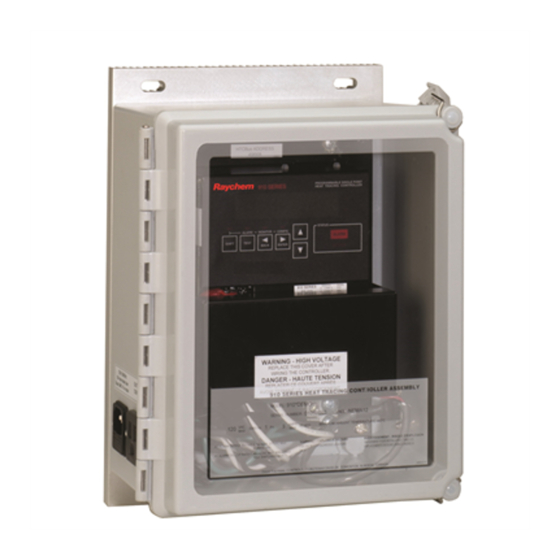
- Page 1 910 Series Heat Trace Controller Installation, Operating and Maintenance Instructions Firmware versions up to V3.1x...
-
Page 2: Table Of Contents
Section 7—Control Modes ........................51 7.1 Introduction ..........................51 7.2 Switch Control Modes ....................... 51 7.3 Load Shedding Control Mode ....................53 Section 8—Troubleshooting ........................54 8.1 Operator Checks ........................54 8.2 Common Problem Areas ......................54 2 | nVent.com... - Page 3 B.2 Optional Stainless Steel EMR Assembly #10170-003 ............63 B.3 Standard Fiberglass SSR Assembly #10170-0002 ..............64 B.4 Optional Stainless Steel SSR Assembly #10170-004 ............. 65 B.5 910 Series HTC Control Module Dimensions ................66 Appendix C—Wiring Diagrams ......................... 67 C.1 TS Wiring ............................ 67 C.2 Power Wiring ..........................
-
Page 4: Certification
Installation and Maintenance Instructions for Firmware Versions up to and Including V3.1X Notice: The information contained in this document is subject to change without notice. CERTIFICATION nVent certifies that this product met its published specifications at the time of shipment from the Factory. LIMITED WARRANTY... -
Page 5: Section 1-Overview
910 product which are listed on the front page. As nVent releases new firmware to modify or enhance the product significantly, new documentation will accompany these releases. To ensure that you are using the correct documentation for your particular version of controller, please check the firmware version number of the 910 against the version number listed on the front of this manual. -
Page 6: Modular Components
CSA C/US The 910 Series of controllers are approved for Class I, Division 2, Groups A, B, C, D hazardous locations making them ideal for direct installation in the field. This may save the significant expense of wiring back to a centrally located electrical distribution center. -
Page 7: Controller Assemblies
Enhanced security is provided by password protection. Single phase current monitoring, ground fault detection, and voltage monitoring are provided. The nVent RAYCHEM 910 Control Module also incorporates a universal power supply, allowing operation directly from 100 to 277 Vac. 1.4.2 COMMUNICATIONS INTERFACE... - Page 8 Option Code Description *232 RS-232 communications option (replace *485 with *232) *MDM Modem communications option (replace *485 with *MDM) *ALR Red LED pilot light Green LED pilot light *ALG Contact your local representative for configurations not listed here. 8 | nVent.com...
-
Page 9: Section 2-Installation And Wiring
If the shipping container is damaged, or the cushioning material shows signs of stress, notify the carrier as well as your nVent representative. -
Page 10: Wiring
Use shielded, twisted, three-conductor wire for the extension of RTD leads. The wire size should ensure that the maximum allowable lead resistance is not exceeded. Shields on RTD wiring should be grounded at the controller end only, using the terminals provided. Temperature Sensors Terminal No. Shield TS 1 Source (WHT) 10 | nVent.com... - Page 11 Ifpresent in a 910 Control Module, the type of communications interface will be identified by a label located on the front of the control module (Figure 2.1). Communications wiring should use nVent RAYCHEM twisted pair, shielded cable. Shields on communications wiring should be grounded at one end only, using the terminals provided.
- Page 12 Neutral/L2 output to trace Wiring diagrams for typical configurations are included in Appendix C. CAUTION: Many wiring configurations will use more than one power source and all must be de-energized prior to performing any maintenance on a controller circuit. 12 | nVent.com...
-
Page 13: Initial Power-Up
Once the cable has been checked, it may be reconnected to the controller and power applied. 2.8.2 RANDOM START DELAY All 910 Series Control Modules incorporate a RANDOM START-UP DELAY feature, ensuring that all units do not power on at the same time. When power is first applied to a controller, it will hold its output off for a random time (0 to 9 seconds), equal to the last digit of the HTCBUS™... -
Page 14: Section 3-Operator Console And Operation
Configure mode • Moves to the previous item in a menu ▵ • Increments the value when editing ▿ • Moves to the next item in a menu • Decrements the value when editing 14 | nVent.com... -
Page 15: Led Indicators
“…” at the end of the message. To enter a sub-menu, press the ▹ key. To move around in the menu, use the ▿ and ▵ keys move to the next and previous items respectively. The ◃ key exits the current menu and returns to the previous menu. nVent.com | 15... - Page 16 3.4.6 PASSCODE PROTECTION The 910 Series Controller provides a passcode for protection of its configuration. You may view any portion of the configuration with the console “locked”; however, when you attempt to initiate an edit session by pressing ▹, you are prompted to enter the passcode. Entering the passcode is just like entering any other numeric value;...
- Page 17 • The console does not have to be unlocked to reset alarms. 3.4.7 FEATURE MODES There are two types Configuration Menus in the 910 Series Controller. 1. A “Basic” Configuration Menu which only contains seven parameters 2. An “Advanced” Configuration Menu which contains all of the parameters Both types of Configuration Menus contain a “Feature Mode”...
-
Page 18: Section 4-Operator Console Modes
HTC RESET = ALARM Time since last reset SWITCH LIMITING = ALARM Load current C.B. LIMITING = ALARM Load current POWER LIMITING = ALARM Power EEROM DATA FAIL = ALARM CONTACTOR COUNT = 200000 Contactor cycle count 18 | nVent.com... -
Page 19: Monitor Mode
TS 2 MAX TEMP 61°C POWER ACCUM 145.9 kW-h CONTACTOR CYCLE COUNT 1234 (only if Deadband or Prop. Amb. Contactor modes are being used) IN USE 2896 h TIME SINCE LAST RESET 675 h ---- END ---- nVent.com | 19... -
Page 20: Configure Mode
---- END ---- This sub-menu is used to set up alarms that relate to any of the temperature sensors. Each alarm may be ENAbled or DISabled, and if the alarm is ENAbled, an alarm setting may be entered. 20 | nVent.com... - Page 21 These include all AC alarms (voltage, current. ground fault, etc.) as well as protection settings such as power limiting, etc. Each alarm may be ENAbled or DISabled. If the alarm is ENAbled, an alarm setting and filter setting may be entered. nVent.com | 21...
- Page 22 {ENA or DIS} (only if Deadband or Prop Amb Contactor are being used) CONTACTOR COUNT {0 to 999999} (only if Deadband or Prop Amb Contactor are being used) EEROM DATA FAIL {ENA or DIS} ---- END ---- 22 | nVent.com...
- Page 23 {ENA or DIS} AUTO-CYCLE {ENA or DIS} AUTO-CYCLE INTERVAL {1 to 240} (only if AUTO-CYCLE=ENA) AUTO-CYCLE UNITS {HOURS or MINUTES} (only if AUTO-CYCLE=ENA) OVERRIDE SOURCE {REMOTE or EXT INPUT} LOAD SHEDDING {ENA or DIS} ---- END ---- nVent.com | 23...
- Page 24 FLASH ALARM OUTPUT {YES or NO} ALARM OUTPUT {N.C. or N.O.} LANGUAGE {ENGLISH or FRANCAIS} PASSCODE {0000 to 9999} (only if 0 or database is unlocked) SCROLL DELAY {0.07 to 0.25} S LOAD DEFAULTS ---- END ---- 24 | nVent.com...
- Page 25 {NONE OR MODEM OR RS-232 or RS-485} DRIVER {AUTO or RS-485 or RS-232 or MODEM} PROFILE {AUTO or 3-WIRE RS-232 or RS-485 or 1200 BAUD MODEM or 300 BAUD MODEM} Tx DELAY {0.00 to 2.50} S ---- END ---- nVent.com | 25...
-
Page 26: Section 5-Configuration Parameter Details
Setting: Any combination of 19 characters from A–Z, 0–9, /, -, ., (, ), or #. Procedure: Using the Operator Console, enter the desired text. 26 | nVent.com... - Page 27 This deadband acts as an on/off control where the decision to turn the output off or on is based upon a window of difference between the measured control temperature and the desired CONTROL SETPOINT temperature. nVent.com | 27...
- Page 28 The HTC switches the output on and off rapidly to limit the average current to an appropriate level. The MAXIMUM POWER level may be adjusted to eliminate stepdown transformers, lower the effective output wattage of a cable, or implement energy management of the heat trace circuit. 28 | nVent.com...
- Page 29 Procedure: Select the type of RTD that is connected to the TS 1 input. IMPORTANT: If a 2 wire 100 Ω Nickel Iron (NI-FE) RTD is selected then the TS 1 LEAD RESISTANCE must be entered manually (see Section 5.2.13). 5.2.13 TS 1 LEAD RESISTANCE (For NI-FE RTDs only.) nVent.com | 29...
- Page 30 TS CONTROL MODE setting or the TS FAIL MODE setting. • If the TS 2 HIGH LIMIT CUTOUT feature is enabled, then the HIGH TS 2 ALARM temperature setting can be set, regardless of whether the HIGH TS 2 ALARM is enabled. 30 | nVent.com...
- Page 31 Procedure: If the override signal will be generated remotely and received by the HTC via the optional communications interface, select REMOTE as the OVERRIDE SOURCE. If the override signal will be received by the HTC via the external input, select EXTERNAL INPUT as the OVERRIDE SOURCE. nVent.com | 31...
- Page 32 The CONSOLE SETPOINT MINIMUM may only be set using a communicating device such as the Model 780/GCC-9000. See the 780/GCC-9000 manual for the proper procedure. IMPORTANT: The CONSOLE SETPOINT MINIMUM is not displayed on the Operator Console. 32 | nVent.com...
-
Page 33: Miscellaneous Setup Parameters
When the output is also configured for normally closed operation, the pilot light will be on steady for normal operation, flash in case of alarm, and be extinguished due to a bulb failure or loss of power. nVent.com | 33... -
Page 34: Temperature Sensor Alarms Configuration
Range: –76°F to 1058°F (–60°C to 570°C) Procedure: Adjust the LOW TS 1 ALARM temperature setpoint to the desired value. Note that the LOW TS 1 ALARM must be enabled in order to adjust the LOW TS 1 ALARM temperature setpoint. 34 | nVent.com... - Page 35 TS 2. 5.4.6 HIGH TEMPERATURE SENSOR 2 ALARM Purpose: If enabled, the HIGH TS 2 ALARM allows for alarming of high temperature conditions as sensed by the second temperature sensor (TS 2). Alarm Mask: ENABLE or DISABLE nVent.com | 35...
- Page 36 If it is important to be aware of any temperature alarm conditions that may have existed in a pipe, then the HTC should be configured for latching temperature alarms. • This setting does not affect the TS FAILURE ALARMS—these are always latching. 36 | nVent.com...
-
Page 37: Other Alarms Configuration
• If the user resets an alarm while the alarm condition is still exists, then the alarm will not be indicated again until the entire alarm filter time has expired. 5.5.3 HIGH LOAD CURRENT ALARM Purpose: Alarms current levels which are higher than a preset limit for the application. nVent.com | 37... - Page 38 Range: 20 to 250 mAmps Procedure: If ground fault tripping is desired, enable the GFI TRIP ALARM and adjust the G.F. TRIP CURRENT to the desired value. To disable ground fault tripping, disable the alarm. Note that the 38 | nVent.com...
- Page 39 • If the user resets an alarm while the alarm condition is still exists, then the alarm will not be indicated again until the entire alarm filter time has expired. nVent.com | 39...
- Page 40 When using parallel-type heaters (zoned constant wattage or self-regulating) or in three-phase installations, the LOW CURRENT ALARM setting must be chosen as close to the lowest expected current as possible to detect failed zones, or cable degradation, 40 | nVent.com...
- Page 41 During a high current condition, the controller attempts to soft start a heating cable using a technique involving measured in-rush current and the SWITCH CURRENT RATING. If the controller is unable to start nVent.com | 41...
- Page 42 The difference in time between when a COMMUNICATIONS FAIL ALARM and an HTC RESET ALARM are logged provide an indication of how long the circuit has been “OFF.” 42 | nVent.com...
- Page 43 Purpose: Generates an alarm if the number of off-to-on transitions of a contactor reaches or exceeds the CONTACTOR COUNT ALARM setting. This serves as a method to perform pre- ventative maintenance on the contactor before a failure is likely to occur. Alarm Mask: ENABLE or DISABLE nVent.com | 43...
-
Page 44: Communications Setup
If you are communicating directly with the controller using a different device, select the MODBUS protocol. For a detailed description of the controller’s MODBUS mapping please refer to 910 Series Heat Trace Controller—Modbus Protocol Interface document. 5.6.2 HTCBUS ADDRESS Purpose: Defines the communications address to be used by the controller when using the HTCBUS™... - Page 45 RS-485 or 1200 BAUD MODEM or 300 BAUD MODEM Procedure: Select the PROFILE to be compatible with other devices that will be connected to the controller for communications purposes. It is recommended that the setting be set to nVent.com | 45...
-
Page 46: Operator Console Functions
LOCK DATABASE feature allows the user to re-lock this modification access once programming has been completed. Procedure: Select the LOCK DATABASE function (at the end of the “Configuration Mode 46 | nVent.com... - Page 47 Purpose: Provides two types of menus on the Operator Console for configuring the 910. Setting: BASIC or ADVANCED Procedure: Select BASIC if access to only the seven most common parameters is required. Select ADVANCED if access to all of the 910 parameters is required. nVent.com | 47...
-
Page 48: Section 6-Monitored Parameter Details
The following text provides a brief summary of each of the measured and calculated parameters that the 910 Series Control Module provides to the user. Detailed information regarding settings, alarms limits, etc. may be found in Section 5 of this manual. -
Page 49: Maintenance Data
The value of this accumulator is written to the controller’s nonvolatile memory once every 24 hours or whenever any maintenance data is reset by the user. nVent.com | 49... - Page 50 This may be useful if the user wishes to use the controller’s external input to monitor the status of an external dry contact and pass this on to another device. Procedure: The EXTERNAL INPUT STATUS may only be viewed using a communicating device. 50 | nVent.com...
-
Page 51: Section 7-Control Modes
Also, when using deadband control, a contactor is not allowed to toggle faster than every two seconds. If an AC alarm with an alarm filter time greater than 0 is detected, the contactor will not toggle until the alarm filter time has expired. nVent.com | 51... - Page 52 Also note that if an AC alarm, with an alarm filter time greater than 0, is detected the contactor will not toggle until the alarm filter time has expired. 52 | nVent.com...
-
Page 53: Load Shedding Control Mode
– both TS 1 and TS 2 have their LOW TS ALARMS enabled • A FORCE ON override signal has higher priority than a load shedding signal. An INHIBIT signal has higher priority than fail safe mode. nVent.com | 53... -
Page 54: Section 8-Troubleshooting
8.1.1 GETTING STARTED In order to access the functions of the 910 Series HTC, use the Operator Console. If the modem communications option is installed in the 910, the Model 780/GCC-9000 Group Communications Controller may also be used to access controller parameters. Refer to the GCC User Manual for operational details. - Page 55 It is not usually a problem to run low signal levels in the same conduit as the power leads even in high power applications, as long as the RTD wire is a twisted, shielded type with an insulation rating equal to or greater than the highest voltage in the conduit. nVent.com | 55...
-
Page 56: Common Alarms-What To Look For
Ground fault alarms can be due to incorrect installation as well as leakage resulting from wet system components or faulted cables. The 910 Series Controller detects ground faults by summing the outgoing and return trace currents through an internal current transformer. Under normal operating conditions (no ground fault condition) this current will be zero. - Page 57 This value sets the upper limit of allowable ground fault leakage. Exceeding this limit will result in the output switch being latched off and the alarm activated to indicate a ground fault condition. Cause of Alarm: • Trip setting too close to normal leakage current nVent.com | 57...
- Page 58 8.3.15 C.B. LIMITING This alarm indicates that the solid state relay is limiting the average current that is applied to the trace circuit to the C.B. CURRENT RATING setting to protect the upstream heater circuit breaker from tripping. 58 | nVent.com...
- Page 59 CONTACTOR COUNT ALARM setting and the contactor should be replaced. Cause of Alarm • Contactor has been controlling the trace circuit for a long time • Some configuration parameter (i.e. DEADBAND, AUTO CYCLE INTERVAL, load shedding etc.) is causing the contactor to toggle more than usual. nVent.com | 59...
-
Page 60: Section 9-Maintenance
SECTION 9—MAINTENANCE 9.1 OPERATOR MAINTENANCE The 910 series controller is designed to be a maintenance-free product. Once installed properly the only maintenance required is retightening of the terminal connections approximately one week after installation and inspection periodically thereafter. Also, alarm pilot lamps (if installed) may need periodic replacement. -
Page 61: Appendix A-Specifications
20 to 250ma, accuracy: ± 2.5% of span ± 2LSD at nominal load, Measurement Range repeatability: ±4% of span Dry Contact 48Vac/dc, 500ma, 10VA switching max. Alarm Relay Output AC Alarm Relay Output 0.75A, 100–277 Vac nom. max. nVent.com | 61... -
Page 62: Appendix B-Typical Enclosure Dimensions
APPENDIX B—TYPICAL ENCLOSURE DIMENSIONS The following drawings provide the user with enclosure size and mounting dimensions for the stock 910 enclosure assemblies. Please contact your local nVent representative for information regarding other available sizes and configurations. B.1 STANDARD FIBERGLASS EMR ASSEMBLY #10170-001... -
Page 63: Optional Stainless Steel Emr Assembly #10170-003
B.2 OPTIONAL STAINLESS STEEL EMR ASSEMBLY #10170-003 nVent.com | 63... -
Page 64: Standard Fiberglass Ssr Assembly #10170-0002
B.3 STANDARD FIBERGLASS SSR ASSEMBLY #10170-0002 64 | nVent.com... -
Page 65: Optional Stainless Steel Ssr Assembly #10170-004
B.4 OPTIONAL STAINLESS STEEL SSR ASSEMBLY #10170-004 nVent.com | 65... -
Page 66: 910 Series Htc Control Module Dimensions
B.5 910 SERIES HTC CONTROL MODULE DIMENSIONS D910 SERIES Mounting slots suitable for a #8 machine screw 66 | nVent.com... -
Page 67: Appendix C-Wiring Diagrams
APPENDIX C—WIRING DIAGRAMS The following drawings provide sample wiring diagrams for the 910 Series control products and optional accessories. Please contact your local nVent representative for information regarding other available options. C.1 TS WIRING Note: Temperature sensor manufacturers may use different lead wire colors than those shown in the diagram above. -
Page 68: Alarm Output Wiring
C.3.1 2-WIRE MODEM OPTION C.3.2 2-WIRE RS-485 OPTION C.3.3 RS-232 OPTION C.4 ALARM OUTPUT WIRING C.4.1 USED AS A DRY CONTACT 68 | nVent.com... - Page 69 C.4.2 USED AS A SWITCHED DC CONTACT C.4.3 USED AS AN AC ALARM RELAY C.4.4 Used as a Powered AC Alarm Relay nVent.com | 69...
-
Page 70: External Input/Output Port Wiring
C.5 EXTERNAL INPUT/OUTPUT PORT WIRING C.5.1 EXTERNAL INHIBIT/OVERRIDE USING A DRY CONTACT C.5.2 EXTERNAL INHIBIT/OVERRIDE USING A DC SIGNAL 70 | nVent.com... -
Page 71: Appendix D-Htc Load Shedding Sequence
APPENDIX D—HTC LOAD SHEDDING SEQUENCE nVent.com | 71... -
Page 72: Appendix E-100 Ω Platinum Rtd Table
1139 142.29 234.91 319.99 1148 144.17 236.65 321.59 1157 146.06 238.39 323.18 1166 147.94 240.13 324.76 1175 149.82 241.86 326.35 1184 151.70 243.59 327.93 1193 153.58 245.31 329.51 1202 155.45 247.04 331.08 1211 157.31 248.76 332.66 1220 72 | nVent.com... -
Page 73: Appendix F-100 Ω Nickel-Iron Rtd Table
295.2 116.5 196.4 297.5 117.9 198.2 299.8 119.2 199.9 301.4 120.6 201.7 303.7 122.0 203.5 306.0 123.4 205.3 308.3 124.8 207.2 310.6 126.2 109.0 312.2 127.6 210.8 314.5 129.0 212.7 316.8 130.5 214.5 319.1 131.9 216.4 320.6 nVent.com | 73... -
Page 74: Appendix G-Factory Default Configuration V3.1X
APPENDIX G—FACTORY DEFAULT CONFIGURATION V3.1X 910 SERIES HTC BASIC MODE MENU (All other parameters are set as shown in the Advanced Mode Sub-Menus) Configuration Mode Menu Parameter Factory User Control Setpoint 68°F (20°C) Lo TS 1 14°F (–10°C) Lo Load 1.0A... - Page 75 *n/a (0 sec) Nominal Resist *n/a (6.00 Ω) Overcurrent Trip *n/a (Enable) Switch Fail Enable HTC Reset Disable C.B. Limiting *n/a (Disable) Power Limiting *n/a (Disable) Switch Limiting *n/a (Disable) Contactor Count Enable Contactor Count 200,000 EEROM Data Fail Enable nVent.com | 75...
- Page 76 *n/a: Parameter may only appear if certain features are enabled. Values shown in brackets are the Factory defaults if the settings are enabled. This information defines the default 910 Series Control Module configuration as set by the Factory for firmware V3.1X. These settings are subject to change without notice.
- Page 77 North America Europe, Middle East, Africa Asia Pacific Latin America Tel +32.16.213.511 Tel +1.800.545.6258 Tel +86.21.2412.1688 Tel +1.713.868.4800 Fax +32.16.213.604 Fax +1.800.527.5703 Fax +86.21.5426.3167 Fax +1.713.868.2333 thermal.info@nvent.com thermal.info@nvent.com cn.thermal.info@nvent.com thermal.info@nvent.com nVent.com ©2018 nVent. All nVent marks and logos are owned or licensed by nVent Services GmbH or its affiliates. All other trademarks are the property of their respective owners. nVent reserves the right to change specifications without notice. Raychem-IM-H56873-910series-EN-1805...
Need help?
Do you have a question about the 910 Series and is the answer not in the manual?
Questions and answers