
Subscribe to Our Youtube Channel
Related Manuals for Pepperl+Fuchs SmartRunner Matcher


Summary of Contents for Pepperl+Fuchs SmartRunner Matcher
- Page 1 FACTORY AUTOMATION MANUAL SmartRunner Matcher* Light section sensor for high- precision profile comparison...
- Page 2 SmartRunner Matcher* With regard to the supply of products, the current issue of the following document is ap- plicable: The General Terms of Delivery for Products and Services of the Electrical Indus- try, published by the Central Association of the Electrical Industry (Zentralverband Elektrotechnik und Elektroindustrie (ZVEI) e.V.) in its most recent version as well as the...
-
Page 3: Table Of Contents
SmartRunner Matcher* Introduction................. 5 Content of this Document ..............5 Target Group, Personnel..............5 Symbols Used ..................5 Product Specifications............... 7 Use and Application................7 Hazards of Laser Radiation..............9 Dimensions..................10 Displays and Controls ............... 10 Interfaces .................... 12 Accessories .................. - Page 4 SmartRunner Matcher* Menu Bar .....................24 5.3.1 File Menu ..................24 5.3.2 View Menu ..................24 5.3.3 Sensor Menu..................25 5.3.4 Image Menu ..................25 5.3.5 Administration Menu ................ 26 5.3.6 Help Menu..................26 Toolbar....................27 Sensor Data..................28 Image Display ..................28 Configuration window ................33 5.7.1...
-
Page 5: Introduction
SmartRunner Matcher* Introduction Introduction Content of this Document This document contains information required to use the product in the relevant phases of the product life cycle. This may include information on the following: Product identification Delivery, transport, and storage ... - Page 6 SmartRunner Matcher* Introduction Warning Messages You will find warning messages, whenever dangers may arise from your actions. It is mandatory that you observe these warning messages for your personal safety and in order to avoid property damage. Depending on the risk level, the warning messages are displayed in descending order as...
-
Page 7: Product Specifications
SmartRunner Matcher* Product Specifications Product Specifications Use and Application This manual applies to the light section sensors VLM350-F280-2E2-1000, VLM350-F280-R4- 1001 and VLM350-F280-R4-1101 (hereafter referred to as sensor). The sensor compares current height profiles with a previously taught-in height profile. The sensor is based on SmartRunner technology and combines the light section method for detecting height profiles with a 2-D vision sensor. - Page 8 SmartRunner Matcher* Product Specifications The integrated control interface of the sensor has been optimized by the factory to report deviations from a previously programed contour. Via the profile comparison, the sensor detects the recorded contour of an object, its correct location, and spacing. In case of a fault, collisions and damage are safely eliminated and lengthy machine downtimes are therefore avoided.
-
Page 9: Hazards Of Laser Radiation
SmartRunner Matcher* Product Specifications Parameterization and Operating Modes The laser-line triangulation sensor can be configured or parameterized via 3 different methods. Reading in code cards via the sensor camera Processing configuration telegrams via the bus interface Using the Vision Configurator software ... -
Page 10: Dimensions
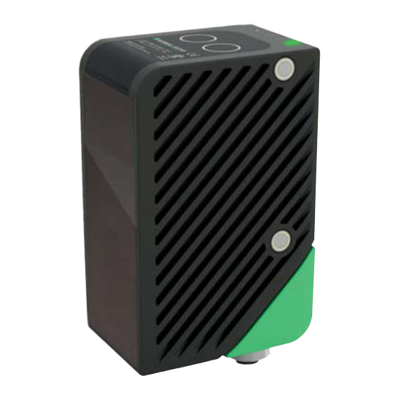
SmartRunner Matcher* Product Specifications Dimensions The devices in the SmartRunner series have the following identical housing dimensions. Figure 2.5 Dimensions of the SmartRunner series Displays and Controls Figure 2.6 Overview of displays and controls... - Page 11 SmartRunner Matcher* Product Specifications Position Designation Function Emitter optic Is used to protect against damage and contamination protective cover Reception optic Is used to protect against damage and contamination protective cover LEDs The functional description for the LEDs can be found in the table below.
-
Page 12: Interfaces
SmartRunner Matcher* Product Specifications Position Designation Function Result (green/red) Lights up green if a scanned profile matches a taught- in profile Lights up red if a scanned profile does not match a taught-in profile Applies in Code Card Lights up green when a correct code has been read ... -
Page 13: Accessories
SmartRunner Matcher* Product Specifications Accessories Order designation Description V19-G-5M-PUR-ABG Single-ended female cordset, M12, 8-pin, shielded, PUR cable VLX-MB1 Mounting aid, adaptable 360° adjustment of mounting head and mounting foot VLX-MB2 Mounting aid, fixing bracket PCV-USB-RS485 Converter USB to RS 485 interface converter... -
Page 14: Installation
2. Check that all items are present and correct based on your order and the shipping documents. If you have any questions, please contact Pepperl+Fuchs. 3. Keep the original packing material in case you need to store or ship the unit at a later time. - Page 15 SmartRunner Matcher* Installation Figure 3.1 Space requirements The surface must be level to prevent the housing from becoming misaligned when the fittings are tightened. We advise securing the screws with spring disks to prevent the sensor becoming misaligned. Following installation of the sensor, ensure that there is still sufficient...
-
Page 16: Electrical Connection
SmartRunner Matcher* Installation Mounting on the underside of the device with M4 screws: You can use the 2 threaded sleeves to mount the housing on the underside of the device. The maximum screw-in depth of the M4 screws is 5 mm. - Page 17 SmartRunner Matcher* Installation Figure 3.3 Connection layout Pepperl+Fuchs single-ended female cordsets are manufactured in accordance with EN60947- 5-2. When using a V19-G-5M-PUR-ABG single-ended female cordset with an open cable end, connector pins are assigned as follows: Wire color Signal Description...
- Page 18 SmartRunner Matcher* Installation Connection using the RS-485 Interface 110 V / 230 V 24 V DC Figure 3.4 PCV-USB-RS-485 Converter Set 1. Plug a plug-in power supply into a socket and connect it to the interface converter. The indicator LEDs on the sensor light up.
-
Page 19: Detection Range
Figure 3.5 Detection range Field of view Note the detection range of the SmartRunner Matcher when planning your plant. You will find more information on the detection range in the following table. Detection range X Distance Z to the sensor... -
Page 20: Commissioning
SmartRunner Matcher* Commissioning Commissioning Connecting the Sensor The sensor is configured using the Vision Configurator software. You have the opportunity to carry out settings on the sensor directly using the Vision Configurator software. Aligning the Sensor Use the image display and diagram display in the Vision Configurator software to optimally align the sensor. -
Page 21: Vision Configurator Software
SmartRunner Matcher* Vision Configurator Software Vision Configurator Software The sensor is commissioned and operated using the Vision Configurator software. The Vision Configurator software makes it easy to operate the sensor with its user-friendly interface. Standard functions include making connections to the sensor, specifying the operating parameters, saving data sets, and displaying data and error diagnostics. - Page 22 SmartRunner Matcher* Vision Configurator Software Figure 5.1 Home screen Wizard - Operation assistant for Vision Configurator The Wizard complements the Vision Configurator configuration software. Double-click on the Wizard button to launch the operation assistant. You will be guided step-by-step through the individual settings.
-
Page 23: Application Window Structure
SmartRunner Matcher* Vision Configurator Software Application Window Structure The application screen opens after you log in. Note! The individual functions depend on the type of sensor connected and the current authorization level, so they are not always all visible. The software is designed to be similar to most Windows applications. -
Page 24: Menu Bar
SmartRunner Matcher* Vision Configurator Software Image display Displays the images captured or stored in the error memory This field can be enabled or disabled via Show images Displays information about the current image and the pixel under the mouse pointer. The following items are... -
Page 25: Sensor Menu
SmartRunner Matcher* Vision Configurator Software Show standard buttons Toggles the display of the buttons in the bar on the left on and off. Show sensor data Hides the display of the sensor data in the top right of the screen. -
Page 26: Administration Menu
SmartRunner Matcher* Vision Configurator Software 5.3.5 Administration Menu Figure 5.7 Administration Menu User administration Opens a window that displays all of the currently created users at the same authorization level or lower. New users with the same authorization level or lower can also be created and deleted here. -
Page 27: Toolbar
SmartRunner Matcher* Vision Configurator Software Toolbar The toolbar can be used to select various functions. Selecting the Connect button establishes a connection between the PC and the sensor. The connection between the PC and the sensor is disconnected. Opens a saved setting. -
Page 28: Sensor Data
SmartRunner Matcher* Vision Configurator Software Sensor Data This section shows the connected device type and firmware version. x.x.x.xxxxx Figure 5.9 Device data Image Display You can evaluate the data recorded in the image display. By analyzing the recorded profile form, it is possible to use the measurement result to make a qualitative assessment. This enables intrusive reflections to be identified and eliminated. - Page 29 SmartRunner Matcher* Vision Configurator Software Designation Function Load image file... Loads a sensor image. You can select the sensor image. Open image folder Opens the storage location Copy image to clipboard Copies image to the clipboard Save image Saves the displayed sensor image Image View - Toolbar The toolbar is located on the left side under the Image View tab.
- Page 30 SmartRunner Matcher* Vision Configurator Software Diagram View You can open the result data graphic under the Diagram View tab. To do this, you must click on the Teach > Trigger laser > Get lines buttons in the toolbar. The graphic can be retrieved using the Get lines button.
- Page 31 SmartRunner Matcher* Vision Configurator Software Diagram View - Toolbar The toolbar is located below the diagram view. There are some useful functions in the toolbar which are used to further process the diagrams. The following functions are available to you.
- Page 32 SmartRunner Matcher* Vision Configurator Software Result View With the SmartRunner, a Quality Good quality threshold can be entered to distinguish between good and bad parts. A good part is taught in to set the quality threshold and the Quality Good value is displayed under the Result View tab. To do this, the Autotrigger must be activated.
-
Page 33: Configuration Window
SmartRunner Matcher* Vision Configurator Software Note! Some of the values under the Result View tab are password-protected. The access permissions are connected by a password level for each user role. The user rights are defined as follows: User/Default: Result, Counter, Quality Good, X Position, Z Position... -
Page 34: Common Tab
SmartRunner Matcher* Vision Configurator Software 5.7.2 Common Tab There are 4 menu items available under the Common tab. The purpose of this section is to present the menu items in detail. Illumination menu item You can adjust the sensor's exposure under the Illumination menu item. - Page 35 SmartRunner Matcher* Vision Configurator Software Mode menu item You can enable or disable "Presentation mode" and "function keys 1 and 2" under the Mode menu item. "Presentation mode" and "function keys 1 and 2" are activated if checked and deactivated if unchecked.
-
Page 36: Matcher Tab
SmartRunner Matcher* Vision Configurator Software 5.7.3 Matcher Tab 4 menu items are available under the Matcher tab. The purpose of this section is to present the menu items in detail. Teach menu item You can adjust the teach-in range of the sensor under the Teach menu item. The teach-in range allows you to restrict the range of the reference height profile. - Page 37 SmartRunner Matcher* Vision Configurator Software Evaluation Menu Item You can adjust the sensor's evaluation range under the Evaluation menu item. The evaluation range is the range in which the sensor seeks out the taught-in height profile. The required "Evaluation ROI" evaluation range is adjusted using the line profile under the "Diagram View"...
- Page 38 SmartRunner Matcher* Vision Configurator Software Match Menu Item You can adjust the x and z tolerance range for the sensor under the Match menu item. The tolerance range determines by how much the height profile may move within the evaluation range and still be recognized.
- Page 39 SmartRunner Matcher* Vision Configurator Software Multiprofile menu item The following description only applies to the "VLM350-F280-R4-1001 and VLM350-F280-R4- 1101". You can save different profiles under the Multiprofile menu item. The stored profiles can be retrieved at any time. You have the option to create up to 32 different profiles. This means you are in a position to respond quickly and flexibly in the case of frequent adjustments to production in particular.
- Page 40 SmartRunner Matcher* Vision Configurator Software Save Parameter Settings The following description only applies to the "VLM350-F280-R4-1001 and VLM350-F280-R4- 1101". The Save job function is used to save parameter data to a read/write tag. This makes it possible to save settings for different profiles on a read/write tag. You have the option to load the saved parameters at any time on your sensor.
-
Page 41: Operation
SmartRunner Matcher* Operation Operation The light section sensor is factory pre-configured to a specific application. As a result, it does not deliver raw data that needs to be evaluated first, but switching signals that are simple to process. The sensor only needs to be mounted, connected, and parameterized using teach-in. - Page 42 Length/bytes Read/write Description 0xA8 GotoParamMode Puts the sensor in Configuration mode 0x01 VendorName Variable String containing "Pepperl+Fuchs" 0x02 VendorHomepage Variable String containing the Pepperl+Fuchs homepage 0x03 ProductName Variable String containing the product name 0x07 SoftwareVersionD Variable String containing the version information...
- Page 43 SmartRunner Matcher* Operation Data Index Parameter name Length/bytes Read/write Description 0xCD Tolerance object Envelope around the taught-in profile in 0.1 mm increments. The envelope is the basis for the quality parameters 0x29 Tolerance X Maximum permissible deviation of the object in the X direction relative to...
- Page 44 SmartRunner Matcher* Operation Note! All values are transferred in little-endian format. In this case, the smallest value byte is stored at the starting address or the smallest value component named first. Read commands always have a length of 0 bytes.
- Page 45 SmartRunner Matcher* Operation [TX] - 84 7B = Result Data [RX] - 00 01 4C 64 64 64 00 00 00 00 29 = Result Data=Good [TX] - D8 27 = Trigger (Object_2) [TX] - 84 7B = Result Data...
- Page 46 SmartRunner Matcher* Operation Description of Quality Parameters Variation Learned curve Current curve Quality Variation = Quality Good = Quality Outliers = Legend Number of values in the taught-in profile curve (x) Distance value of the taught-in profile at position x...
-
Page 47: Code Card Mode
SmartRunner Matcher* Operation Code Card Mode The built-in camera function including LED lighting allows for parameterization using Data Matrix control codes. The control codes are generated using the "Vision Configurator" operating software. All sensor parameters can be specified in a Data Matrix control code. For this purpose, the Data Matrix control code is placed in front of the camera. -
Page 48: Setting Device Parameters Via Control Code
SmartRunner Matcher* Operation 6.2.1 Setting Device Parameters via Control Code Use Vision Configurator to generate control codes. Note! Parameterization mode can be activated only within 10 minutes of the sensor being switched Enabling Code Card Mode Hold down the 2 button on the back of the sensor for more than 2 seconds. Then release the button. -
Page 49: Presentation Mode
SmartRunner Matcher* Operation Presentation Mode You can demonstrate or test the sensor in Presentation mode without the assistance of a PC. Furthermore, the control buttons are activated/deactivated. Setting Presentation Mode 1. Connect the sensor to a power supply. 2. Align the sensor to the measurement object. -
Page 50: Runtime Mode
SmartRunner Matcher* Operation Runtime Mode The Runtime mode is the main mode in which the measuring process operates as configured in the operating software. 6.4.1 Communication via the RS-485 Interface The control panel and reader communicate via the RS-485 interface during operation. Make sure that the basic communication settings have been made on the reader, such as setting the reader address and baud rate. - Page 51 SmartRunner Matcher* Operation 1.Only with VLM350-F280-R4-1001 and VLM350-F280-R4-1101 Response Telegram Status (is alive) The status always returns 0x55 if the sensor is ready for operation. Byte Result Protocol Result Data provides the measurement status and result as a response. Byte...
- Page 52 SmartRunner Matcher* Operation Quality Q00 ... Q26 Quality of the current profile (0 = no profile found, 100 = perfect match) Quality: Quality Good Quality2: Quality Variation Quality3: Quality Outliers Counter Increments for each evaluation, is restarted at 0x3F PosX16 ... PosX00...
- Page 53 SmartRunner Matcher* Operation Software Trigger After sending the sequence for the software trigger, the sensor triggers an image capture. No response telegram is generated to the command. Teach-In After transmitting the command to start the teach-in (0x94), the sensor begins the teach-in routine.
-
Page 54: Maintenance And Repair
SmartRunner Matcher* Maintenance and Repair Maintenance and Repair Maintenance Danger! Risk of death due to electrical current! Contact with live parts causes immediate risk of death. Allow only qualified electricians to carry out work on the electrical installation. Switch off the power supply before carrying out maintenance, cleaning, and repairs, and ... -
Page 55: Troubleshooting
SmartRunner Matcher* Troubleshooting Troubleshooting What to Do in Case of a Fault Before you have the device repaired, take the following actions: Test the plant according to the checklist below. Contact our service center to localize the problem. ... - Page 56 SmartRunner Matcher* Troubleshooting If none of the above remedies the problem, please contact our service center. Please have the fault patterns and the version number of the firmware available. The firmware version number can be found at the top right of the user interface.
-
Page 57: License Note
SmartRunner Matcher* License Note License Note The SmartRunner sensor ships with firmware ("software") programmed into it. This software is based in part on the work of the Independent JPEG Group. The software is based on works by Texas Instruments Incorporated, which are distributed... - Page 58 SmartRunner Matcher* License Note LIMITED TO, PROCUREMENT OF SUBSTITUTE GOODS OR SERVICES; LOSS OF USE, DATA, OR PROFITS; OR BUSINESS INTERRUPTION) HOWEVER CAUSED AND ON ANY THEORY OF LIABILITY, WHETHER IN CONTRACT, STRICT LIABILITY, OR TORT (INCLUDING NEGLIGENCE OR OTHERWISE) ARISING IN ANY WAY OUT OF THE USE OF...
- Page 59 Twinsburg, Ohio 44087 · USA Tel. +1 330 4253555 E-mail: sales@us.pepperl-fuchs.com Asia Pacific Headquarters Pepperl+Fuchs Pte Ltd. Company Registration No. 199003130E Singapore 139942 Tel. +65 67799091 E-mail: sales@sg.pepperl-fuchs.com www.pepperl-fuchs.com Subject to modifications / DOCT-5441C Copyright PEPPERL+FUCHS • Printed in Germany 01/2018...
Need help?
Do you have a question about the SmartRunner Matcher and is the answer not in the manual?
Questions and answers