
Related Manuals for Pepperl+Fuchs SmartRunner Explorer


Summary of Contents for Pepperl+Fuchs SmartRunner Explorer
- Page 1 SmartRunner Explorer Light Section Sensor for High-Precision Profile Capture Manual...
- Page 2 Phone: +49 621 776 - 0 E-mail: info@de.pepperl-fuchs.com North American Headquarters Pepperl+Fuchs Inc. 1600 Enterprise Parkway Twinsburg, Ohio 44087 Phone: +1 330 425-3555 E-mail: sales@us.pepperl-fuchs.com Asia Headquarters Pepperl+Fuchs Pte. Ltd. P+F Building 18 Ayer Rajah Crescent Singapore 139942 Phone: +65 6779-9091 E-mail: sales@sg.pepperl-fuchs.com https://www.pepperl-fuchs.com...
-
Page 3: Table Of Contents
SmartRunner Explorer Contents Introduction........................ 5 Content of this Document ................5 Target Group, Personnel ................5 Symbols Used ....................6 Product Specifications....................7 Use and Application ..................7 Hazards of Laser Radiation ................8 Dimensions..................... 9 Displays and Operating Elements.............. 10 Interfaces and Connections ............... - Page 4 SmartRunner Explorer Contents Vision Configurator Software .................42 Connecting to Vision Configurator.............42 Application Window Structure..............44 Menu Bar.......................46 6.3.1 File Menu .......................... 46 6.3.2 View Menu ........................46 6.3.3 Sensor Menu ........................47 6.3.4 Image Menu ........................47 6.3.5 Administration Menu ......................48 6.3.6...
-
Page 5: Introduction
SmartRunner Explorer Introduction Introduction Content of this Document This document contains information required to use the product in the relevant phases of the product life cycle. This may include information on the following: • Product identification • Delivery, transport, and storage •... -
Page 6: Symbols Used
SmartRunner Explorer Introduction Symbols Used This document contains symbols for the identification of warning messages and of informative messages. Warning Messages You will find warning messages, whenever dangers may arise from your actions. It is mandatory that you observe these warning messages for your personal safety and in order to avoid prop- erty damage. -
Page 7: Product Specifications
Product Specifications Use and Application This manual applies to SmartRunner Explorer light section sensors (hereinafter referred to as "Sensors"). The sensor is based on SmartRunner technology and combines the light section method for detecting height profiles with a 2-D vision sensor. Based on this unique technology, the sensor is able to output both the height profile in global coordinates and 2-D flat images. -
Page 8: Hazards Of Laser Radiation
SmartRunner Explorer Product Specifications Hazards of Laser Radiation This section describes the contents and location of the warning label. The sensor used corresponds to the safety standard IEC 60825-1:2007 for a laser class 1 product. In addition, the US regulation 21 CFR 1040.10 and 1040.11 is fulfilled except for Laser Notice No. -
Page 9: Dimensions
SmartRunner Explorer Product Specifications Dimensions The devices in the SmartRunner series have the following identical housing dimensions. 12.5 Figure 2.3 Dimensions of the SmartRunner series... -
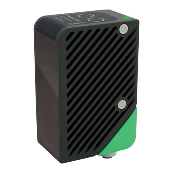
Page 10: Displays And Operating Elements
SmartRunner Explorer Product Specifications Displays and Operating Elements Figure 2.4 Overview of displays and operating elements Posi- tion Designation Function Protective cover for Used to protect against damage and contamination transmitter optics LEDs The functional description for the LEDs can be found in the table below. - Page 11 SmartRunner Explorer Product Specifications Description of the LEDs Ready Power Result LINK RX/TX Figure 2.5 Overview of LEDs Designation Color State Meaning READY Illuminates red if a sensor fault is present (red) and after an update. Flashes red during the update process.
-
Page 12: Interfaces And Connections
SmartRunner Explorer Product Specifications Interfaces and Connections The following connections are located on the sensor. Connection Assignment 24 V DC + IO (voltage supply, inputs, and outputs) M12 plug, A-coded, 8-pin 1. IN trigger 2. + UB 3. nc 4. nc 5. -
Page 13: Network Interface
SmartRunner Explorer Product Specifications Network Interface The network interface transfers the following data. • Control commands (start, stop, operating mode) • Firmware updates (data transfer from the network host to the sensor) • Result data such as scans and images (data transfer from the sensor to the network host) XML-embedded strings are used to transfer parameters and status requests. -
Page 14: Software Interface
NuGet package manager, for example. The DLL can be found in the software folder on the SmartRunner Explorer product page of Pepperl and Fuchs. The NuGet is located in the ZIP file stored in this folder under the project folder ext. -
Page 15: Accessories
SmartRunner Explorer Product Specifications Accessories Various accessories are available. 2.8.1 Voltage Supply Use the following double-ended cordset to connect the voltage supply, inputs, and outputs to the sensor. Field-Attachable Female Connector Model number V19-G-2M-PUR- 8-pin M12 L = 2 m... -
Page 16: Network Cable
SmartRunner Explorer Product Specifications 2.8.2 Network Cable The sensor is connected to the network using an M12 plug. Designation Description V45-G RJ45 network plug, field attachable V1S-G M12 plug, 4-pin, field attachable V1SD-G-2M-PUR-ABG- Cordset, RJ45 network plug with M12 plug, crossed, 4-pin... -
Page 17: Installation
Check the package contents against your order and the shipping documents to ensure that all items are present and correct. Should you have any questions, direct them to Pepperl+Fuchs. Retain the original packaging in case the device is to be stored or shipped again at a later date. -
Page 18: Detection Range
SmartRunner Explorer Installation Detection range Figure 3.1 Detection range Field of view Note the detection range of the SmartRunner Matcher when planning your plant. You will find more information on the detection range in the respective data sheet of the sensor. -
Page 19: Mounting The Sensor
SmartRunner Explorer Installation Mounting the Sensor Note Mounting an optical device • Do not aim the sensor at the sun. • Protect the sensor from direct long-term exposure to sun. • Prevent condensation from forming by not exposing the sensor to any major fluctuations in temperature. - Page 20 SmartRunner Explorer Installation Figure 3.3 Correct orientation The surface must be level to prevent the housing from becoming misaligned when the fittings are tightened. We advise securing the screws with spring disks to prevent the sensor becoming misaligned. Following installation of the sensor, ensure that there is still sufficient space to con-...
-
Page 21: Connecting The Sensor
SmartRunner Explorer Installation Connecting the Sensor Caution! Damage to the device Connecting an alternating current or excessive supply voltage can damage the device or cause the device to malfunction. Electrical connections with reversed polarity can damage the device or cause the device to malfunction. - Page 22 SmartRunner Explorer Installation Establishing a Network Connection To establish a network connection, proceed as follows: Use a network cable that has an RJ45 network connector on one side and a 4-pin M12 plug on the other. Insert the 4-pin M12 plug into the socket on the side of the sensor.
-
Page 23: Setting Up Windows Network Communication Between The Sensor And A Pc/Laptop
SmartRunner Explorer Installation Setting up Windows Network Communication Between the Sensor and a PC/Laptop When the sensor is delivered, it has a fixed IP address: 192.168.2.3. To enable communication within the network, the network settings of your PC/laptop must be synchronized with the sen- sor and may need to be adjusted. - Page 24 SmartRunner Explorer Installation Double-click "Internet Protocol Version 4 (TCP/IPv4)." The Properties window for the TCP/IP protocol opens. Select the "General" tab. Select the input function "Use the following IP address." Enter the IP address of the sensor, but only the first three segments of the IP address. The last segment must be different from the IP address of the sensor.
- Page 25 SmartRunner Explorer Installation Note Changes to the network settings of the PC/laptop require advanced user rights. If necessary, consult with your administrator.
-
Page 26: Commissioning
SmartRunner Explorer Commissioning Commissioning Overview of the commissioning steps: 1. Set the operating distance, see chapter 3.3 2. Mount the sensor, see chapter 3.4 3. Connect the sensor, see chapter 3.5 4. Set up Windows network communication between the sensor and a PC/laptop, see chap- ter 3.6... -
Page 27: Configuration
In order to use the DLL, the NuGet must be integrated. This can be done in Visual Studio by the NuGet package manager, for example. The DLL can be found in the software folder on the SmartRunner Explorer product page of Pepperl+Fuchs. The NuGet is located in the ZIP file stored in this folder under the project folder ext. - Page 28 SmartRunner Explorer Configuration New Driver Instance for TCP/IP Initializes a new driver instance that can be used to communicate with the device via TCP/IP. While the IP address must be specified, the default VSXPORT = 50005 can be used. There is no plugin name for this sensor version. The port and the plugin name are only optional.
- Page 29 SmartRunner Explorer Configuration IVsxMessage An IVsxMessage is a general interface for data exchanged between the PC and the sensor. Asynchronous Function public static (bool Succ, Error ErrorDesc) SaveData(string filename, IVsxMessage message) Possible error IDs: VSX_DRIVER_DATA_ERROR, VSX_DRIVER_INVALID_DATA_ERROR, VSX_DRIVER_SAVE_FILE_ERROR Device Information Returns information about the device (such as MAC address, etc.).
- Page 30 SmartRunner Explorer Configuration Possible error IDs: VSX_DRIVER_CONNECTION_ERROR, VSX_DRIVER_DATA_ERROR Set the Value of a Single Device Parameter Sets the value of a single parameter on the device. The parameter is defined by transferring the function parameters in the same way as for the GetSingleParameterValue function (see description for this function).
- Page 31 SmartRunner Explorer Configuration Change Network Settings Changes the network settings on the device. The connection to the device is disconnected and must be re-established using the "Connect" function. Asynchronous Function public async Task<(bool Succ, Error ErrorDesc)> SetNetworkSet- tings(string ipAddress, string networkMask, string gateway)
- Page 32 SmartRunner Explorer Configuration Reading the Parameter Set Reads the current parameter set from the device and saves it under the specified path and file name. Asynchronous Function public async Task<(bool Succ, Error ErrorDesc)> DownloadParameter- Set(string destinationFileName) Synchronous Function public (bool Succ, Error ErrorDesc) DownloadParameterSet(string des-...
- Page 33 SmartRunner Explorer Configuration Load Factory Settings Loads the factory settings of all parameters on the device. A current parameter list is returned. Asynchronous Function public async Task<(bool Succ, List<Parameter> ParameterList, Error ErrorDesc)> LoadDefaultParameterSetFromDevice() Synchronous Function public (bool Succ, List<Parameter> ParameterList, Error ErrorDesc)
- Page 34 SmartRunner Explorer Configuration Output of the Oldest Buffered DynamicContainer Returns the oldest buffered DynamicContainer (see "DynamicContainer" on page 34) (see ResetDynamicContainerGrabber). timeoutMs specifies the time in ms for which an attempt is made to read a container from the buffer. If no container is present during this time, the function returns an error.
- Page 35 SmartRunner Explorer Configuration Properties Connection Status Indicates the connection status. public bool Connected { get; } Timeout Timeout in ms. This indicates how long to wait for a response to a request sent to the device. The default value is "DEFAULT_ETHERNET_TIMEOUT_MS."...
- Page 36 SmartRunner Explorer Configuration Auxiliary Classes Device Contains information about the currently connected device. public string PhysicalAddress; public int PhysicalPort; public string IpAddress; public string NetworkMask; public string Gateway; public string MacAddress; public string Identifier; public string FirmwareVersion; public string SensorType;...
- Page 37 SmartRunner Explorer Configuration The Following Error IDs Are Possible VSX_DRIVER_NO_ERROR VSX_DRIVER_INIT_ERROR VSX_DRIVER_TIMEOUT_ERROR VSX_DRIVER_SAVE_FILE_ERRO VSX_DRIVER_DATA_ERROR VSX_DRIVER_CONNECTION_ERROR VSX_DRIVER_INVALID_DATA_ERROR VSX_DRIVER_DEVICE_ERROR VSX_DRIVER_GENERAL_ERROR FirmwareState Contains information about the current status of a firmware update that is running. public int Id; public string Tag; public string Message;...
- Page 38 SmartRunner Explorer Configuration DynamicContainer A DynamicContainer received by the sensor can contain the following messages: TagName ?Type? Status Description "Image" ImageData[Mono8] Optional Image data "Line" LineMessage Optional Line data Structure of the LineMessage Type Main Property Line Returns a list of points. Each point consists of image and world coordinates, and quality infor- mation.
- Page 39 SmartRunner Explorer Configuration Width Maximum number of possible line points. Format Reserved for future use. Status Reserved for future use. Lines Returns a list of lines. Usually, the list contains only one line. Each line consists of a list of points, the points of the first line can be called directly via Line.
- Page 40 SmartRunner Explorer Configuration VsxImageData2Message : IVsxMessage Contains image data of a specific image. The individual image values are stored as bytes. public ImageData2Format; public int Width; public int Height; public int LinePitch; public long FrameCounter; public double CoordinateScale; public double CoordinateOffset;...
-
Page 41: Configuration Parameters
SmartRunner Explorer Configuration Configuration Parameters Before the sensor can be used in the system, it must be parameterized. The parameters used for the sensor are listed below. The "read (r)/write (w)" column indicates whether the feature is readable ("r"), writable ("w"), or both ("r/w"). - Page 42 SmartRunner Explorer Configuration Parameter read (r)/ Config ID Parameter ID name Values write (w) Description General 0xCC0001 Custom Name Char[32] r/w User-defined name 0x510001 AutoTrigger Deactivation/activation of cyclical image capture. 0x680001 Exposure time 1 .. 1000 Sets the manual exposure time.
- Page 43 SmartRunner Explorer Configuration Examples of the Application of Configuration Parameters The following declarations are used in these examples: public static class Sr2DParameterIdentifier public static string Name_0x010001 = "0x010001"; public static string Homepage_0x020001 = "0x020001"; public static string Productname_0x030001 = "0x030001";...
- Page 44 Configuration Example Program The example program "ExampleSr2D.cs" is located in the "VSX-Interface libraries..." package. It is intended to make the initial steps of integrating the SmartRunner Explorer easier. The fol- lowing steps are performed in this example program: • TCP/IP connection •...
- Page 45 SmartRunner Explorer Configuration 2. Output of Line Data Wait for the container to be filled. The time for this can be limited to 500 ms, as in this case. This timeout period should be set depending on the data to be received. If there is only one line, about 40 ms is sufficient.
- Page 46 SmartRunner Explorer Configuration 4. Output of Area Image Data Wait for the first container. The time for this can be limited to 500 ms, as in this case. This time- out period can be set depending on the data to be received. A check is then made as to whether the container exists and whether it contains an image.
-
Page 47: Vision Configurator Software
SmartRunner Explorer Vision Configurator Software Vision Configurator Software The sensor is commissioned and operated using the Vision Configurator software. The Vision Configurator software makes it easy to operate the sensor with its user-friendly interface. Standard functions include making connections to the sensor, specifying the operat- ing parameters, saving data sets, and displaying data and error diagnostics. -
Page 48: Connecting To Vision Configurator
SmartRunner Explorer Vision Configurator Software Connecting to Vision Configurator Connecting Sensors Connected sensors can be searched for using the "Auto detect" function (1). To do so, proceed as follows: Ensure that the sensor and the PC/laptop are ready for operation and that there is an Ethernet connection. - Page 49 SmartRunner Explorer Vision Configurator Software Figure 6.2 Home screen Select the sensor "SMARTRUNNER TCP/IP" (2) from the overview window. Click on the "OK" button. The sensor is connected and appears in the application window.
-
Page 50: Application Window Structure
SmartRunner Explorer Vision Configurator Software Application Window Structure The application screen opens after you log in. Note The individual functions depend on the type of sensor connected and the current authorization level, so they are not always all visible. The software is designed to be similar to most Windows applications. - Page 51 SmartRunner Explorer Vision Configurator Software 10 Image display • Displays the images captured or stored in the error memory • This field can be enabled or disabled via Show images 11 Tab Displays information about the current image and the pixel under the mouse pointer.
-
Page 52: Menu Bar
SmartRunner Explorer Vision Configurator Software Menu Bar The menu bar contains a list of menu items. The functionality depends on the type of sensor that is connected and the permissions of the user logged in. Figure 6.3 Menu Bar 6.3.1 File Menu Figure 6.4... -
Page 53: Sensor Menu
SmartRunner Explorer Vision Configurator Software 6.3.3 Sensor Menu Figure 6.6 Sensor menu Load settings Loads the saved settings from the sensor Save settings Saves the settings to the sensor Change network settings Change the network settings. The settings window allows you to... -
Page 54: Image Menu
SmartRunner Explorer Vision Configurator Software 6.3.4 Image Menu Figure 6.7 Image menu Load imagefile Loads the image file Open image folder Opens the folder in which images are currently saved Save image Saves the image currently displayed on the PC... -
Page 55: Help Menu
SmartRunner Explorer Vision Configurator Software 6.3.6 Help Menu Figure 6.9 Help menu Info Displays information about Vision Configurator. Table 6.7 Help menu... -
Page 56: Toolbar
SmartRunner Explorer Vision Configurator Software Toolbar The toolbar can be used to select various functions. Selecting the Connect button establishes a connection between the PC and the sensor. The connection between the PC and the sensor is disconnected. Opens a saved setting. -
Page 57: Device Data
SmartRunner Explorer Vision Configurator Software Device Data The "Device data" area shows the connected device type, firmware version, and MAC ID. x.xx.x.-xxx.xx+xxxx.xxxxxxxx+xxxxx... xx-xx-xx-xx-xx-xx Figure 6.10 Device data Image and Line Display Pictures can be analyzed in the image and line display. By analyzing the recorded profile form, it is possible to use the measurement result to make a qualitative assessment. - Page 58 SmartRunner Explorer Vision Configurator Software Figure 6.12 Result View context menu screen Designation Function Load image file... Loads a sensor image. You can select the sensor image. Open image folder Opens the storage location Copy image to clipboard Copies image to the clipboard...
- Page 59 SmartRunner Explorer Vision Configurator Software Result View - Toolbar Menu The toolbar is located on the left side under the Result View tab. The toolbar contains several useful functions that are used to further process recorded images. The following functions are available.
- Page 60 SmartRunner Explorer Vision Configurator Software Diagram View You can open the result data (height profile) graphic under the Diagram View tab. To do this, click on the Trigger laser buttons in the toolbar. The graphic can be retrieved using the Dia- gram View tab.
- Page 61 SmartRunner Explorer Vision Configurator Software Diagram View - Toolbar The toolbar is located below the diagram view. The toolbar contains several useful functions that are used to further process the diagrams. The following functions are available. Figure 6.18 Diagram View - Toolbar...
-
Page 62: Configuration Window
SmartRunner Explorer Vision Configurator Software Configuration window Various parameters are specified in the configuration window. The individual parameters depend on the current authorization level and are, therefore, not always all visible. Some fea- tures are available in different variants only. Depending on the parameters set, some fields will be grayed out. -
Page 63: Common Tab
SmartRunner Explorer Vision Configurator Software 6.7.2 Common Tab Five menu items are available under the Common tab. The purpose of this section is to pres- ent the menu items in detail. Illumination Menu Item You can adjust the sensor's exposure under the Illumination menu item. - Page 64 SmartRunner Explorer Vision Configurator Software Trigger Menu Item You can enable or disable the autotrigger under the Trigger menu item. Figure 6.22 Trigger menu item Designation Function Autotrigger Checking the box activates a cyclically recurring trigger. The autotrigger must be activated in "Presentation mode".
-
Page 65: Explorer Tab
SmartRunner Explorer Vision Configurator Software 6.7.3 Explorer Tab Two menu items are available under the Matcher tab. The purpose of this section is to present the menu items in detail. Line Menu Item Under the Line menu item, you can adjust the x and z tolerance range for the sensor. The toler- ance range determines by how much the height profile may move within the evaluation range and still be recognized. -
Page 66: Maintenance And Repair
SmartRunner Explorer Maintenance and Repair Maintenance and Repair Servicing Danger! Danger to life due to electrical current! Contact with live parts causes immediate danger to life. • Allow only qualified electricians to carry out work on the electrical installation. •... -
Page 67: Troubleshooting
SmartRunner Explorer Troubleshooting Troubleshooting What to Do in Case of a Fault Before you have the device repaired, perform the following actions: Checklist Fault Cause Remedy "Power" LED The power supply is switched Check whether there is a reason why the... - Page 68 Pepperl+Fuchs Quality Download our latest policy here: www.pepperl-fuchs.com/quality www.pepperl-fuchs.com © Pepperl+Fuchs · Subject to modifications Printed in Germany / DOCT-7301A...
Need help?
Do you have a question about the SmartRunner Explorer and is the answer not in the manual?
Questions and answers