Table of Contents
Advertisement
Advertisement
Table of Contents

Related Manuals for KSB BoosterControl Advanced


Summary of Contents for KSB BoosterControl Advanced
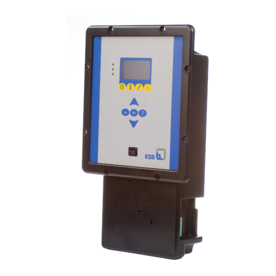
- Page 1 BoosterControl Advanced Installation/Operating Manual...
- Page 2 All rights reserved. The contents provided herein must neither be distributed, copied, reproduced, edited or processed for any other purpose, nor otherwise transmitted, published or made available to a third party without the manufacturer's express written consent. Subject to technical modification without prior notice. © KSB SE & Co. KGaA, Frankenthal 12/03/2018...
-
Page 3: Table Of Contents
Combination options............................ 12 Options................................ 13 Software scope of supply .......................... 13 Dimensions and weight.......................... 13 Installation at Site .......................... 14 Safety regulations............................ 14 Checking ambient conditions ........................ 14 Installing BoosterControl Advanced...................... 14 Electrical connection ............................ 14 5.4.1 Electrical connections ........................ 14 5.4.2 Connection to power supply ...................... 17 5.4.3 Connecting/bridging the motor protection device................ 17 5.4.4... - Page 4 Quick Start Instructions ........................ 32 Commissioning/Start-up/Shutdown.................... 34 Ambient conditions for commissioning and operation ................ 34 Commissioning.............................. 34 8.2.1 Starting up the system........................ 34 Setting BoosterControl Advanced ......................... 34 8.3.1 Setting the display language ...................... 34 8.3.2 Setting the time/date......................... 34 Basic configurations of the pressure booster system ................... 34 8.4.1...
-
Page 5: General
The serial number uniquely describes the product and is used as identification in all further business processes. In the event of damage, immediately contact your nearest KSB service centre to maintain the right to claim under warranty. 1.2 Target group This operating manual is aimed at the target group of trained and qualified specialist technical personnel. -
Page 6: Safety
The product must not be used in potentially explosive atmospheres. BoosterControl Advanced 6 of 88... -
Page 7: Personnel Qualification And Training
▪ Carry out work on the product during standstill only. ▪ As soon as the work has been completed, re-install and/or re-activate any safety- relevant and protective devices. Before returning the product to service, observe all instructions on commissioning. BoosterControl Advanced 7 of 88... -
Page 8: Unauthorised Modes Of Operation
The software has been specially created for this product and thoroughly tested. It is impermissible to make any changes or additions to the software or parts of the software. Software updates supplied by KSB are excluded from this rule. 2.11 Electromagnetic compatibility EMC Directive 2004/108/EC ("Electromagnetic Compatibility") sets out the... -
Page 9: Transport/Temporary Storage/Disposal
1. On transfer of goods, check each packaging unit for damage. 2. In the event of in-transit damage, assess the exact damage, document it and notify KSB or the supplying dealer (as applicable) and the insurer about the damage in writing immediately. -
Page 10: Description
4 Description 4 Description 4.1 General description ▪ Control unit for pressure booster systems With BoosterControl Advanced, up to 3 or 6 pump sets can be started, stopped and controlled as a function of pressure. 4.2 Designation Example: BCA 6 Table 5: Key to the designation... -
Page 11: Technical Data
Communication Communication with field bus systems via the following interfaces: ▪ Profibus ▪ Modbus RTU– RS485 Bus communication with frequency inverters is possible for the following manufacturers: ▪ KSB PumpDrive ▪ Danfoss VLT 2800 ▪ Danfoss Microdrive FC 51 ▪ Danfoss Aquadrive FC 200 4.5 Technical data Table 6: Technical data... -
Page 12: Parameterisable Inputs/Outputs
Not every frequency inverter can be used for every operating mode! Internal bus communication forms the basis for this purpose. The following combinations of frequency inverter and operating mode are recommended by KSB: Table 7: Combinations of frequency inverters and operating modes Cascade operating mode... -
Page 13: Options
Field bus modules ▪ Profibus ▪ Modbus 4.8 Software scope of supply The following software is provided or can be downloaded from the KSB web site at www.ksb.com: ▪ KSB PC software "KSB ServiceTool PactWare for BoosterControl" Also on request: ▪... -
Page 14: Installation At Site
▷ Check the type of current and voltage of the mains. 5.4.1 Electrical connections All electrical connections of BoosterControl Advanced to the power relays or contactors must always have circuit protection. If more than two apparatuses are controlled in a control cabinet, always provide for a separate control voltage supply in the control cabinet (as per EN 60204). - Page 15 Actual-value signal of pressure on discharge side J404 PT dis 24 V Pressure sensor, discharge side PT dis + PT dis - Actual-value signal of pressure on suction side J405 PT inl 24 V Pressure sensor, suction side BoosterControl Advanced 15 of 88...
- Page 16 J301 CAN bus Connections on the expansion board (maximum of 6 pumps) The BoosterControl Advanced version for 6 pumps is equipped with additional terminals in the centre area at the rear of the control system (cannot be retrofitted; factory-set). Terminals P4 - P6 are used to connect the freely parameterisable outputs.
-
Page 17: Connection To Power Supply
Use the following terminals on the printed circuit board: ▪ Terminal strip J403, terminals P1, P2, P3 and COM For more than 3 pumps, also use the following terminals: ▪ Terminal strip J102, terminals P4 - P6 and COM Connect/bridge the thermal circuit breaker. BoosterControl Advanced 17 of 88... -
Page 18: Connecting The Pump Contactors
3. Connect the thermal circuit breaker to BoosterControl Advanced. Motors without thermal circuit breakers: Motors without thermal 1. Bridge the thermal circuit breaker connection on BoosterControl Advanced. circuit breakers Observe terminal wiring diagram. 5.4.4 Connecting the pump contactors The last two terminals can also be used as outputs for signal relays. -
Page 19: Making Optional Connections
▪ Fire alert: terminal strip J403, terminal FIRE with COM The following connections can be made. External signalling devices The external signalling device can be powered via the BoosterControl Advanced control unit if necessary. 1. Bridge the following connections to power the external signalling device: Terminal strip J201, terminal L1, with terminal strip J605A or J605B, left pin 2. - Page 20 - Terminal strip J403, terminals OFF and COM Fire alert In case of a fire alert, BoosterControl Advanced starts all connected pumps at their maximum speed. A fire alert has absolute priority. The system cannot be stopped via the external OFF switch.
-
Page 21: Operation
Table 11: Description of control panel Item Description Function Graphical display Displays information on BoosterControl Advanced operation "Traffic light" LEDs The traffic light function provides information about the pump system's operating status. Menu keys Change to the elements of the first menu level... - Page 22 A start menu can be called from the start screen following the boot procedure. Press "OK" key when on the start screen. The following parameters are displayed: Table 15: Parameters in start menu (depending on operating mode; here, Cascade operating mode) Parameter Value 3-2-1-1 3-5-1 Setpoint 3-5-3 Bandwidth BoosterControl Advanced 22 of 88...
- Page 23 In the "Diagnosis" section, the user is provided with information about faults and warnings that pertain to the pump set or process. This can be done with BoosterControl Advanced in fault (system standstill) or warning (system operational) status. The user can also find previous messages in the history.
- Page 24 Description Possible setting Access Factory setting 3-1-1-1 Display language German Customer English French English Dutch Turkish 6.1.3.3.2 Access levels Four access levels have been defined to prevent accidental or unauthorised access to BoosterControl Advanced parameters: BoosterControl Advanced 24 of 88...
- Page 25 Press the "Settings" menu key. ð 3-1 appears in the top left of the screen. 2. Second digit of parameter number: 3-5-1 Press the arrow key to change the display 3-1 on the screen (upper left) to 3-5. BoosterControl Advanced 25 of 88...
- Page 26 Table 21: Assignment of navigation keys Function Arrow keys: ▪ Move up/down in the menu options. ▪ Increase/decrease a numerical value. Escape key: ▪ Delete/reset entry (the entry is not saved). ▪ Move up one menu level. BoosterControl Advanced 26 of 88...
-
Page 27: Operating The Device Via The Service Interface
CAUTION Improper use of service interface Damage to connected laptop/PC! ▷ Only use the connection cable offered by KSB (USB - RS232). The service interface allows a PC/notebook to be connected via a special cable (USB - RS232). The following actions can be taken: ▪... -
Page 28: General Functions
If you press one of the function keys while editing a parameter, the display will return to the first menu level without saving the parameter. Log in to BoosterControl Advanced. (ð Section 6.6, Page 31) Selecting a parameter (example: 3-5-1) 1. Select menu 3 (3-5-1): 1. -
Page 29: Saving/Loading Factory Settings
1. To load this parameter set, in the selection window, after selecting parameter 3-2-2-6, select the correct target configuration. ð BoosterControl Advanced reboots. 6.4.5 Enabling/disabling the password When the password has been disabled, BoosterControl Advanced always boots at customer access level. ü The user has logged in. 1. Select parameter 3-2-1-2. -
Page 30: Displaying Status Information
Displaying statistics Select parameter 1-3. The following information can be displayed: Parameter description Table 25: Status information 3 Parameter Description 1-3-1 Operating hours of system (hours:minutes) 1-3-2 Time to next service 1-3-3 Actual min. runtime of pump BoosterControl Advanced 30 of 88... -
Page 31: General Information On Parameterisation
The user must log in to the device before settings can be made. 1. Select parameter 3-2-1-1. 2. Enter access level and associated password: - Customer: 7353 Users logged in to BoosterControl Advanced are automatically logged off after 15 minutes of inactivity. BoosterControl Advanced 31 of 88... -
Page 32: Quick Start Instructions
3. Connect/bridge motor protection or fire alert or external ON/OFF. 4. Connect the pump contactors. 5. Connect the pressure sensor/pressure switch. 6. Log in to BoosterControl Advanced at service or factory access level. (ð Section 6.6, Page 31) 7. For cascade operating mode: Set parameter 3-2-2-6 to Hyamat K. - Page 33 3-7-1 Date 3-7-2 Time 3-3-3 For floating frequency inverter operating mode: Hyamat V For frequency inverter per pump operating mode: Hyamat VP BoosterControl Advanced then reboots. 3-3-1 Number of pumps connected BoosterControl Advanced then reboots. BoosterControl Advanced 33 of 88...
-
Page 34: Commissioning/Start-Up/Shutdown
Note the general operating instructions. (ð Section 6, Page 21) 1. Select parameter 3-2-1-1. 2. Enter access level and associated password: - Customer: 7353 Users logged in to BoosterControl Advanced are automatically logged off after 15 minutes of inactivity. 8.3.1 Setting the display language 1. Select parameter 3-1-1-1. -
Page 35: Cascade Control
The jockey pumps are switched off as the larger pumps are cut in. Control with a floating frequency BoosterControl Advanced controls one of the pumps (ð Section 8.4.3, Page 38 inverter via a frequency inverter as a function of pressure. - Page 36 ü The system is operational. ü BoosterControl Advanced has been connected correctly. ü Date and time have been set. (ð Section 8.3.2, Page 34) 1. Log in to BoosterControl Advanced at service or factory access level. (ð Section 6.6, Page 31) 2. Set the parameters for the suction side. (ð Section 8.5.1, Page 45) 3.
-
Page 37: Cascade Control - With Jockey Pump
ü The jockey pump has been sufficiently sized for base-load conditions. ü Date and time have been set. (ð Section 8.3.2, Page 34) 1. Log in to BoosterControl Advanced at service or factory access level. (ð Section 6.6, Page 31) 2. Set the parameters for the suction side. (ð Section 8.5.1, Page 45) 3. -
Page 38: Control With One Frequency Inverter (Per System)
Limit for minimum runtime of pump 0 … 999 s 3-6-4 Maximum pump runtime. After this period, 0 … 356400 s BoosterControl Advanced starts the pump with the least operating hours 3-6-5 When one pump is running: start delay of each 0 … 999 s... - Page 39 Number of pumps in operation × 100 A frequency inverter must be installed in the control cabinet and wired so that it can control any of the pumps. BoosterControl Advanced switches the frequency inverter to another pump after each operation cycle. BoosterControl Advanced...
- Page 40 Limit for minimum runtime of pump 0 ... 999 s 3-6-4 Maximum pump runtime. After this period, 0 ... 356400 s BoosterControl Advanced starts the pump with the least operating hours 3-6-5 When one pump is running: start delay of each 0 ... 999 s...
-
Page 41: Control With One Frequency Inverter Per Pump (Sequential Starting/Stopping Of Pumps)
ü The system is operational. ü BoosterControl Advanced has been connected correctly. ü Date and time have been set. (ð Section 8.3.2, Page 34) 1. Log in to BoosterControl Advanced at service or factory access level. (ð Section 6.6, Page 31) 2. Set the parameters for the suction side. (ð Section 8.5.1, Page 45) 3. -
Page 42: Control With One Frequency Inverter Per Pump (Synchronous Operation Of Pumps), Multiple Pump Operation
Maximum setpoint 0 ... x kPa 3-6-4 Maximum pump runtime. After this period, 0 ... 356400 s BoosterControl Advanced starts the pump with the least operating hours 3-6-5 When one pump is running: start delay of each 0 ... 999 s... - Page 43 ü The system is operational. ü BoosterControl Advanced has been connected correctly. ü Date and time have been set. (ð Section 8.3.2, Page 34) 1. Log in to BoosterControl Advanced at service or factory access level. (ð Section 6.6, Page 31) 2. Set the parameters for the suction side. (ð Section 8.5.1, Page 45) 3.
-
Page 44: Setting The Frequency Inverter Parameters
8.4.6 Setting the frequency inverter parameters Parameter settings can only be made at the service or factory access level. Log in to BoosterControl Advanced at service or factory access level. (ð Section 6.6, Page 31) The menu at parameter 3-4-3 only appears if an operating mode with frequency inverter has been selected at parameter 3-3-3. -
Page 45: Application Functions
Nominal frequency of frequency inverters 0 ... 50 Hz 8.5 Application functions BoosterControl Advanced has many useful features that are described in this section: 8.5.1 Setting the parameters for dry running protection Table 35: Parameter settings for dry running protection Parameter... -
Page 46: Parameterisation Of Inlet Tank Function
0 ... 60 min activated/deactivated 8.5.3 Parameterisation of inlet tank function BoosterControl Advanced can open and close an inlet tank proportional valve as a function of the filling level in the inlet tank. Several possibilities for level detection are available: ▪... - Page 47 Proportional valve 8.5.3.1 Level control via proportional valve If a proportional valve is used. Valve has been connected. (ð Section 5.4.7, Page 18) Log in to BoosterControl Advanced at service or factory access level. (ð Section 6.6, Page 31) Set the following parameters Table 38: Level control via proportional valve...
- Page 48 January - December 0 ... 31 8.5.3.3 Level detection via pressure sensor ü Pressure sensor has been connected. 1. Log in to BoosterControl Advanced at service or factory access level. (ð Section 6.6, Page 31) Set the following parameters: Table 41: Level detection via pressure sensor...
-
Page 49: Parameterising The Accumulator Function (Frequency-Controlled Systems Only)
▪ Proportional valve (ð Section 8.5.3.1, Page 47) 8.5.3.6 Level control via motorised gate valve If a motorised gate valve is used. Log in to BoosterControl Advanced at service or factory access level. (ð Section 6.6, Page 31) Set the following parameters: Table 44: Level control via motorised gate valve... - Page 50 1. To activate the water flow detector, select parameter 3-3-4 and configure it as follows, depending on the set-up of the system: Log in to BoosterControl Advanced at the service or factory access level. (ð Section 6.6, Page 31) Table 46: Activating the water flow detector...
-
Page 51: Fire-Fighting Function
Pulse length of water flow detector 2 4 s detector 3-6-12 Pulse length of water flow detector 3 4 s KSB recommends the following pulse length values for a water flow detector: Table 48: Pulse lengths for water flow detector Accumulator size Pulse length 0 ... -
Page 52: Automatic Setpoint Reduction In Case Of Inlet Pressure Drop (Asr)
A corresponding warning is output. If the inlet pressure drops below the switch-off point specified in 3-4-1-5-4, the system stops. Log in to BoosterControl Advanced at service or factory access level. (ð Section 6.6, Page 31) Table 50: Automatic setpoint reduction (dynamic inlet pressure monitoring) -
Page 53: Setting Freely Parameterisable Inputs
8.5.12 Setting freely configurable outputs BoosterControl Advanced offers the option of outputting remote signals. To this end, hardware outputs P4 to P6 (J 104) of a BoosterControl Advanced for 6 pumps must be connected to the remote control signalling device accordingly. The control system settings must then be made in accordance with the parameter list using the service tool. -
Page 54: Configuration Example
▪ When the system pressure has increased to more than 1.4 bar, the fault can be acknowledged manually. The system then starts again. 8.5.14 Setting alternative setpoint using a timer Log in to BoosterControl Advanced at service or factory access level. (ð Section 6.6, Page 31) Table 56: Parameter settings for alternative setpoint... -
Page 55: Servicing/Inspection
▷ Prevent BoosterControl Advanced from being re-started unintentionally when carrying out any maintenance and installation work. NOTE All maintenance, service and installation work can be carried out by KSB Service or authorised workshops. Find your contact in the attached "Addresses" booklet or on the Internet at "www.ksb.com/contact". -
Page 56: Parameter List
10 Parameter list Table 57: Overview of parameters Parameter Description Factory setting Possible settings min. value max. value Read access right Write access right Operation Everybody Nobody Display of operating mode System Everybody Nobody General operating status indicators System pressure 1-1-1 Everybody Nobody Displaying the measured system pressure... - Page 57 Parameter Description Factory setting Possible settings min. value max. value Read access right Write access right WSD pulses tank 3 1-1-16 Everybody Nobody Water flow detection, number of fills in tank 3 Pumps Everybody Nobody Pump-relevant status information Operating mode 1-2-1 Everybody Everybody Setting the operating mode for each...
- Page 58 Parameter Description Factory setting Possible settings min. value max. value Read access right Write access right Clear History 2-1-4 Service Service Deleting the message history Settings Everybody Nobody Settings Everybody Nobody Control panel Basic settings Everybody Nobody 3-1-1 Basic settings for control panel Language 3-1-1-1 English...
- Page 59 Parameter Description Factory setting Possible settings min. value max. value Read access right Write access right Logo 3-1-4-1 No logo KSB logo, Service Service Selecting of logo displayed dp logo, no logo Device Everybody Nobody Device-specific settings Login 3-2-1 Everybody...
- Page 60 Parameter Description Factory setting Possible settings min. value max. value Read access right Write access right Edit Pump Opera. hrs 3-2-2-7 Service Service Editing pump operating hours Pump number 3-2-2-7.1.1 1.. 6 Service Service Number of pump Hours 3-2-2-7.2.1 0.. 500000 500000 Service Service...
- Page 61 Parameter Description Factory setting Possible settings min. value max. value Read access right Write access right Leakage detection 3-3-5 Everybody Service Activating leakage monitoring MPO Functionality 3-3-6 Off, Service Service Synchronous operation PumpMode int/ext 3-3-7 Internal Internal, Everybody Service Setting for pump mode via HMI (internal) external or switch (external) System settings...
- Page 62 Parameter Description Factory setting Possible settings min. value max. value Read access right Write access right Threshold 3-4-1-4-8 Everybody Service 1 or 2 extra signalling relay contacts for switching thresholds Threshold 1 ON 3-4-1-4-8-1 0...199 Everybody Service Inlet tank level for relay 1 energised in percent Threshold 1 OFF 3-4-1-4-8-2...
- Page 63 Parameter Description Factory setting Possible settings min. value max. value Read access right Write access right Analog output 3-4-1-4-10-5 4-20mA 4-20 mA, Everybody Service Configuring the analog output 0-20 mA Auto. Setpoint Redu. 3-4-1-5 Everybody Nobody Automatic setpoint reduction in case of inlet pressure drop ASR function 3-4-1-5-1...
- Page 64 Parameter Description Factory setting Possible settings min. value max. value Read access right Write access right Variable freq. drive 3-4-3 Everybody Nobody Configuring the frequency inverters Communication 3-4-3-1 None None, Everybody Service Configuring the communication protocol for Analog 4-20 mA, Analog 0-20 mA, the frequency inverter PumpDrive,...
- Page 65 Parameter Description Factory setting Possible settings min. value max. value Read access right Write access right Jog frequency 3-4-3-23 30.. 50 Everybody Service Speed in manual mode Jog ramp time 3-4-3-24 0,04.. 3600 0,04 3600 Everybody Service Ramp time Costing select 3-4-3-25 Digital and bus Digital input,...
- Page 66 Parameter Description Factory setting Possible settings min. value max. value Read access right Write access right Rated Freq 3-4-5-2 45.. 50 Everybody Service Rated frequency of pump Switch On Freq. 3-4-5-3 31.. 50 Everybody Service Start frequency of pump Switch Off Freq. 3-4-5-4 30..
- Page 67 Parameter Description Factory setting Possible settings min. value max. value Read access right Write access right Set point 3-5-1 0.. 1000 1000 Everybody Customer Entering the pressure setpoint (system pressure) Bandwidth 3-5-3 0.. 999 Everybody Customer Bandwidth within which the frequency inverters remain at the same, constant speed independent of pressure.
- Page 68 Parameter Description Factory setting Possible settings min. value max. value Read access right Write access right Opt. pump starts /h 3-6-1 0.. 99 Everybody Service Entering the optimal pump starts per hour. The pump runtime is automatically adapted Min. run time 0..
- Page 69 Parameter Description Factory setting Possible settings min. value max. value Read access right Write access right Month 3-7-1.1.2 1.. 12 Everybody Customer Setting the month 3-7-1.1.3 1.. 31 Everybody Customer Setting the day of the week Time 3-7-2 Everybody Customer Setting the time Time 0..
- Page 70 Parameter Description Factory setting Possible settings min. value max. value Read access right Write access right Date adapt level On 3-7-9 Everybody Customer The alternative fill level is activated in accordance with day(s)/month(s). Month adapt level On 3-7-9.1.1 Off, Everybody Customer January, Entering the month in which the alternative...
- Page 71 Parameter Description Factory setting Possible settings min. value max. value Read access right Write access right Adaptation mode 3-7-8-1 Off, Everybody Customer Configuring the alternative setpoint to take Weekly, effect on a daily or weekly basis Daily Change on/off times 3-7-8-2 Everybody Customer...
- Page 72 Parameter Description Factory setting Possible settings min. value max. value Read access right Write access right Input 1 3-8-1-1 None None, Service Service Configuration of input 1 forced start (check run), alt. setpoint, leakage, remote acknowledgement, bypass valve, emergency power Input 2 3-8-1-2 None...
- Page 73 Parameter Description Factory setting Possible settings min. value max. value Read access right Write access right Output 4 (FR4) 3-8-2-4 None None, Service Service Configuration of output 4 threshold 1, threshold 2, supply valve, bypass valve, lack of water Output 5 (FR5)Output 5 (FR5) None None, Service...
- Page 74 Parameter Description Factory setting Possible settings min. value max. value Read access right Write access right direct off 3-11-2 Off, Service Service Energy-saving mode is carried out without zero-flow detection function Power down speed % 3-11-3 1.. 99 Service Service Calculated stop speed if zero-flow detection is activated in energy-saving mode (in %).
- Page 75 Parameter Description Factory setting Possible settings min. value max. value Read access right Write access right Valve Function 3-14-1 Off, Everybody Service Activating/deactivating the valve forced start (check function run), PT 1000, digital input Open delay 0.. 20 Everybody Service 3-14-2 Delay time that lapses before valve is opened.
- Page 76 Parameter Description Factory setting Possible settings min. value max. value Read access right Write access right IO Info Everybody Nobody IO Info IO information for internal communications unit IO Serial Number Everybody Nobody 4-2-1 IO Serial Number IO information for serial number of internal communications unit IO FW-Version 4-2-2...
- Page 77 Parameter Description Factory setting Possible settings min. value max. value Read access right Write access right PB HW-Revision 4-4-3 Everybody Nobody PB HW Revision Information for hardware of Profibus Modbus Info Everybody Everybody Modbus Info Information for Modbus used MB FW-Version 4-5-1 Everybody Nobody...
-
Page 78: Trouble-Shooting
Internal 24 V voltage outside permissible range ✘ 5V out of range Internal 5 V voltage outside permissible range ✘ 3V out of range Internal 3 V voltage outside permissible range ✘ External off External command for system stop active ✘ BoosterControl Advanced 78 of 88... - Page 79 Over voltage P5 DC link voltage too high, frequency inverter 5 ✘ Over voltage P6 DC link voltage too high, frequency inverter 6 ✘ Under voltage P1 DC link voltage too low, frequency inverter 1 ✘ BoosterControl Advanced 79 of 88...
- Page 80 Setpoint reduced due to drop in inlet pressure ✘ Factory Test No test carried out in factory ✘ MPO Failure Fault in VP mode, synchronous operation ✘ ASR Shutdown Cancellation of automatic setpoint reduction ✘ BoosterControl Advanced 80 of 88...
-
Page 81: Related Documents
□ Check the start and stop levels. □ Check messages for correct function and effect. □ Determine the spare parts requirements, if any. □ Train operating personnel. □ Provide new operating manual if necessary. □ BoosterControl Advanced 81 of 88... -
Page 82: Eu Declaration Of Conformity
13 EU Declaration of Conformity 13 EU Declaration of Conformity KSB SE & Co. KGaA Manufacturer: Johann-Klein-Straße 9 67227 Frankenthal (Germany) The manufacturer herewith declares that the product: BoosterControl Advanced ▪ is in conformity with the provisions of the following Directives as amended from time to time: –... -
Page 83: Index
Power supply 17 Pressure sensor 18, 48 Proportional valve 47 Functional check run 52 Functions Communication 11 Control system 10 Quick-start instructions 33 Monitoring 11 Safety 6 Graphical display 21 Safety awareness 7 Scope of supply Software 13 Service interface 27 Help key 27 Specialist personnel 7 Start menu 22 Storage 9 BoosterControl Advanced 83 of 88... - Page 84 Index Technical data 11 Traffic light 21 Training 7 Transport 9 Warnings 23 Graphical control panel 21 Warranty claims 5 Weight 13 BoosterControl Advanced 84 of 88...
- Page 88 KSB SE & Co. KGaA Johann-Klein-Straße 9 • 67227 Frankenthal (Germany) Tel. +49 6233 86-0 www.ksb.com...
Need help?
Do you have a question about the BoosterControl Advanced and is the answer not in the manual?
Questions and answers